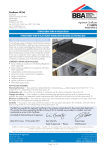
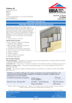
1
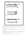
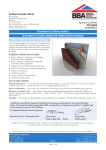
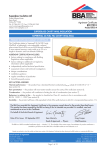
APPROVAL
INSPECTION
TESTING
CERTIFICATION
Celotex Limited
Lady Lane Industrial Estate
Hadleigh
Ipswich
Suffolk IP7 6BA
Tel: 01473 822093 Fax: 01473 820880
TECHNICAL APPROVALS FOR CONSTRUCTION
Agrément Certificate
09/4667
e-mail: [email protected]
website: www.celotex.co.uk
Product Sheet 1
CELOTEX INSULATION
CELOTEX RANGE OF PIR INSULATION BOARDS FOR TIMBER-FRAME DWELLINGS
PRODUCT SCOPE AND SUMMARY OF CERTIFICATE
This Certificate relates to the Celotex Range of PIR
Insulation Boards for Timber-Frame Dwellings, a range
of rigid polyisocyanurate (PIR) foam boards with
aluminium foil facings for use between studding, as an
insulated lining, an insulated sheathing or as part of a
system incorporating any combination of these options
in walls of conventional timber-frame dwellings.
AGRÉMENT CERTIFICATION INCLUDES:
• factors relating to compliance with Building
Regulations where applicable
• factors relating to additional non-regulatory
information where applicable
• independently verified technical specification
• assessment criteria and technical investigations
• design considerations
• installation guidance
• regular surveillance of production
• formal three-yearly review.
KEY FACTORS ASSESSED
Thermal performance — typical wall constructions incorporating the products can achieve U values between
0.11 W·m–2·K–1 and 0.29 W·m–2·K–1. The thermal conductivity (90/90 value) of the products is declared by the
Certificate holder as 0.022 W·m–1·K–1 (see section 5).
Risk of condensation — the products can contribute to minimising the risk of surface condensation (see section 6).
Behaviour in relation to fire — walls incorporating the products have been tested to BS 476-21 : 1987 (see section 7).
Durability — the products are durable and sufficiently stable to remain effective as an insulation for the life of the
building (see section 13).
The BBA has awarded this Agrément Certificate to the company named above for the products described
herein. These products have been assessed by the BBA as being fit for their intended use provided they are
installed, used and maintained as set out in this Certificate.
On behalf of the British Board of Agrément
Date of Second issue: 12 October 2010
Chris Hunt
Greg Cooper
Originally certificated on 6 September 2009
Head of Approvals — Physics
Chief Executive
Certificate amended on 3 November 2010 with updated information in the Thermal performance section.
The BBA is a UKAS accredited certification body — Number 113. The schedule of the current scope of accreditation for product certification is
available in pdf format via the UKAS link on the BBA website at www.bbacerts.co.uk
Readers are advised to check the validity and latest issue number of this Agrément Certificate by either referring to the BBA website or contacting the BBA direct.
British Board of Agrément
Bucknalls Lane
Garston, Watford
Herts WD25 9BA
©2010
Page 1 of 12
tel: 01923 665300
fax: 01923 665301
e-mail: [email protected]
website: www.bbacerts.co.uk
Regulations
In the opinion of the BBA, the Celotex Range of PIR Insulation Boards for Timber-Frame Dwellings, if used in
accordance with the provisions of this Certificate, will meet or contribute to meeting the relevant requirements of the
following Building Regulations:
The Building Regulations 2010 (England and Wales)
Requirement: B2
Internal fire spread (linings)
Comment:
Requirement: B3(1)(4)
Internal fire spread (structure)
Walls incorporating the products can meet this Requirement. See section 7.2 of this Certificate.
Comment:
Walls incorporating the products must comply with this Requirement. See sections 7.1 and 7.3 of this
Certificate.
Requirement: C2(a)(b)(c)
Resistance to moisture
Comment:
Requirement: L1(a)(i)
Conservation of fuel and power
Comment:
Requirement: Regulation 7
Materials and workmanship
Comment:
The products are acceptable. See section 13 and the Installation part of this Certificate.
Walls incorporating the products can meet this Requirement. See sections 6.1 and 6.3 of this Certificate.
The products are acceptable. See sections 5.3 to 5.5 of this Certificate.
The Building (Scotland) Regulations 2004 (as amended)
Regulation:
8(1)
Regulation:
Standard:
9
2.4
2.5
2.6
3.15
6.1(b)
6.2
Carbon dioxide emissions
Building insulation envelope
The products are acceptable, with reference to clauses, or parts of, 6.1.2(1), 6.1.3(2), 6.1.6(1), 6.2.1(1),
6.2.3(1), 6.2.4(2), 6.2.6(2), 6.2.7(1)(2), 6.2.12(1)(2) and 6.2.13(1)(2) of these Standards. See sections 5.3 to
5.5 of this Certificate.
Comment:
Regulation:
Condensation
The products can contribute to satisfying this Standard, with reference to clauses 3.15.1(1), 3.15.4(1) and
3.15.5(1). See sections 6.2 and 6.3 of this Certificate.
Comment:
Standard:
Standard:
Spread to neighbouring buildings
Walls incorporating the products can satisfy this Standard, with reference to clause 2.6.1(1). See sections
7.1 and 7.3 of this Certificate.
Comment:
Standard:
Internal linings
Walls incorporating the products will satisfy this Standard, with reference to clause 2.5.1(1)(2). See section
7.2 of this Certificate.
Comment:
Standard:
Building standards — construction
Cavities
Walls incorporating the products must comply with this Standard, with reference to clauses 2.4.1(1)(2) and
2.4.2(1)(2), 2.4.7(1) and 2.4.9(2). See section 7.3 of this Certificate.
Comment:
Standard:
Fitness and durability of materials and workmanship
The products satisfy the requirements of this Regulation. See section 13 and the Installation part of this
Certificate.
Comment:
12
Building standards — conversions
All comments given for the products under Regulation 9 also apply to this Regulation, with reference to
clause 0.12(1)(2) and Schedule 6(1)(2)
Comment:
(1) Technical Handbook (Domestic).
(2) Technical Handbook (Non-Domestic).
The Building Regulations (Northern Ireland) 2000 (as amended)
Regulation:
B2
Fitness of materials and workmanship
Comment:
Regulation:
C5
Condensation
Comment:
Regulation:
E3(a)
Internal fire spread — Linings
Comment:
Regulation:
E4(1)(4)
Internal fire spread — Structure
Comment:
Regulation:
F2(a)(i)
Conservation measures
Comment:
Regulation:
F3(2)
Target carbon dioxide Emission Rate
Comment:
The products are acceptable. See section 13 and the Installation part of this Certificate.
Walls incorporating the products can satisfy this Regulation. See section 6.3 of this Certificate.
Walls incorporating the products can meet this Regulation. See section 7.2 of this Certificate.
Walls incorporating the products can satisfy this Regulation. See sections 7.1 and 7.3 of this Certificate.
The products are acceptable. See sections 5.3 to 5.5 of this Certificate.
The products can contribute to a building satisfying its target emission rate. See sections 5.3 to 5.5 of
this Certificate.
Page 2 of 12
Construction (Design and Management) Regulations 2007
Construction (Design and Management) Regulations (Northern Ireland) 2007
In the opinion of the BBA, there is no information in this Certificate which relates to the obligations of the client,
CDM co-ordinator, designer and contractors under these Regulations.
Non-regulatory Information
NHBC Standards 2010
NHBC accepts the use of the Celotex Range of PIR Insulation Boards for Timber-Frame Dwellings, when installed and
used in accordance with this Certificate, in relation to NHBC Standards, Chapter 6.2 External timber framed walls.
General
This Certificate relates to the Celotex Range of PIR Insulation Boards for Timber-Frame Dwellings, rigid polyisocyanurate
(PIR) foam, faced on both sides with low emissivity aluminium foil facings. The products can be used between studding,
as an insulated lining, an insulated sheathing or as part of a system incorporating any combination of these options in
walls of conventional timber-frame dwellings.
Technical Specification
1 Description
1.1 The Celotex Range of PIR Insulation Boards for Timber-Frame Dwellings comprises Celotex TB4000, GA4000,
XR4000 and FR4000 PIR insulation boards consisting of PIR foam, faced on both sides with low emissivity aluminium
foil facings.
1.2 The boards can be fixed between the studding, as an insulated dry lining and as insulated sheathing facing
the cavity.
1.3 The boards are available with the nominal properties shown in Table 1.
Table 1 Nominal properties
Product
PIR core
composition
Thickness
Dimensions
Core
density
(kg·m–3)
Edge
detail
Water vapour
resistance (MN·s·g–1)
(mm)
Compressive
strength
(kPa)
(mm)
TB4000(1)
Unreinforced
12–45
1200 x 2400
>120
26–29
Plain
>150
GA4000
Reinforced (except
50 mm and 100 mm
= unreinforced)
50–100
1200 x 2400
>120
26–30
Plain
>150
Unreinforced
110–200
1200 x 2400
>120
29–32
Plain
>150
Reinforced
25–90 mm and
unreinforced 100 mm
and above
25–150
1200 x 2400
>120
32
Plain
>150
XR4000
FR4000(2)
(1) Used as lining only.
(2) Thickness 25–45 mm used as lining only.
2 Delivery and site handling
2.1 The boards are delivered in wrapped packs. Each pack contains a label with the manufacturer’s name and the
BBA identification mark incorporating the number of this Certificate.
2.2 The boards must be protected from prolonged exposure to sunlight and should be stored either under cover or
protected with opaque polythene sheeting. Where possible, packs should be stored inside. If stored outside, the
boards should be stacked flat and raised above ground level, and not in contact with ground moisture.
2.3 Care must be exercised in handling individual boards to avoid crushing the edges or corners.
2.4 Boards must not be exposed to open flame or other ignition sources.
Assessment and Technical Investigations
The following is a summary of the assessment and technical investigations carried out on the Celotex Range of
PIR Insulation Boards for Timber-Frame Dwellings.
Page 3 of 12
Design Considerations
3 General
3.1 The Celotex Range of PIR Insulation Boards for Timber-Frame Dwellings is effective in reducing the thermal
transmittance (U value) of external walls of timber-frame dwellings. It is essential that such walls are designed and
constructed to incorporate the normal precautions against moisture ingress, including a breather membrane over the
timber sheathing.
3.2 New buildings subject to the national Building Regulations should be designed in accordance with the relevant
recommendations of BS EN 1995-1-1 : 2004.
3.3 Constructions incorporating a masonry outer leaf (includes masonry units and natural stone blocks) should be in
accordance with BS EN 1996-2 : 2006. The designed residual cavity width should be 50 mm and at no point less
than 35 mm wide(1).
(1) A residual cavity nominally 50 mm wide will be required by the NHBC where normal standards of tolerance and workmanship are adopted.
3.4 It is recommended that services which penetrate the dry lining, eg light switches, power outlets, are kept to a
minimum to limit damage to vapour checks. In addition, any penetrations should be either enclosed in plasterboard or
stone mineral wool or suitably tested proprietary fire-rated systems to preserve the fire resistance of the wall.
3.5 This application requires the specifying of a vapour control layer (VCL) behind the internal finish. The VCL should
take the form of 500 gauge polythene or plasterboard backed with a vapour control membrane (or similar).
3.6 Installation must not be carried out until the moisture content of the timber frame is less than 20%.
3.7 When used as insulated sheathing, the products will not contribute to the structural performance of the timber frame.
4 Practicability of installation
The products are designed to be installed by a competent general builder, or a contractor, experienced with these
types of products.
5 Thermal performance
5.1 Calculations of thermal transmittance (U value) should be carried out in accordance with BS EN ISO 6946 :
2007, BRE Report (BR 443 : 2006) Conventions for U-value calculations and 0.022 W·m–1·K–1 declared thermal
conductivity (90/90 value) of the insulation, and an emissivity value of 0.05 for the foil facer.
5.2 The U value of a completed wall will depend on the selected insulation thickness and the insulating value of the
masonry and the internal finishes. Calculated U values for example constructions are given in Tables 2(a) to 2(e).
Table 2(a) Example wall U values (1)
— inter studs (system 1)
Insulation thickness
(mm)
Table 2(c) Example wall U
values (1) — sheathing (system 3)
Table 2(b) Example wall U values (1)
— inter studs and dry-lining (system 2)
Inter stud
(W·m–2·K–1)
Insulation thickness
(mm)
75(2)
0.25
12+75(2)
0.20
50(2)
0.29
100(2)
0.21
12+100(2)
0.16
75(2)
0.22
(2)
120
0.19
12+120
0.17
150(3)
0.15
30+75(2)
0.18
165(3)
0.15
30+100(2)
0.15
200
0.13
30+120
0.15
(3)
(2)
(2)
Table 2(d) Example wall U values (1)
— inter studs and sheathing (system 4)
Insulation thickness
(mm)
Inter stud and dry-lining
(W·m–2·K–1)
(1)
Insulation thickness
(mm)
100
(2)
Insulation thickness
(mm)
Lining and
sheathing
(W·m–2·K–1)
70+50(2)
0.15
12+50(2)
0.24
100+50(2)
0.13
12+75(2)
0.19
(2)
120+50
0.12
12+100
0.16
75+75(2)
0.13
30+50(2)
0.20
100+75
0.11
30+75
(2)
0.16
120+75
0.11
30+100
0.14
(2)
0.17
Table 2(e) Example wall U values (1)
— lining and sheathing (system 5)
Inter stud
and sheathing
(W·m–2·K–1)
(2)
Sheathing
(W·m–2·K–1)
(2)
(2)
(1) Typical timber-frame construction comprising 102 mm brick leaf, 50 mm unventilated cavity, 9 mm OSB board, 15% timber studs, 12.5 mm plasterboard.
(2) 140 mm width timber studs.
(3) 200 mm width timber studs.
Page 4 of 12
5.3 When considering insulation requirements, designers should refer to the detailed guidance contained in the
documents supporting the national Building Regulations. The U values shown in Tables 2(a) to 2(e) indicate that
the products can enable, or contribute to enabling, a wall to achieve typical design U values referred to in those
supporting documents (see Tables 3, 4 and 5).
Table 3 Mean design wall U values — England and Wales (1)
Construction
U value (W·m–2·K–1)
Notional non-domestic building
0.26
Existing building — new and replaced wall
0.28
Dwelling new-build limit
0.30
Existing building — renovated or retained walls
0.30
Notional dwelling
0.35
Non-domestic new-build limit
0.35
(1) Flexible approaches on existing buildings are given in the Approved Documents.
Table 4 Mean design wall U values — Scotland (1)
Construction
U value (W·m–2·K–1)
Notional dwelling
0.19
New dwelling simplified method
0.19
Conversion unheated building (into dwellings)
0.19
Extension to dwelling
0.19
Alterations and reconstructions to a dwelling
0.22
Stand-alone building <50 m to a dwelling
0.22
New non-dwelling limit for shell and fit out
0.23
2
New dwelling limit
0.25
Conversion of unheated building
0.25
Non-domestic extension, alteration and reconstructions
0.25
New non-domestic limit
0.27
Conversion of heated building
0.30
Notional non-dwelling
0.30
(1) Flexible approaches on existing buildings are given in the Technical Handbooks.
Table 5 Mean design wall U values — Northern Ireland (1)
Construction
U value (W·m–2·K–1)
Existing building; new wall
0.30
Notional dwelling
0.35
Notional non-domestic building
0.35
Building new-build limit
0.35
Existing building — replaced, renovated and retained wall
0.35
(1) Flexible approaches on existing buildings are given in the Technical Booklets.
New buildings
5.4 Walls with U values lower than (or the same as, for dwellings in Scotland) the relevant ‘notional’ value specified
in Tables 3, 4 or 5 will contribute to a building meeting its Target Emission Rate. Walls with higher U values will
require additional energy saving measures in the building envelope and/or services.
5.5 The products can maintain, or contribute to maintaining, continuity of thermal insulation at junctions between
elements. For Accedited Construction Details, the corresponding psi values in BRE Information Paper IP1/06 Assessing
the effects of thermal bridging at junctions and around openings, Table 3 may be used in carbon emission calculations
in Scotland and Northern Ireland. Detailed guidance for other junctions and on limiting heat loss and air infiltration can
be found in:
England and Wales — Approved Documents to Part L and for new thermal elements to existing buildings, Accredited
Construction Details (version 1.0). See also SAP 2009 Appendix K and the iSBEM User Manual for new-build.
Scotland — Accredited Construction Details (Scotland)
Northern Ireland — Accredited Construction Details (version 1.0).
5.6 For existing buildings, such as extensions or conversions, walls will be acceptable where they do not exceed the
relevant U value in Tables 3, 4 or 5 and junctions and openings comply with section 5.5.
Page 5 of 12
6 Risk of condensation
Surface condensation
6.1 Walls will limit the risk of surface condensation adequately when the thermal transmittance (U value) does
not exceed 0.7 W·m–2·K–1 at any point, and the junctions with other elements are designed in accordance with
section 5.5.
6.2 Walls will adequately limit the risk of surface condensation when the thermal transmittance (U value) does
not exceed 1.2 W·m–2·K–1 at any point. Guidance may be obtained from BS 5250 : 2002, Section 8, and
BRE Report (BR 262 : 2002) Thermal insulation: avoiding risks.
Interstitial condensation
6.3 Walls incorporating the products will adequately limit the risk of interstitial condensation when they are
designed and constructed in accordance with BS 5250 : 2002 (Section 8 and Annex D).
6.4 Both foil facings have a water vapour resistance exceeding 70 MN·s·g–1 and the insulation core has a water
vapour resistivity of 300 MN·s·g–1m–1 and can provide a significant resistance to water vapour transmission when all
joints between boards are taped for over stud applications.
6.5 When used as insulated sheathing, the joints between the boards must not be taped. If the products are to be
used in the external walls of rooms expected to have high humidity, care must be taken to provide adequate permanent
ventilation to avoid possible problems from the formation of interstitial condensation in the wall.
7 Behaviour in relation to fire
7.1 A fire-resistance test was carried out in accordance with BS 476-21 : 1987 on a loadbearing, timber stud
wall system. An assessment considered the likely fire resistance of all systems (see Table 6) as if they had been
tested to BS 476-21 : 1987. The main points of the assessment highlighted that:
• all systems are suitable for applications where a fire resistance of up to 30 minutes is required against the
loadbearing capacity, integrity and insulation criteria of BS 476-21 : 1987 (for fire exposure from the inside, when
subject to a total imposed load of 60 kN (10 kN load per stud)(1)
• for loads greater than this, a qualified structural engineer can utilise the BS 476-21 : 1987 fire-resistance test report
and the accompanying assessment, to alter the design of the timber frame to ensure that the residual timber after
30 minutes will be adequate. The Certificate holder should be contacted for these reports
• openings for doors and windows should be framed out and any exposed timber covered with at least one layer of
plasterboard (see also section 3.4).
(1) Relates only to walls with a masonry outer leaf. Other weather-resistant claddings should be demonstrated by an appropriate test or assessment.
Table 6
System construction details
Component
Description
System
1
2
3
4
5
Inter stud Inter stud Sheathing Inter stud
Lining
and lining
and sheathing and sheathing
Plasterboard
12.5 mm, ( = 0.25 W·m–1·K–1)
yes
yes
yes
yes
yes
Batten
25 mm x 50 mm
–
yes
–
–
–
Celotex
Minimum 12 mm
–
yes
–
–
yes
500 gauge polythene (or plasterboard backed
with a vapour control membrane — 0.15 mm)
yes
yes
yes
yes
yes
140 mm by 38 mm timber studs at maximum 600 mm centres,
with cross noggings at 1200 mm centres, staggered by
600 mm between bays ( = 0.13 W·m–1·K–1 — 15% default fraction)
yes
yes
yes
yes
yes
Minimum 60 mm between studs
yes
yes
–
yes
–
9 mm OSB or plywood ( = 0.13 W·m ·K )
yes
yes
yes
yes
yes
Minimum 50 mm
–
–
yes
yes
yes
yes
yes
yes
yes
yes
50 mm
yes
yes
yes
yes
yes
102.5 mm ( = 0.77 W·m–1·K–1)
yes
yes
yes
yes
yes
Vapour control layer
Timber frame
Celotex
Structural sheathing
Celotex
–1
–1
Breather membrane
Cavity
Brick
General notes about fixings:
• plasterboard: Systems 1, 2 and 3 — 50 mm by 3.5 mm drywall screws at nominal 150 mm centres.
• plasterboard: System 2 — 110 mm by 4.1 mm drywall screws at nominal 150 mm centres to a fixing depth of 40 mm.
• OSB: System 1 — 25 mm by 3.5 mm cross-head screws at nominal 600 mm centres.
• OSB: Systems 2 and 3 — 50 mm by 3.5 mm cross-head screws at nominal 600 centres.
• Celotex PIR insulation: System 3 — clips on wall ties (minimum of three ties per square metre).
• timber battens: System 2 — 4.1 mm cross-head screws at nominal 300 mm centres to a fixing depth of 40 mm into the studs.
• wall ties: timber-frame ties should be used in line with fixing manufacturer’s instructions. Typical values: 17 W·m–1·K–1, cross-section 18 mm2 and 3.7 fixings per m2.
Page 6 of 12
7.2 The products, TB4000 and GA4000 (up to 90 mm) have a Class 1 rating surface spread of flame when tested
to BS 476-7 : 1997. FR4000 achieves Class 0 in accordance with BS 476 Parts 6 and 7.
7.3 Cavity barriers must be provided to comply with:
England and Wales — Approved Document B, Section 6
Scotland — Mandatory Standard 2.4, clauses 2.4.1(1)(2), 2.4.2(1)(2), 2.4.7(1) and 2.4.9(2).
(1) Technical Handbook (Domestic).
(2) Technical Handbook (Non-Domestic).
Northern Ireland — Technical Booklet E, paragraphs 3.35 to 3.38.
8 Proximity of flues and appliances
When installing the products in close proximity to certain flue pipes and/or heat-producing appliances, the following
provisions to the national Building Regulations are acceptable:
England and Wales — Approved Document J
Scotland — Mandatory Standard 3.19, clauses 3.19.1(1)(2) to 3.19.9(1)(2).
(1) Technical Handbook (Domestic).
(2) Technical Handbook (Non-Domestic).
Northern Ireland — Technical Booklet L
9 Weathertightness
9.1 Constructions incorporating the products and built in accordance with section 3.3 will resist the transfer of
precipitation to the inner leaf and satisfy the national Building Regulations:
England and Wales — Requirement C2(a)(b)(c)
Scotland — Mandatory Standard 3.10, clause 3.10.5(1)(2)
(1) Technical Handbook (Domestic).
(2) Technical Handbook (Non-Domestic).
Northern Ireland — Regulation C4.
9.2 In all situations it is particularly important to ensure during installation that:
• wall ties and fixings are installed correctly and are thoroughly clean
• excess mortar is cleaned from the cavity face of the brick leaf and any debris removed from the cavity
• installation is carried out to the highest level on each wall or the top edge of the insulation is protected by a cavity tray
• at lintel level, a cavity tray, stop ends and weepholes, must be provided.
10 De-rating of electrical cables
As with other insulation products, it may be necessary in some cases to de-rate electrical cables buried in insulation. In
BS 7671 : 2008 it is suggested that where wiring is completely surrounded by insulation, it may need to be de-rated
to as low as half its free air current carrying capacity. Guidance should be sought from a qualified electrician.
11 Infestation
Use of the products does not in itself promote infestation. The creation of voids within the structure, ie gaps between the
wall lining and the boards may provide habitation for insects or vermin in areas already infested. Care should be taken
to ensure, wherever possible, that all voids are sealed, as any infestation may be difficult to eradicate. There is no food
value in the materials used.
12 Maintenance
As the insulation component of the products are confined behind the wall lining and they have suitable durability (see
section 13), maintenance is not required.
13 Durability
The boards are rot proof, stable and durable and will have a life equivalent to that of the wall structure in which
they are incorporated.
Installation
14 General
14.1 Installation of the Celotex Range of PIR Insulation Boards for Timber-Frame Dwellings must be in accordance with
the relevant clauses of BS EN 1996-1-1 : 2005 and the Certificate holder’s instructions. Installation details of the three
constructions are given in Figure 1.
14.2 The boards are light to handle, and cut easily but care must be taken to prevent damage, particularly at edges.
14.3 Damaged boards should not be used; small areas of damaged faces may be repaired with self-adhesive
aluminium foil tape.
Page 7 of 12
Figure 1 Installation details
vapour control layer
25 mm x 25 mm batten
plasterboard
stud
Celotex GA4000/XR4000/FR4000
9 mm OSB sheathing
breather membrane
inter stud only
25 mm x 50 mm batten
Celotex TB4000 or FR4000
Celotex GA4000/XR4000/FR4000
breather membrane
inter stud and lining
vapour control layer
9 mm OSB sheathing
Celotex GA4000/XR4000/FR4000
sheathing only
Inter studs
14.4 The products should be cut to fit tightly between the timber studding and positioned against the inner face of
sheathing board. Any gaps should be filled with expanding insulation foam. The insulation should be held in place by
nails or timber battens to the warm side of the insulation.
14.5 The void created by space between the inner surface of the products and the dry lining can be utilised as an
insulated service duct.
14.6 A sealed polythene vapour control layer with a minimum thickness of 0.125 mm (500 gauge) with lapped and
sealed joints is placed over the stud face before applying the internal finish.
Inter studs and lining
14.7 A sealed polythene vapour control layer with a minimum thickness of 0.125 mm (500 gauge) with lapped and
sealed joints is placed over the stud face. To satisfy the requirements of NHBC Standards 2010, a vapour control
layer should be placed on the warm side of the wall insulation.
14.8 The boards are temporarily fixed to the inner face of the timber studding ensuring that the insulation makes
contact or over laps with ceiling and floor insulation.
14.9 The line of the timber studs is marked on the boards to allow fixing of plasterboard.
Page 8 of 12
14.10 Boards should be butted tightly against each other to prevent gaps. Taping the joints with aluminium foil/
reinforced tape, provides an effective vapour control layer and an air permeability barrier. To achieve an adequate
bond, the boards should be thoroughly clean and free from any contamination.
14.11 The insulation is sealed at all service penetrations.
14.12 The plasterboard is fixed over the board on battens and secured with conventional nails or screws to the
appropriate length, and finished as normal.
Sheathing
14.13 The boards should be installed on the outside of any wood, OSB or board sheathing closely butted with joints
staggered and should be restrained using galvanized clout nails at 300 mm centres around the board perimeters and
at 400 mm centres for intermediate timbers within the board area.
14.14 It is essential that nails locate the studs and this can be achieved by either using a plumb line from the top of
the studs or by marking the stud positions on the boards (or substrate timber sheathing) as the boards are being offered
into position.
14.15 The use of self-adhesive foil tape is not recommended.
14.16 A sealed vapour control layer with lapped and sealed joints is placed between the plasterboard and the
timber frame.
14.17 Ties securing the external leaf are fixed through the board to the studs and the sheathing is held in place by the
retaining discs on the wall ties.
14.18 Internal finishes are applied as normal.
Technical Investigations
15 Investigations
An examination was made of test data relating to:
• water vapour resistance
• density
• thermal conductivity
• compressive strength
• dimensional accuracy
• dimensional stability with temperature and humidity
• condensation risk.
Page 9 of 12
Bibliography
BS 476-7 : 1997 Fire tests on building materials and structures — Method of test to determine the classification of the
surface spread of flame of products
BS 476-21 : 1987 Fire tests on building materials and structures — Methods for determination of the fire resistance of
loadbearing elements of construction
BS 5250 : 2002 Code of practice for control of condensation in buildings
BS EN 1995-1-1 : 2004 Eurocode 5 : Design of timber structures — General — Common rules and rules for buildings
BS EN 1996-1-1 : 2005 Eurocode 6 : Design of masonry structures — General rules for reinforced and unreinforced
masonry structures
BS EN 1996-2 : 2006 Eurocode 6 : Design of masonry structures — Design considerations, selection of materials and
execution of masonry
BS 7671 : 2008 Requirements for electrical installations. IEE Wiring Regulations. Seventeenth Edition
BS EN ISO 6946 : 2007 Building components and building elements — Thermal resistance and thermal transmittance
— Calculation method
Page 10 of 12
Conditions of Certification
16 Conditions
16.1 This Certificate:
• relates only to the product/system that is named and described on the front page
• is granted only to the company, firm or person named on the front page — no other company, firm or person may
hold or claim any entitlement to this Certificate
• is valid only within the UK
• has to be read, considered and used as a whole document — it may be misleading and will be incomplete to be
selective
• is copyright of the BBA
• is subject to English law.
16.2 Publications and documents referred to in this Certificate are those that the BBA deems to be relevant at the date
of issue or re-issue of this Certificate and include any: Act of Parliament; Statutory Instrument; Directive; Regulation;
British, European or International Standard; Code of Practice; manufacturers’ instructions; or any other publication or
document similar or related to the aforementioned.
16.3 This Certificate will remain valid for an unlimited period provided that the product/system and the manufacture
and/or fabrication including all related and relevant processes thereof:
• are maintained at or above the levels which have been assessed and found to be satisfactory by the BBA
• continue to be checked as and when deemed appropriate by the BBA under arrangements that it will determine
• are reviewed by the BBA as and when it considers appropriate.
16.4 In granting this Certificate, the BBA is not responsible for:
• the presence or absence of any patent, intellectual property or similar rights subsisting in the product/system or any
other product/system
• the right of the Certificate holder to manufacture, supply, install, maintain or market the product/system
• individual installations of the product/system, including the nature, design, methods and workmanship of or related
to the installation
• the actual works in which the product/system is installed, used and maintained, including the nature, design,
methods and workmanship of such works.
16.5 Any information relating to the manufacture, supply, installation, use and maintenance of this product/system
which is contained or referred to in this Certificate is the minimum required to be met when the product/system is
manufactured, supplied, installed, used and maintained. It does not purport in any way to restate the requirements
of the Health & Safety at Work etc Act 1974, or of any other statutory, common law or other duty which may exist
at the date of this Certificate; nor is conformity with such information to be taken as satisfying the requirements of the
1974 Act or of any statutory, common law or other duty of care. In granting this Certificate, the BBA does not accept
responsibility to any person or body for any loss or damage, including personal injury, arising as a direct or indirect
result of the manufacture, supply, installation, use and maintenance of this product/system.
Page 11 of 12
British Board of Agrément
Bucknalls Lane
Garston, Watford
Herts WD25 9BA
©2010
Page 12 of 12
tel: 01923 665300
fax: 01923 665301
e-mail: [email protected]
website: www.bbacerts.co.uk