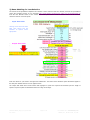
1
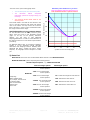
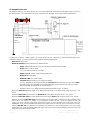
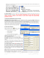
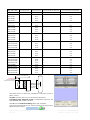
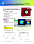
Beam Profiling … Engineered as a system
… Delivered as a Solution
DataRay Inc. User Guide
WinCamD + M2DU M2 system
Applies to: Software
Ver. 6.00S6St or higher, running under Windows XP with SP2 or higher or Windows Vista.
Very Important: With full Administrator Rights, Install, Open and Close the latest Software before
connecting the Camera or the Stage. Windows Vista? See link at website.
Short of time?
Save yourself time by carefully following this User Guide the first time. Done properly once, the
next time will be simple and fast.
Once done, for future convenience, so you need only look at page 1, copy your lens setup details from page 7.
Lens focal length
LD (User measured)
+(A–Zo Delta)
See diagram pages 8
See diagram page 8
= LPPSO
(Enter in M2 dialog)
Lens Principal Plane to Sensor at 0
Zo Delta (Enter in M2 dialog)
Front of lens mount to Principal Plane
Applications
−
M2 measurement of CW & pulsed lasers
−
M2 measurement of focused beams
−
Focus position of laser assemblies
Features
−
ASR™ Auto Scan Range for ISO compliant scan
−
USB 2.0 for field service applications
−
Fast, Compact, Portable system
L x W x H: 8 x 2.9 x 4.3” (200 x 109 x 74 mm)
Total weight 4 lb, (1.8 kg)
−
Field-replaceable lens options
Contents
Page
1) Description
2
2) Beam Modeling for Lens Selection
3
3) Parts List
4
4) Getting Started
5
5) Assemble the unit
6
6) Laser Safety
7
7) Preset the Attenuation level correctly
7
8) Start the Software
7
9) Align the Beam
9
10) Set the Capture Block
9
11) Check Exposure
& optionally subtract residual noise
9
12) Perform a Coarse Scan
11
13) Perform a Final Scan
11
14) Source Beam Characteristics
12
15) Save the data
12
16) Second time around
13
17) Support
18) Manual M2
13
(with a different translation Stage)
14
Known M2DU bugs in Version 6.00S2d? Inclusion region on small complex beams may lose track.
Saved files sometimes open incorrectly. Expected correction mid-Feb ’08.
[Future updates are downloadable from http://www.dataray.com/files/iDataRayUpdate.exe]:
WinCamD-M2DU_Stage_User_Guide.docx
Rev. 0901c
Page 1 of 15
For contacts visit: www.dataray.com
DataRay Inc., Boulder Creek, CA, USA
1) Description
The
USB 2.0 M2DU accessory converts WinCamD beam
profiling cameras into a compact fully ISO 11146 compliant,
M2 measurement system.
The M2DU system comprises a lens fixed to the front of a
42.5 mm travel stage on which the WinCamD is carried.
An achromat refocuses an input beam to a waist within the
stage travel range. The standard is 100 mm focal length.
Alternative lens focal lengths and coatings will be
recommended/supplied for some lasers. A spreadsheet
simplifies the choice.
ASR™ auto-sampling measures the hyperbolic region about
the waist and at zR>2 in accordance with the ISO standard.
A least squares hyperbolic fit to the second moment
diameter data allows calculation of the M2 value and related
parameters for both the focused beam and the source beam.
M2 Beam Quality Factor - Explained
M2, or Beam Quality Factor, is a dimensionless parameter that characterizes the degree of imperfection of a real-world
laser beam. The closer the M2 value is to 1.0, - i.e. the closer the beam is to TEM00 Gaussian perfection - the closer the
beam can be focused to its diffraction limited spot size.
Due to limitations of the optical cavity, the lasing medium, and/or the output/ancillary optics, most beams are not the
‘perfect’, diffraction-limited, Gaussian profile, pure TEM00 mode described in textbooks. Complex beams can contain
multiple TEMxy contributions leading to high values of M2.
At its simplest M2 may defined as: The ratio of the divergence of the actual beam, to that of a theoretical, diffractionΘ
limited TEM00 beam with the same waist diameter.
2
M =
Θ = The measured, far-field, full-angle divergence of the actual beam
θ
θ = The theoretical far-field divergence of a ‘perfect’ TEM00 Gaussian beam which has the same waist
2λ
θ=
diameter as the measured beam.
πW0
Where: 2W0 = The second moment (4σ) beam waist diameter.
The shape of the M2 curve may be shown to be hyperbolic of the form:
2W ( z ) = 2W 0
Where zR is the Rayleigh Range, defined as the distance at which the beam diameter is √2
greater than the diameter at the waist. zR may be shown to be:
⎛ π ⎞
M2 = ⎜
⎟.Θ.2W0
⎝ 4λ ⎠
A definition of M2 in terms of a measured diameter is:
Specifications
Max. beam diams.: See graph right.
−
400 to 800 nm with standard lens
−
260 to 1150 nm with optional lenses
−
To 1350 nm on high power beams with
optional lenses
−
M2 Range* 1 to >50
−
M2 Accuracy* ± 5% typical
−
M2 Repeatability* ± 2% typical
* Beam dependent. Achieving absolute accuracy
better than ±5 % is possible, but can be difficult.
2W 0 π.W02
= 2
Θ
M .λ
25
100 mm standard lens
150 mm lens option
20
250 mm lens option
500 mm lens option
15
10
5
0
200
400
600
800
1000
1200
1400
1600
Wavelength λ nm
WinCamD-M2DU_Stage_User_Guide.docx
Rev. 0901c
2
Max. Input beam φ at max. Mag (@ s = F) at profiler res. limit.
Max. Input Beam Diam. in mm
−
zR =
⎛ z ⎞
1+ ⎜ ⎟
⎜ ⎟
⎝ zR ⎠
Page 2 of 15
For contacts visit: www.dataray.com
DataRay Inc., Boulder Creek, CA, USA
1800
2) Beam Modeling for Lens Selection
An intuitive Excel spreadsheet simplifies lens selection. Some customers will have already received this spreadsheet
during the purchase process. If not, download http://www.dataray.com/files/Lens_choice_for_M2_measurement.xls
from the User Manuals section at the website and model your beam in order to ensure that it can be correctly
measured with the received system.
−
Input data fields
Clicking on the Excel cell offers
both input advice and the
selection of options where
appropriate.
−
Output data fields
Enter the values for your beam in the light-blue shaded cells. The results of the Gaussian optics calculations appear in
the dark pink shaded cells and a curve appears below.
The output data fields show several factors and highlights in yellow the required lens diameter plus the length of
spacers required to place the beamwaist within the range of the stage.
WinCamD-M2DU_Stage_User_Guide.docx
Rev. 0901c
Page 3 of 15
For contacts visit: www.dataray.com
DataRay Inc., Boulder Creek, CA, USA
The lines on the (auto-scaled) graph show:
The estimated post-lens beamwaist profile.
•
The
calculated
flattest
acceptable
beamwaist (maximum Rayleigh Range) for
this stage.
•
The minimum allowed beam waist for the
chosen profiler.
If the beam waist is too small for the camera or the
curve is too flat, warnings with advice will appear
next to the values. You may need to be in the far
field of the laser in order to form a beamwaist within
the range of travel of the stage.
Avoid destruction of your camera sensor!
For the calculated value of 2Wo”, boxed in green
above, from the curves in the WinCamD manual
(page 1-7 for CW, 1-8 for pulsed), determine
whether
you
will
need
to
add
additional
sampling/attenuation in order to avoid saturation of
the camera at the focus. If so add as required before
proceeding.
350
300
250
Beam Diameter in μm
•
Beamwaist profile AFTER lens for your beam
Beam must NOT be flatter than (below) this line
Lower beamwaist limit due to profiler resolution
An additional ND2.0 filter is provided as standard.
Chapter 5 of the WinCamD manual describes
attenuation and sampling solutions. DataRay offers
additional ND filters, variable ND filters, wedge
samplers, & holographic beam samplers to assist
you.
200
150
100
50
0
0
10
20
30
40
z position in mm in the moving stage
3) Parts List
WinCamD-U series head. The recommended default camera is the WinCamD-UCD12.
M2DU-WC-XXX-XXX system comprising the following options:
Standard System Options
e.g. M2DU-WC-250-NIR
Lens focal length options
-75
M2DU-WC
Comprising:
USB 2.0 M2DU Stage
2.5 μm steps, 44 mm travel
3 m flexible cable
Lens mount bracket
Mounted lens
Power brick
Wavelength options
100 mm focal length
22 mm aperture
-100 100 mm focal length
22 mm aperture
-150 150 mm focal length
22 mm aperture
-UV
Fused silica singlet for 250-450 nm
-VIS Achromat for 400-800 nm
-150-50 150 mm focal length
47 mm aperture
-250 250 mm focal length
22 mm aperture
-NIR Achromat for 630-1100 nm
-TEL Achromat for 1000-1800 nm
-250-50 250 mm focal length
47 mm aperture
-500-50 500 mm focal length
47 mm aperture
WinCamD-M2DU_Stage_User_Guide.docx
Rev. 0901c
Page 4 of 15
For contacts visit: www.dataray.com
DataRay Inc., Boulder Creek, CA, USA
50
4) Getting Started
Short of time? Save yourself time by carefully following through this User Manual the first time that you use the
equipment. Once you have done it properly once, the next time will be simple and fast.
This User Guide assumes that the WinCamD system is installed, has been run with the Version 6.00R12i or higher
software in the PC you are to use, is working in your PC, and that you have already learned how to use the WinCamD
in standard operation on beams from this laser. If this is not the case, first install the software, install and run the
WinCamD, and understand its operation before working with the M2DU stage.
IMPORTANT: You will require Windows XP with SP2 or Windows Vista, with ≥1 GB of RAM for WinCamD-UXXX with
the M2DU. If you only have 512 MB of RAM, then with this multiple image based measurement system you will
probably find that your computer slows significantly, even freezes, and there is nothing that we can do to help you.
A minimum screen size of 1024 x 768 pixels is required. Recommended is 1280 x 1024 or higher.
Windows Support. We no longer support Windows 2000. If you see problems in Windows 2000 which we do not see
in XP, then we will not put effort into curing them; we will simply recommend that you move to XP or Vista.
If you do not have an M2DU stage and wish to perform an M2 measurement using a different stage, manual or
automatic, request a separate User Manual entitled: WinCamD Manual Z Entry M2.
Applicable Standard. ISO 11146, ‘Test methods for laser beam parameters: Beam widths, divergence angle, and
beam propagation factor’ (Available from http://webstore.ansi.org/ansidocstore/default.asp), requires:
Use of the Second Moment (4σ or Variance) definition of the beam diameter.
Averaging of 5 samples at each position in z.
A minimum of ten samples in z. ‘… half of them shall be distributed within one Rayleigh length on either side of
the beam waist and half of them should be distributed beyond two Rayleigh lengths from the beam waist.’
(DataRay offers from 10 to 60 samples in z). [Though this statement is slightly ambiguous, we interpret ‘within one Rayleigh
length’ as ±(<zR), and ‘beyond two Rayleigh lengths’ as ±(>2.zR).]
For equispaced samples in z, and an initially unknown beam waist position, these sample position requirements of
the standard are met by a minimum of 18 samples at zR/3 intervals about the waist, e.g. from –3.zR to + 2.67zR.
To ensure that we spatially sample the actual beamwaist diameter within 1% requires the z samples around the
beamwaist to be spaced at zR/3.5 intervals. [For equispaced samples, the samples in the ±zR to ±2.zR region are
superfluous to the specific requirements of the Standard, but may still be used in the calculation.]
The beam diameter equals:
2Wo at the beam waist
1% greater, = 2.02Wo, at ±0.14zR
2% greater, = 2.04Wo, at ±0.20zR
x 1.414 greater, = 2.83Wo, at ±zR (Rayleigh Ranges or ‘length’)
x 2.236 greater, = 4.47Wo, at ±2zR
x 2.692 greater, = 5.38Wo, at ±2.5zR
x 3.162 greater, = 6.32Wo, at ±3zR
ISO 11146 requirements can also be met by more samples at a higher sampling frequency in zR.
A least squares hyperbolic fit to the data.
Notes:
a) With a beam profile that is a pure Gaussian, the Variance (Second moment) definition is exactly the same as
selecting a 13.5% Clip Level, but if your beam is non-Gaussian –which is most beams - the Variance method is more
consistent. An exception to this general rule is that the presence of a significant background level above zero or
background noise will skew the Variance reading to larger values.
b) In accordance with Section 5.1 of the ISO 11146 Standard, the Second Moment calculation integrates over 99% of
the total energy in the profile. See Appendix B for Beam Diameter definitions.
c) If the beamwaist profile in the propagation direction – the z direction – is either too flat or too ‘V’ shaped, the fit will
be poor.
d) With the lens provided the system will measure the M2 of collimated lasers. If you already have an appropriate
beamwaist and can position it within the range of travel of the stage, you can measure the M2 of the beam directly.
WinCamD-M2DU_Stage_User_Guide.docx
Rev. 0901c
Page 5 of 15
For contacts visit: www.dataray.com
DataRay Inc., Boulder Creek, CA, USA
5) Assemble the unit
The diagram shows the unit with an 85 mm lens. For longer focal length lenses the lens assembly moves to the left, in
the diagram below. The measurement LD mm is required for the calculation of the original beam characteristics.
3.075”
78.1 mm
If ordered as a camera + M2DU system, you should receive the unit completely or partially preassembled. If not,
assemble as follows. You will/should have been supplied with the following parts:
WinCamD-U series head
M2DU-WC-XXXXXX system comprising the following items:
o
ND2.0 additional ND filter to screw onto the ND4.0 provided with the camera.
o
M2DU UMove™ USB 2.0 stage
o
3 m (10 ft) USB 2.0 cable (A to mini-B 5)
o
DRPSU 12-1.25-1 Power supply with US power cord
o
M2DU-WC Mounting Block
o
M2DU-WC-LMB Lens mount bracket
o
LNZ-XXX-YYY Achromatic lens in holder plus spacers
For some applications/wavelengths a different LNZ-XXX-YYY will have been provided, where XXX is
the focal length in mm and YYY is the coating wavelength range. This will come with one or more
spacer tubes that set the lens at the correct distance.
o
8 pieces of #4-40 x 0.5” Philips panhead stainless steel black screws. (2 spares)
Attach the M2DU-WC Mounting Block to the rear of moving block on the M2DU stage using two #4-40 x 0.5”
screws.
Attach the WinCamD-U series head to the M2DU-WC Mounting Block using two #4-40 x 0.5” screws.
Attach the M2DU-WC-LMB lens mount bracket to the front of the M2DU stage using two #4-40 x 0.5” screws.
Optional: Attach the M2DU-WC-LMB lens mount bracket to an optical table, breadboard or other hardware using
two ¼”-20 x 0.5” screws (you supply). If your hardware is Metric use M6 x 12.5 mm caphead screws (you
supply). To mount it higher, attach either through these holes or to the threaded holes in the base of the unit.
IMPORTANT: If you use the threaded base holes, screw length inside the unit must never exceed 0.375” (10 mm).
Add the LNZ-XXX-YYY lens assembly. The standard lens provided is a 100 mm achromatic. If you use a longer
focal length lens, use an appropriate additional spacer tube. These are provided by DataRay when the longer focal
length lens is provided with the system.
WinCamD-M2DU_Stage_User_Guide.docx
Rev. 0901c
Page 6 of 15
For contacts visit: www.dataray.com
DataRay Inc., Boulder Creek, CA, USA
Optionally, but recommended, use the lower slot in the Lens mounting bracket to bolt the whole assembly to an
optical table or other rigid mount.
Connect the 12 V DRPSU 12-1.25-1
power supply to the M2DU. Connect a
USB 2.0 cable between the M2DU and the
PC. The Found New Hardware USB
Device wizard will appear. Do not let it
search on the web. Select No, not this
time, then ask it to Install the software
automatically (Recommended).
It
should find and install the driver highlighted in this Device Manager screen.
6) Laser Safety
The beam will suffer some back-reflection from lens surfaces and ND filters and from the
You are totally responsible for your own laser and eye
safety and that of others in the vicinity. If you cannot accept this responsibility,
proceed no further.
housings if the beam is misaligned.
7) Preset the Attenuation level correctly
Avoid destruction of your camera! If you did not already do so earlier, for the value of 2Wo” calculated in the
Beam Modeling for Lens Selection Excel sheet above, from the curves in the WinCamD manual (page 1-7 for CW, 1-8
for pulsed), determine whether you will need to add additional sampling/attenuation in order to avoid saturation of the
camera at the focus. If so add as required before proceeding. An additional ND2.0 filter is provided with the M2DU.
Chapter 5 of the WinCamD manual describes attenuation and sampling solutions. DataRay offers additional ND filters,
variable ND filters, wedge samplers, & holographic beam samplers to assist you,
Verify the lens incident power with a power meter.
8) Start the Software
Start the software. Click the
button. A series
of warnings advise that the software will in turn:
•
Set the Clip[a] level to 4sigma.
•
Set Full resolution
•
Turn off the filter
•
Force the crosshairs to zero degrees
Accept all the offerings by clicking OK. You will then see the
WinCam M-squared Setup box.
a) Enter Wavelength in nm and Lens Focal Length.
b) LPPSO: If you require that the software calculate the
source beam characteristics, you need to measure a critical
distance.
The flexible lens focal length, wavelength & spacer options
means that lens Principal Plane to scan stage position is not
fixed and must be entered.
Use a mm scale/tape to measure LD, the distance from the
front of the lens flange (with dust cap removed) to the back of
the Lens Mount Bracket - the red double arrow labeled LD on
the diagram two pages earlier. This is a distance that is easy
for you to measure. It must then be corrected for the distance
between the front of the lens and its Principal Plane, and for
the distance between the rear of the lens bracket and the
sensor in the camera.
Add this value to the value shown in the table below for the
lens (see label on lens), and enter this value in the LPPSO
(Lens Principal Plane to Sensor at 0) entry in the dialog.
Enter the Zo Delta value for the lens in the dialog. Copy LPPSO & Zo Delta to the front page for your convenience.
WinCamD-M2DU_Stage_User_Guide.docx
Rev. 0901c
Page 7 of 15
For contacts visit: www.dataray.com
DataRay Inc., Boulder Creek, CA, USA
Lens
LD (User measured)
+(A–Zo Delta)
=LPPSO (Enter in M2 dialog)
Zo Delta (Enter in M2 dialog)
LNZ - f mm – Diam.
See diagram below
See diagram below
Lens Principal Plane to Sensor at 0
Front of lens mount to Principal Plane
User’s own lens?
=
LNZ-75-UV
24.4
=
9.7
LNZ-75-VIS
26.1
=
8.0
LNZ-75-NIR
26.5
=
7.6
LNZ-75-TEL
21.5
LNZ-85-VIS
33.1 (Fixed)
2.0
27.4
= 60.5
6.7
LNZ-100-UV
24.0
=
10.1
LNZ-100-VIS
24.3
=
9.8
LNZ-100-NIR
24.3
=
9.8
LNZ-100-TEL
31.1
=
3.0
LNZ-150-UV
23.6
=
10.5
LNZ-150-VIS
25.3
=
8.8
LNZ-150-NIR
26.8
=
7.3
LNZ-150-TEL
30.8
=
3.3
LNZ-150-50-UV
23.6
=
10.5
LNZ-150-50-VIS
25.3
=
8.8
LNZ-150-50-NIR
26.8
=
7.3
LNZ-150-50-TEL
30.8
=
3.3
LNZ-250-UV
23.3
=
10.8
LNZ-250-VIS
24.7
=
9.4
LNZ-250-NIR
33.9
=
0.2
LNZ-250-TEL
36.1
=
-2.0
LNZ-250-50-UV
25.4
=
8.7
LNZ-250-50-VIS
24.8
=
9.3
LNZ-250-50-NIR
29.4
=
4.7
LNZ-250-50-TEL
37.0
=
-2.9
(Legacy lens)
LNZ-300-NIR
31.4
=
2.7
LNZ-500-50-UV
24.4
=
9.7
LNZ-500-50-VIS
25.6
=
8.5
LNZ-500-50-NIR
24.4
=
9.7
LNZ-500-50-TEL
37.0
=
-2.9
LD mm (User measured)
Zo Delta mm
Lens rear principal
plane to front of mount
A mm
Rear of lens
mount bracket
to sensor
Lens mount
bracket
Let’s double-check: You did all your calculations in mm and to ±1 mm or
better, correct?
Zo Delta. Enter the value for your lens from the table above.
Translation Stage maximum travel is automatically read from the
stage EEPROM when a stage is present.
Click OK, and the M Squared Dialog shown right will appear.
To stop it from blocking the screen, resize the main screen away from its
default full screen setting.
WinCamD-M2DU_Stage_User_Guide.docx
Rev. 0901c
Page 8 of 15
For contacts visit: www.dataray.com
DataRay Inc., Boulder Creek, CA, USA
9) Align the Beam
** Correct alignment is critical to successful operation ** A misaligned beam can lead to
astigmatism and to overestimation of the M2 value. You are aiming for on-axis to ~±2 mm max.
The M2DU stage sets the optical axis at a height of 3.08” (78. 2 mm) above the base.
www.DataRay.com
The lens and camera covers have black on white beam target crosshairs with 5 and 10 mm circles. These are useful for
visible lasers. The lens cameras have a central hole. For NIR and telecom lenses the lens cap includes a pink
fluorescent phosphor on the cap. For the camera end you may require suitable wavelength imaging plates or viewers.
With these covers in place:
a) Click on the right hand edge of the gray scale to move the stage to the end closest to the motor.
b)
Align the beam on the target on the front of the lens.
c)
Rotating about the front lens cap center as pivot point, adjust the laser or the rear of the M2DU to center the laser
beam on the camera target.
d)
Lock down the laser and the M2DU stage.
e)
Remove the lens & camera covers. Open & Start the software.
f)
Verify that Peak ADC is <90 %. If not, revisit Sec. 4.
10) Set the Capture Block
In order to minimize the size of saved M2
files, it is recommended that you minimize
the Capture Block. If you ignore this
advice, your default M2 file size will be ~135
MB and your hard drive fill rapidly.
By contrast, a 256 x 256 Capture Block
reduces file size to ~8 MB.
Press Alt S to open the Capture Setup box.
In the M-Squared Dialog box, click at the
extreme ends of the gray scale and watch
the image in the Capture Setup box.
If the image moves more than 25% of the screen, readjust your beam alignment until it moves less than this. With the
stage at the lens end, select a Capture Block around five times the visible beam size. In most cases, 256 x 256
should suffice.
For CW lasers Auto-exposure sets correct exposure for all z values.
11) Check Exposure, & optionally subtract residual noise
Check Exposure. Move the stage in z by clicking on the scale until the beam diameter is at or close to minimum.
CW beams: Adjust any attenuation/sampling until the Peak ADC is <95 % and that, at the beamwaist: 0.25 ms ≤
Exposure time ≤20 ms. If it is not, revisit Section 4 above.
Pulsed laser beams: Currently the software averages multiple pulses and varying the Exposure time effectively
varies the number of pulses averaged. The minimum PRR for which the system will work reliably in default mode is
around 1000 Hz.
Ensure that at the beamwaist, both (0.2 ms ≤ & (10,000/PRR) ms) ≤ Exposure time ≤20 ms. A later release
may extend these limits.
[Setting the maximum exposure limit to 1,000 ms instead of 200 ms can extend the upper exposure limit to 200 ms,
but the increase in dark current spikes will affect the M2 accuracy.]
Optional and not normally necessary. Subtract residual electronic noise. With the stage close to the focus:
• Right-click the Exposure time slider and uncheck Enable auto exposure adjustment.
• Set Average to Average 10.
• Block the beam and allow ≥10 frames to average.
• Click on the background subtraction button.
Click OK.
• Recheck Enable auto exposure adjustment.
WinCamD-M2DU_Stage_User_Guide.docx
Rev. 0901c
Page 9 of 15
For contacts visit: www.dataray.com
DataRay Inc., Boulder Creek, CA, USA
Optional and not normally necessary. Enable Inclusion Region.
Right-click on the 2D image area to open a box with several options.
Click Define inclusion region shape,
size and orientation, and set up
Elliptical, Circular and the Automation
section as shown right. You may ignore
the other boxes in the dialog.
WinCamD-M2DU_Stage_User_Guide.docx
Rev. 0901c
Page 10 of 15
For contacts visit: www.dataray.com
DataRay Inc., Boulder Creek, CA, USA
12) Perform a Coarse Scan
Press Auto M2 Setup to perform a coarse scan of 20
equally spaced points in z using the full length of the
stage, with an Average of 2 images per z position.
Orange Data. During the scan through a beamwaist,
the software changes the Exposure to accommodate
the change in the irradiance as the beam diameter
changes. During Exposure iteration, before the correct
Exposure is determined, the Peak % will sometimes
go to 100% and the numbers will turn Orange to warn
of this saturation. Do not worry. The software only
uses data taken when the exposure has stabilized and
the Peak % is below 100%.
At the conclusion of the scan, the software performs a
hyperbolic weighted least squares fit to the data to
calculate the approximate position of the beamwaist,
z0, and the Rayleigh Range, zR.
Based on these values, the software produces
estimates of the full results. More importantly the
ASR™ Auto Scan Range software module sets upward
pointing white tick marks on the scale at the suggested
Start and End positions for a 11146 compliant scan.
If the scan is too flat for an accurate M2 fit because the
far-field is not adequately reached within the range of
the scan in accordance with the Standard, then
Warning: Beam waist too shallow will appear.
If the exposure dips below 0.25 ms, Warning: More
attenuation recommended will appear in the
Exposure area, due to the risk of tailing with CCD’s.
If the exposure rises above 200 ms, Warning: Less
attenuation recommended will appear in the due to
the risk of dark noise contribution to the ISO diameter.
13) Perform a Final Scan
Unless you have reason to disagree with the proposed
scan range, press Start M2.
The software automatically performs a scan of 60
equally spaced points in z over the set range, with an
Average of 5 images per z position.
At the conclusion of the scan, the software performs a
weighted least squares hyperbolic fit to the data to
calculate the final results.
M^2_u,v the M2 values.
Remember the anticipated specifications:
M2 Accuracy* ± 5% typical
M2 Repeatability* ± 2% typical
* Beam dependent. Absolute accuracy better
than ±5 % is possible, but can be difficult.
If your beam M2 is actually 1.03, the value
that you see may vary from 0.98 to 1.08. If it
is less than 1.0 it will show in orange, as 0.98,
but this does not necessarily mean that it is a
bad result.
2Wo_u,v the beamwaist diameters.
Zo_u,v the beamwaist positions with respect to the
principal plane of the lens.
Zr_u,v the beams Rayleigh range
Theta_u,v and NA_u,v; the far-field divergence of the
focused beam in mrad and as NA.
WinCamD-M2DU_Stage_User_Guide.docx
Rev. 0901c
Page 11 of 15
For contacts visit: www.dataray.com
DataRay Inc., Boulder Creek, CA, USA
14) Source Beam Characteristics
Press the View Source button below the dialog to
toggle between the Output beam and the source
beam.
The software uses Gaussian beam calculations to
calculate the position and dimensions of the source
beam. Below the curve (see previous page) are
calculations of:
Waist Astigmatism = (s_v - s_u)/[(s_u + s_v)/2
– the difference between the calculated source waist Zo distances from the lens principal plane divided by the average
Zo distance.
Waist Asymmetry = 2Wo_u/2Wo_v – the ratio of the calculated source diameters.
Divergence Asymmetry = Theta_u/Theta_v – the ratio of the calculated source divergence angles.
Important: The source Zo_u, Zo_v values are given as measured from the front of the lens holder, not from the
lens principal plane. This is because this is a distance you can easily measure.
For this particular beam Zo was 860 ±5 mm, so the estimates are accurate to a surprisingly good few %.
15) Save the Data
Press Save M2 to save the
results as a *.wcf file. If
you forget to do so, a
warning will appear before
you start another M2 scan.
<<Decrement
Samplerand Increment
Sample>> scan through
the planes of the individual
measurements.
Saved files contain the
original images, so you
may switch between Use
clip widths at 0 and 90
deg
and
Use
major/minor widths.
When Use major/minor widths is selected, Use ISO 11146 compliant diameters and angles is automatically
selected and any clip level is ignored.
If the beamwaist profile in the propagation direction – the z direction – is either too flat or too ‘V’ shaped, the fit will
be poor.
WinCamD-M2DU_Stage_User_Guide.docx
Rev. 0901c
Page 12 of 15
For contacts visit: www.dataray.com
DataRay Inc., Boulder Creek, CA, USA
Click on Show 3D view to see the visually more satisfying 3D
view shown right.
Click on Export Data to export the data to an M2data.txt file
in Notepad, which may be saved for subsequent analysis, and
from which the data may be exported into Excel.
Click on Recall M2 to browse for and open previously saved files.
16) Second time around
When the software is closed, it saves the current settings.
If the laser power and alignment have not changed substantially, all you need to do is rerun the software.
If anything has changed revisit that section only.
17) Support
If you get an error message, press Alt, Prt Sc to put it to the clipboard, and then Ctrl V to put it into an email
message. Sometimes these are diagnostic warnings rather than something more significant, and clicking the OK
button allows you to proceed.
If you get a result which makes no sense, and rechecking the procedure did not help, then:
1) Scan through the saved images to see whether or not you have a dirt, dust, exposure time or Capture
block issue affecting the image.
2) If 1) showed nothing that explained the problem, then save a *.m2_wcf file or at least an *.wcf image
saved from the data set. Email the file with comments to: [email protected] .
Then, as necessary, call 303-543-8235, 7:30 to 18:00, Mountain time zone. (GMT –7 hours).
[Note that *.m2_wcf files can be large, ten’s of MB. We can receive large files, but your email server may
restrict attachment size. In that case, either put them to an FTP location on your server and tell us how to
download them, or try using http://www.sendthisfile.com.]
WinCamD-M2DU_Stage_User_Guide.docx
Rev. 0901c
Page 13 of 15
For contacts visit: www.dataray.com
DataRay Inc., Boulder Creek, CA, USA
18) Manual M2
(with a different translation Stage)
If you have a WinCamD camera but no M2DU unit, the procedure is identical, particularly with respect to alignment,
exposure, laser safety, capture block, etc.
Before trying to perform a Manual M2, you must first read and understand the full document carefully except for items
relating specifically to the parts list and assembly of/with the M2DU unit.
Exceptions to the procedure are as follows:
a)
Stage Travel: Determine the length of travel of your alternative z ‘stage’, be it motorized or manual.
b)
Stage Readout: The ‘stage’ must have a readout in mm, be it digital or manual.
c)
Source diameter & location. To additionally determine
the waist diameter & z location of the source beam:
Zo Delta
LPPSO
Lens: You need to know the focal length (mm), and back
focal length (mm) of your lens. Enter in the table below.
Lens mount: You need to determine the distance Zo
Delta (mm) from the front of your lens mount to the rear
principal plane of the lens. Enter in the table below.
Lens mount: You need to determine the distance LPPSO
(mm) from the lens rear principal plane to the sensor
plane when at 0 on your measurement scale. Enter below.
Lens focal length
Lens back focal length
= LPPSO
(Enter in M2 dialog)
Lens Principal Plane to Sensor at 0
Zo Delta (Enter in M2 dialog)
Front of lens mount to Principal Plane
d)
Move the camera in z and determine that the waist is around 50% to 75% along an attainable range of travel.
e)
At Step 8) above when the MSquared Setup dialog screen
opens,
enter
the
listed
parameters,
plus
the
Translation stage maximum
travel.
WinCamD-M2DU_Stage_User_Guide.docx
Rev. 0901c
Page 14 of 15
For contacts visit: www.dataray.com
DataRay Inc., Boulder Creek, CA, USA
f)
When you start the software with no M2DU stage
connected the M-Squared Dialog will say Manual
mode below the graphic area of the dialog.
g)
Set the camera to your start position, which need
not be zero on the scale. Press Go and let the
image and exposure stabilize. Press Start M2.
[Obviously Auto M2 Setup is grayed out if you do
not have an M2 stage.] The following dialog will
appear:
The position highlighted in blue is the software’s
best guess at what the position will be based upon
the entered stage range and the number of steps.
You may use these values or you may ignore
them, your call.
Enter the actual z position (no need to include
mm) rather than blue value. Press OK.
The screen right will appear. You may use the
recommended position or one of your
choosing. Once the position is set, press OK
and after the image exposure has stabilized,
the next reading will be taken.
The screen above will reappear with a different
position option.
If you take too long between readings, the dialog shown right
will appear. Simply select No to cancel it.
Follow through the sequence until the requested number of
samples have been entered, at which stage the results will
appear instead of a dialog box.
h)
As you read about using the M2DU stage, you will probably have to iterate the positioning and the number of
samples until the curve looks right and there are no Warnings.
WinCamD-M2DU_Stage_User_Guide.docx
Rev. 0901c
Page 15 of 15
For contacts visit: www.dataray.com
DataRay Inc., Boulder Creek, CA, USA