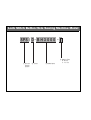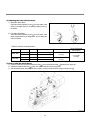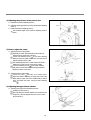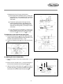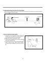
1
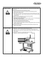
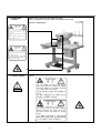
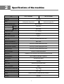
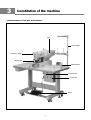
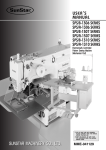
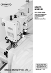
USER ’
S
MANUAL
SPS/D-BH3000
Direct Drive, Electronically
Controlled Lock Stitch
Button Hole Sewing
Machine
(Mechanical Part)
1) FOR AT MOST USE WITH EASINESS,
PLEASE CERTAINLY READ THIS MANUAL
BEFORE STARTING USE.
2) KEEP THIS MANUAL IN SAFE PLACE
FOR REFERENCE WHEN THE MACHINE
BREAKS DOWN.
SUNSTAR MACHINERY CO., LTD.
MME-060321
lity
a
u
tQ
Besst Pricevice
Be st Ser
Be
1. Thank you for purchasing our product. Based on the rich expertise and
experience accumulated in industrial sewing machine production, SUNSTAR
will manufacture industrial sewing machines, which deliver more diverse
functions, high performance, powerful operation, enhanced durability, and
more sophisticated design to meet a number of user’s needs.
2. Please read this user’s manual thoroughly before using the machine. Make
sure to properly use the machine to enjoy its full performance.
3. The specifications of the machine are subject to change, aimed to enhance
product performance, without prior notice.
4. This product is designed, manufactured, and sold as an industrial sewing
machine. It should not be used for other than industrial purpose.
R
SUNSTAR MACHINERY CO., LTD.
Lock Stitch Button Hole Sewing Machine Model
SPS / D - B H 3 0 0 0 -
④ Material Type
① Sunstar
Pattern
System
② Series
③ Model Name
G : General
K : For Knit
Contents
1. Machine Safety Regulations ......................................................................................................... 4
2. Specifications of the machine ..................................................................................................... 7
3. Constitution of the machine ......................................................................................................... 8
1) Nomenclatures of each part of the machine ..................................................................................... 8
4. Installation of the machine ............................................................................................................ 9
1) Conditions to install the machine ...................................................................................................... 9
2) Electrical installation conditions ......................................................................................................... 9
3) How to mount the table of the machine ............................................................................................. 9
4) Assembling the peripheral constituents .......................................................................................... 10
5. Preparations before operating the machine ......................................................................... 11
1) How to supply oil ............................................................................................................................. 11
2) How to attach needles ..................................................................................................................... 11
3) How to thread the upper thread ...................................................................................................... 12
4) Threading the lower thread ............................................................................................................. 12
5) How to take the bobbin case on and off ......................................................................................... 13
6) Adjusting the upper thread tension ................................................................................................. 13
7) Adjusting the upper thread sensor .................................................................................................. 13
8) Adjusting the lower thread tension .................................................................................................. 14
9) How to wind the lower thread .......................................................................................................... 14
6. How to repair the machine .......................................................................................................... 15
1) Adjusting the height of the needle bar ............................................................................................ 15
2) Adjusting the needle and the hook .................................................................................................. 15
3) Adjusting the position of hook holder .............................................................................................. 15
4) Adjusting the pressure of the presser foot ...................................................................................... 16
5) How to adjust the cutter .................................................................................................................. 16
6) Adjusting the upper thread trimmer ................................................................................................ 16
7) Adjustment of the lower thread press plate .................................................................................... 17
8) Adjustng the lower trimmer base ..................................................................................................... 17
9) Adjusting the timing of the lower thread hook plate ......................................................................... 18
10) How to adjust the bobbin capture .................................................................................................. 18
11) Adjusting the bobbin winder device ............................................................................................... 19
12) How to install and adjust a motor of direct drive type .................................................................... 19
7. Troubleshooting ............................................................................................................................ 20
8. Table ................................................................................................................................................... 21
9. Gauge List ........................................................................................................................................ 22
1) Cutter .............................................................................................................................................. 22
2) Presser Foot ................................................................................................................................... 23
3) Needle Plate ................................................................................................................................... 24
4) Feed Plate ....................................................................................................................................... 25
1
Machine Safety Regulations
Safety instruction on this manual are defined as Danger, Warning and Notice.
If you do not keep the instructions, physical injury on the human body and machine damage might be occurred.
Danger : This indication should be observed definitely. If not, danger could be happen during the installation,
conveyance and maintenance of machines.
Warning : When you keep this indication, injury from the machine can be prevented.
Notice : When you keep this indication, error on the machine can be prevented.
1-1) Machine
Transportation
Danger
1-2) Machine Installation
Warning
1-3) Machine Repair
Notice
Those in charge of transporting the machine should know the safety regulations very well.
The following indications should be followed when the machine is being transported.
ⓐ More than 2 people must transport the machine.
ⓑ To prevent accidents from occurring during transportation, wipe off the oil on the machine
well.
The machine may not work well or breakdown if installed in certain places, Install the machine
where the following qualifications agree.
ⓐ Remove the package and wrappings starting from the top. Take special notice on the nails
on the wooden boxes.
ⓑ Dust and moisture stains and rusts the machine. Install an airconditioner and clean the
machine regularly.
ⓒ Keep the machine out of the sun.
ⓓ Leave sufficient space of more than 50cm behind, and on the right and left side of the
machine for repairing.
ⓔ EXPLOSION HAZARDS
Do not operate in explosive atmospheres. To avoid explosion, do not operate this machine
in an explosive atmosphere including a place where large quantities of aerosol spray
product are being used or where oxygen is being administered unless it has been
specifically certified for such operation.
ⓕ The machine were not provided with alocal lighting due to the feature of machine.
Therefore the illumination of the working area must be fulfilled by end user.
When the machine needs to be repaired, only the assigned troubleshooting engineer educated at
the company should take charge.
ⓐ Before cleaning or repairing the machine, close down the motive power and wait 5
minutes till the machine is completely out of power.
ⓑ Not any of the machine specifications or parts should be changed without consulting the
company. Such changes may make the operation dangerous.
ⓒ Spare parts producted by the company should only be used for replacements.
ⓓ Put all the safety covers back on after the machine has been repaired.
4
1-4) Machine Operation
Warning
1-5) Devices for Safety
Notice
SPS/D-BH3000 Series is made to sew button hole on fabrics and other similar material for
manufacturing.
Follow the following indications when operating the machine.
ⓐ Read through this manual carefully and completely before operating the machine.
ⓑ Wear the proper clothes for work.
ⓒ Keep hands or other parts of the body away from the machine operation parts (needle,
hook, thread take-up lever, cutter and upper thread trimmer mes etc.) when the machine
is being operated.
ⓓ Keep the covers and safety plates on the machine during operation.
ⓔ Be sure to connect the earthing conductor.
ⓕ Close down the electric motive power and check if the switch is turned“off”before opening
electric boxes such as the control box.
ⓖ Stop the machine before threading the needle or checking after work.
ⓗ Do not step on the pedal when turning the power on.
ⓘ Do not insert multiple motor plugs into one electric outlet.
ⓙ If possible, install the machine away from source of strong electrical noise such as high
frequency welding machines
Be careful when the presser foot comes down to press. Otherwise, the finger or hand
might be hurt at smacking.
ⓐ Safety label : It describes cautions duing operating the machine.
ⓑ Thread take-up cover : It prevents from any contact beween body and take-up lever.
ⓒ Motor cover: It is a protective device against potential accidents which might occur during
motor's rotation.
ⓓ Finger guard : It prevent from contacts between a finger and needle.
ⓔ Safety plate : It protects eyes against needle breaks.
ⓒ
ⓑ
ⓐ
ⓔ
ⓓ
5
1-6) Caution Mark
Position
Caution mark is attached on the machine for safety.
When you operate the machine, observe the directions on the mark.
Position of Warning Mark
CAUTION
경 고
Do not operate without finger guard and
safety devices. Before threading, changing
bobbin and needle, cleaning etc. switch off
main switch.
손가락 보호대와 안전장치 없이 작동하지
마십시오.
실, 보빈, 바늘교환시나 청소전에는 반드시 주
전원의 스위치를 꺼 주십시오.
CAUTION
경 고
Hazardous voltage will cause injury.
Be sure to wait at least 360 seconds before
opening this cover after turn off main switch
and unplug a power cord.
고압 전류에 의해 감전될 수 있으므로 커버를
열 때는 전원을 내리고 전원 플러그를 뽑고 나
서 360초간 기다린 후 여십시오.
1-7) Contents of Marks
Caution
1)
CAUTION
경 고
Do not operate without finger guard
and safety devices. Before threading,
changing bobbin and needle, cleaning
etc. switch off main switch.
Warning
손가락 보호대와 안전장치 없이 작동하지 마
십시오.
실, 보빈, 바늘교환시나 청소전에는 반드시
주전원의 스위치를 꺼 주십시오.
2)
CAUTION
경 고
Hazardous voltage will cause injury.
Be sure to wait at least 360 seconds
before opening this cover after turn
off main switch and unplug a power
cord.
고압 전류에 의해 감전될 수 있으므로 커버
를 열 때는 전원을 내리고 전원 플러그를 뽑
고 나서 360초간 기다린 후 여십시오.
6
3)
2
Specifications of the machine
Item
SPS/D-BH3000G
Stitch type
SPS/D-BH3000K
Lock stitch
Knit suits such as sweater, gardigun,
under ware, lingerie, etc.
General fabrics such as shirts, blouse,
working dress, lady s dress
Usage
Maximum sewing speed
Max. 4,000spm
Width
Max. 6mm
Length
Max. 40mm
Area of buttonhole
Length of the cutter
6.4 ~ 31.8mm
DPx5 #11
Using needle
Stroke of the needle bar
Using hook
35mm
DP-Type Full Rotation (Standard) Hook
Ascent of the presser bar
Max. 13mm
Raising type of the presser bar
Driven by a 5-phase stepping pulse motor
Drive type of the Y-transfer
Driven by a 5-phase stepping pulse motor
Zigzag drive type
Driven by a 5-phase stepping pulse motor
Drive type of the cutter
Driven by a double tuned solenoid
Safety device
Provided patterns
Available to use an emergency stop function during the sew work
Max. 99 patterns (Standard : 4 patterns)
No. of stitches
768 stitches per pattern
Memory
Using motor
EP-ROM
Direct drive type AC servo-motor
Power consumption
600VA
Proper temperature of machine running
5
Proper relative humidity of machine running
20% ~ 80%
Voltage
~ 40
1-phase:100~240V, 3-phase:200~440V. 50/60Hz
Oil supply
Automatic
7
3
Constitution of the machine
1) Nomenclatures of each part of the machine
Arm
Thread Stand
Emergency switch
Safety plate
Operation Box
Power Switch
Control Box
Pedal
8
4
Installation of the machine
1) Conditions to install the machine
A. To prevent any accident caused by a malfunction, do not use the machine where the voltage is over the rated one 10%.
B. For safe operation of the machine, use it under the following conditions.
Ambient temperature during operation : 5 ~ 40
Ambient temperature during preservation : -10 ~ 60
C. Relative humidity : Within a range of 20 ~ 80% (Relative speed)
2) Electrical installation conditions
A. Electrical power supply voltage
The electrical power supply voltage shall be within a range of the rated 10%.
It is highly recommended that the electrical power frequency shall be within a range of the rated (50/60Hz) 1%.
B. Electron noise
It is highly recommended that an independent electrical power outlet separated from the products of a strong magnetic
field and high frequency shall be used and keep apart from such products.
C. Be sure to apply a low voltage when attaching the supplementary devices and accessories to the controller
D. Take care not to have water, coffee, etc. spill into the control box and the motor.
E. Do not drop the control box and the motor.
Cautions
Those in charge of installing the machine should understand
the safety regulations and rules very well.
Please commit the electrical wiring work to your SUNSTAR
wholesaler or distributor or an electrical technician.
The weight of the machine is more than 40kg.
More than 2 people must install it.
Do not connect the electrical power plug until the installation
has been finished. If you work a pedal by mistake, the machine
shall operate, which shall cause an injury.
Be sure to connect the grounding conductors. The improper
connection can give a cause to electrical shock or malfunction.
Please mount the belt covers on the machine head part and the
motor.
3) How to mount the table of the machine
A. Fix the control box
the table.
and the electric power switch
on
①
④
③
B. Place the oil pan on the position marked on the table and
fix the bed hinge bracket on the hole.
⑤
[Caution] Loosely fasten the clamping bolt of the bed hinge
bracket and tighten it completely after joining it with the bed
hinge shaft.
C. Place the sewing machine bed on the oil pan . Adjust the
and the
position of the bed and joint the bed hinge pad
bed hinge bracket , using the bed hinge shaft . Tighten
the fastening screw of the hinge shaft.
②
[ Fig. 1 ]
③
[Danger]
Make sure that the sewing machine is moved by at least
two persons to prevent any possible accidents.
D. Fix the bed hinge bracket on the table by completely
fastening the clamping bolt of the bracket. Lay the rear part
of the sewing machine to the side and fix the oil pan on the
table, using the screw .
⑧
⑤
⑦
⑧
[ Fig. 2 ]
9
4) Assembling the peripheral constituents
A. Atach the motor cover to the back side of the machine by
using fixing bolts (4 EA).
Motor Cover Supporter
②
①
[ Fig. 3 ]
B. Attach the safety plate to the back side of the arm.
Face Plate
[Cautions]
To prevent any accidents related to safety, be sure to
attach those while working.
②
Safety Plate
①
[ Fig. 4 ]
C. Install the thread stand ③ on the table.
③
D. Drive the head part supporting rod ④ into the table by
beating.
[Cautions]
Drive the head part supporting rod ④ into the table by
beating until its end perfectly.
If it has not been driven until its end perfectly, it will be
unsafe and danger when the head part is lay down.
④
[ Fig. 5 ]
10
5
Preparations before operating the machine
1) How to supply oil
A. Lay down the machine head part, and supply oil until the
description line of HIGH slowly.
Supplement oil immediately when the oil surface is lowering
on the description line of <LOW>.
[ Fig. 6 ]
B. Be sure to supply oil into the oil inlet port on the upper side of
the arm when the machine is used at the first or has not
been used for a long time.
Sillicon Tank
[ Fig. 7 ]
2) How to attach needles
Move the needle bar to the highest position turning the hand
pulley, and unfasten the needle fixing screw
in the needle
bar, and pull a needle into until that the upper end meets the end
of the needle inserting port in the state that the long groove of
needle faces forward, and then fix it using the needle fixing
screw .
②
[Caution]
Required needles: DP 5#11
①
[ Fig. 8 ]
11
3) How to thread the upper thread
Place the thread take-up level on the highest position, and then hang up the upper thread as shown in Fig. 9.
In case of the thread guide of the needle bar, hang up the upper thread as shown in Fig. 9 according to the kinds of thread.
The proper length of the upper thread that puts forward from the thread hole of the needle is about 40mm from the needle.
[ Cotton and Span ]
[ Polyester ]
[ Fig. 9 ]
4) Threading the lower thread
A. Insert the bobbin
into the bobbin case
as shown in Fig.10.
[Cautions]
If the bobbin is inserted by reversing the front and the
back, it will run idle. Therefore, be sure to insert it by
turning clockwise when seen from behind the bobbin case.
of the bobbin
B. Pull out the lower thread from the groove
passing
case, and then thread it through the thread hole
below the tension spring . Take out about 40mm of the
thread through the thread hole for Whip Stitch, and take out
the same length through the thread hole for Pure Stitch.
Whip Stitch (Plain Stitch)
Whip Stitch is a stitching type that the upper thread moves
vertically on the sewing material with the zigzag shape. This
type is the same thing with the zigzag type of the drop feed
zigzag machine.
⑦ Whip Stitch
⑥ Pure Stitch
①
②
④
⑤
③
[ Fig. 10 ]
Pure Stitch (Seal Stitch)
Pure Stitch is a stitching type that while the upper thread is going along straight with the center of the sewing line by
varying the upper thread tension, the lower thread twists up with it in lateral.
12
5) How to take the bobbin case on and off
Hold the knob of bobbin case, and push it into the shuttle until
it makes a sound.
[ Cautions ]
If you start operating the machine under the state that the
bobbin case is not perfectly installed, the thread will be
entangled or the bobbin case will be protruded.
①
[ Fig. 11 ]
6) Adjusting the upper thread tension
A. The tension of the upper thread will become hardened if you
turn the tension adjusting nuts , & of the main thread
& the
controller , the supplementary thread controller
supplementary thread controller (Bottom) clockwise, and
the tension of the upper thread will become loosened, if you
turn those counterclockwise, as shown in Fig. 12. Please
the thread tension in conformity with the actual conditions
since it is dependent on the sewing conditions including
sewing materials, threads, number of stitches, etc.
B. The tension of the thread take-up spring will be adjusted that
it will become hardened if you turn the shaft terminal groove
clockwise using a
of the thread tension controller
screwdriver and it will become loosened if you turn it
counterclockwise.
③
②
⑥
①
④
⑦
⑤
[ Fig. 12 ]
7) Adjusting the upper thread sensor
A. Unfasten the joint screw of the thread sensor pin in status
that a thread does not hang on the thread take-up spring,
and adjust to contact the thread take-up spring and the
sensor plate, and then fasten the joint screw.
B. Adjust to contact the thread spring and the sensor plate
certainly regulating the positions of the thread sensor plate
even when the stroke of the thread take-up spring has been
changed.
Thread take-up spring
Thread sensor plate
Joint screw
[Cautions]
Pay your attention not to contact any other metals on the
thread sensor plate except for the thread take-up spring.
It runs a chance of failure to detect thread.
Adjust the distance between the thread
feed spring and the loop taker to make
it 2mm.
13
[ Fig. 13 ]
8) Adjusting the lower thread tension
A. Whip Stitch (Plain Stitch)
Adjust the tension adjusting screw until the bobbin case
drops by its weight when you are waving it taking the end of
the thread.
①
B. Pure Stitch (Seal Stitch)
Adjust the tension adjusting screw until the bobbin case
starts dropping slowly by its weight when you are taking the
end of the thread.
[ Fig. 14 ]
※Reference data for the thread tensions
Stitch type
Whip stitch
Pure stitch
Upper thread Lower thread Tension of the upper thread Tension of the lower thread
Polyester #50 Polyester #50
Span #60
Span #60
Polyester #50 Polyester #50
Span #60
Span #60
0.30~0.70N(30~70g)
0.15~0.25N
(15~25g)
0.50~0.85N(50~85g)
0.75~2.00N(75~200g)
0.05~0.15N
(5~15g)
1.00~2.20N(100~220g)
Tension of the thread
take-up spring
0.10~0.20N
(10~20g)
9) How to wind the lower thread
A. Insert the bobbin into the thread winder drive shaft on the thread winder base attached to the upper cap.
B. Adhere the bobbin winder lever closely to a bobbin, and then let the machine run.
C. After the bobbin winder lever takes off from a bobbin, cut off the thread of bobbin using the winder mes .
②
③
④
①
[ Fig. 15 ]
14
6
How to repair the machine
1) Adjusting the height of the needle bar
A. Lower the needle bar ① to the lowest position.
B. Unfasten the joint screw ③ on the needle clamp after
removing the plate rubber cap ②.
C. After inserting the part of the needle bar setting gauge ④
between the lower plate of the needle and the upper plate of
the needle plate, adjust the height of the needle bar.
D. After fastening the joint screw on the needle bar clamp,block
it with the plate rubber cap ②.
②③
④
①
[ Fig. 16 ]
2) Adjusting the needle and the hook
A. Fasten the joint screw on the hook joint ①.
B. Raise the needle bar ② from the lowest position by using the hand pulley, and insert the part 2 of the needle bar setting
gauge ④ between the needle bar lower plate and the needle plate ③ upper plate, as shown in Fig. 13.
C. Fasten so that the hook point and the center of the needle meet together when the thread rod touches the thread rod
setting gauge ④.
D. Loosen the fastening screw and adjust the hook to make the distance between the hook point and the needle 0.01
~0.08mm.
②
④
①
0.01~0.08
⑤
Distance between the needle
center and the hook point
③
[ Fig. 17 ]
3) Adjusting the position of hook holder
Loosen the fastening screw ①. Adjust so that the needle and
the right side of the hook holder meet part A of the hook and
fasten the screw ①.
②
①
[ Fig. 18 ]
15
4) Adjusting the pressure of the presser foot
A. Unfasten the pressure adjusting screw ①.
B. Adjust the pressing pressure by turning the pressure adjusting
screw ②.
C. Fasten the pressure adjusting screw ①.
The standard height of the pressure adjusting screw is
30mm.
②
30mm
①
[ Fig. 19 ]
5) How to adjust the cutter
④
A. Adjustment of the cutter position
Separate the cutter solenoid shaft and the cutter link
bracket from the upper part of the Arm.
Loosen the fastening screw
of the cutter adhering
plate and move the cutter holder to the front and back to
adjust the position of the cutter.
The standard position of the cutter is where its end is a
distance of 2.2 mm from the center of the needle.
Loosen the fastening screw of the cutter adhering
plate and move the cutter holder to the right and left to
adjust the position of the cutter.
③
Top of needle
Plate
Lowest
Position
① ②
2.2mm
B. Adjustment of the cutter height
Lower the cutter
manually to its lowest point.
Adjust the distance between the upper part of the cutter
blade and the upper side of the needle plate to make it
3mm, and fasten the cutter, using the cutter fastening
screw .
3mm
2.2mm
[ Fig. 20 ]
6) Adjusting the upper thread trimmer
A. Adjusting the height of the thread trimmer mes.
Unfasten the joint screw ①.
After adjusting the interval between the thread trimmer
fixing mes ② and the presser foot to be 0.5mm, fasten
the joint screw ①.
②
①
③
0.5mm
[ Fig. 21 ]
16
B. Adjusting the timing of the upper thread trimmer
After shutting off the preparation lamp by pressing the
preparation key in the operation box, press the
presser foot key to contact the presser foot on the
needle plate.
①
②
To adjust the opening speed of the upper trimmer,
loosen the tightening screw ③ and adjust the open
cam A ④ left or right to set the distance between the
upper trimmer's moving blade ① and the open cam B
② at 0.5mm.
The opening timing is adjusted by correcting the
distance between the lever return plate of the upper
thread trimmer and the return cap to be 2mm.
③
③
④
Approx. 0.5mm
②
7) Adjustment of the lower thread press plate
⑦
1mm
A. Loosen the fastening screw of the lower thread press plate.
Adjust the distance between the lower thread press plate and
the center of the needle hole to make it 2 ~ 3mm.
B. Tighten the fastening screw
of the lower thread press
plate.
⑤
2mm
⑥
About 3mm
2mm
[ Fig. 22 ]
[ Fig. 23 ]
8) Adjustng the lower trimmer base
A. Place the end part of the under thread presser ① on A
exactly.
A
B. Move the mes automatic lever ② arrow-directionally to
touch the lower thread trimmer's moving blade on B.
with the roller of
C. Adjust to touch the lower thread cover
the lower hook plate by fastening the joint screw of the
lower thread cover and then fasten the joint screw .
⑤
④
B
③
Roller
①
[ Fig. 24 ]
17
9) Adjusting the timing of the lower thread hook plate
Adjust to correct the right end of the transfer arm support and the punched mark on the Y-transfer axis exactly by unfastening
the joint screw of the transfer arm support.
① Punched mark
Transfer axis
Lower thread plate
①
[ Fig. 25 ]
10) How to adjust the bobbin capture
A. After shutting off the preparation lamp by pressing the
preparation key in the operation box, press the presser foot
key to contact the presser foot on the needle plate.
B. Unfasten the joint screw of the bobbin capture.
C. Adjust to put the contacting surface of the bobbin capture
into the hole of the bobbin case.
D. After making sure that the presser foot has placed its original
position, unfasten the nut . Adjust to correct the distance
from the bed edge to be 12.5mm by turning the joint screw
.
②
12.5
③
①
④
[ Fig. 26 ]
18
11) Adjusting the bobbin winder device
A. When the quantity of thread to be wound is big, unfasten
the joint screw on the thread winder adjusting plate and
turn it to A-direction by using the initial position of the
thread winder adjusting plate. And when the quantity is
small, get it turned to B-direction.
B. Adjust the position of the bobbin winding driving wheel to
make it a distance of 1mm from the upper collar and a
distance of 8mm from the hand pulley driving gear. Tighten
the fastening screw.
Bobbin Winder Adjusting Plate
Hand Pulley
Driving Gear
Bobbin Winder
Driving Wheel
8mm
1mm
Upper Shaft Collar
Upper Shaft Bushing
[ Fig. 27 ]
12) How to install and adjust a motor of direct drive type
A. Under the state that the joint screw no. 1 when attaching a
coupling to the servo motor is positioned correctly at the
surfacing part of the servo motor, adjust to make the interval
between the coupling and the servo motor to be 0.7mm and
then fasten the joint screw no. 1 of the coupling.
B. Under the state that the joint screw no. 1 of coupling when
attaching a coupling to the upper shaft is positioned
correctly at the surfacing part of the upper shaft, adhere it
toward the back bearing O-Ring in the upper shaft and
fasten the coupling no.1 joint screw. (The distance is about
2mm).
C. Take care to connect the two couplings by matching the
positions of joint screws each other.
If the positions of the coupling joint screws do not match
correctly each other, the needle will not stop at the
normal position.
No. 1 joint screw
Servo motor
O-Ring
Upper shaft
Surfacing part
Back bearing
on the upper
shaft
ARM
②
Coupling
0.7
[ Fig. 27 ]
19
7
Troubleshooting
Pleas examine the following items before applying repair and after service.
If you cannot solve the problem using these resources, please inquire your SUNSTAR distributor after shutting the electric power off.
Danger
Please turn off the electric switch and unplug the electric outlet before working.
If you work the pedal, it will give a cause to harm on your body by operating the machine.
No.
Description
1
Abnormalities on the
machine starting and
operation
2
3
Bad stopping
position
Needle break
Check and Cause
Solution
The belt tension has got loosened too much or the belt
Adjust the belt tension or exchange it.
is ruptured.
Fuse shortage for the electric power or the circuit
Confirm the fuse shortage of the main shaft motor
drive in the control box and then exchange it.
The main drive belt has got loosened.
Adjust the belt tension.
Damaged needle (The needle has got twisted in or the
needle hole, groove or end has got worn or deformed.)
Exchange the needle.
A wrong mounting of the needle
Contacting the needle with the hook.
Mount the needle correctly.
Adjust the interval between the needle and the hook.
A wrong threading.
Thread it correctly.
A wrong mounting of needle(Needle height, direction, etc.) Mount the needle again.
4
Thread cutting
Damaged needle(The needle has got twisted in or the
needle hole, groove or end has got worn or deformed.)
Exchange the needle.
Strong tensions of the upper thread and the lower thread.
Adjust the tensions.
Adjust the tension and the stroke of the thread take-up Adjust the tension of the thread take-up spring and the
spring
movements.
5
6
7
Stitch skipping
Bad thread tightening
Error in trimming
A wrong wire connection of the thread sensor plate.
Connect the wire with the thread sensor plate again.
Twisted needle is used.
Improper size of the needle compared with the used
thread
Exchange the needle.
Bad mounting of the needle.
Mount the needle again.
Improper timing of the needle and the hook.
A broad interval between the needle groove and the
shuttle point.
Adjust the timing of the needle and the hook again.
An excessive tension and movement of the thread
take-up spring.
Adjust the tension of the thread take-up spring and the
movements.
The tension of upper thread is weak.
Adjust the upper thread tension.
The tension of lower thread is weak.
Adjust the lower thread tension.
Exchange the needle.
Adjust the needle drop point again.
Improper timing of the needle and the hook.
Adjust the timing of the needle and the hook again.
The crossing tension between the moving mes and
Adjust the fixing mes tension.
the fixing mes has got loosened.
The knife edges of the moving mes and the fixing mes
Exchange the moving mes and the fixing mes.
have got worn.
20
8
Table
21
9
Gauge List
1) Cutter
Cutter(1/4 )
28-064A-300G
Cutter(3/8 )
28-054A-300G
Cutter(7/16 )
28-065A-300G
Cutter(1/2 )
28-053A-300G
Cutter(9/66 )
28-066A-300G
Cutter(5/8 )
28-055A-300G
Cutter(11/16 )
28-067A-300G
Cutter(3/4 )
28-068A-300G
Cutter(13/16 )
28-069A-300G
Cutter(7/8 )
28-070A-300G
Cutter(1 )
28-056A-300G
Cutter(1⅛ )
28-071A-300G
Cutter(1¼ )
28-057A-300G
22
2) Presser Foot
Presser Foot General (G)
Presser Foot (Down)-16mm(G)
Presser Foot Knit (K)
20-529A-300G
Presser Foot (Down)-16mm(K)
20-536A-300G
Presser Foot (Down)-25mm(G)
20-523A-300G
Presser Foot (Down)-25mm(K)
20-525A-300G
Presser Foot (Down)-32mm(G)
20-533A-300G
Presser Foot (Down)-32mm(K)
20-538A-300G
23
3) Needle Plate
Needle Plate General (G)
Needle Plate Knit (K)
Needle Plate(General)-1.2mm(G)
10-130A-300G
Needle Plate(Knit)-1.2mm(K)
10-112A-300G
Needle Plate(General)-1.4mm(G)
10-111A-300G
Needle Plate(Knit)-1.4mm(K)
10-132A-300G
Needle Plate(General)-1.6mm(G)
10-131A-300G
Needle Plate(Knit)-1.6mm(K)
10-133A-300G
24
4) Feed Plate
Feed Plate General (G)
Feed Plate Knit (K)
20-043A-300G
20-044A-300K
25