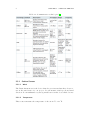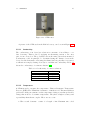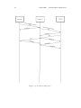
1
Instituto Superior de Engenharia do Porto
Departamento de Engenharia Electrotécnica
Rua Dr. António Bernardino de Almeida, 431, P-4200-072 Porto
Environmental/Regatta Buoy:
Telemetry and Configuration
Erasmus Project/Internship Thesis
MSc. in Electrical Engineering and Computers
Laurens Allart
Supervisors: Mrs Benedita Malheiro
Mr Paulo Ferreira
Mr Manuel Silva
Mr Pedro Guedes
Academic Year: 2013-2014
Resumo
A monitorização ambiental é essencial para a tomada de decisões tanto na ciência como na indústria. Em particular, uma vez que a água é essencial à vida e
a superfı́cie da Terra é composta principalmente por água, a monitorização do
clima e dos parâmetros relacionados com a água em ecossistemas sensı́veis, tais
como oceanos, lagoas, rios e lagos, é de extrema importância.
Um dos métodos mais comuns para monitorar a água é implantar boias. O
presente trabalho está integrado num projeto mais amplo, com o objetivo de projetar e desenvolver uma boia autónoma para a investigação cientı́fica com dois
modos de funcionamento: (i) monitorização ambiental ; e (ii) baliza ativa de regata. Assim, a boia tem duas aplicações principais: a coleta e armazenamento
de dados e a assistência a regatas de veleiros autónomos.
O projeto arrancou há dois anos com um grupo de quatro estudantes internacionais. Eles projetaram e construı́ram a estrutura fı́sica, compraram e montaram
o sistema de ancoragem da boia e escolherem a maioria dos componentes eletrónicos para o sistema geral de controlo e medição. Este ano, durante o primeiro
semestre, dois estudantes belgas - Jeroen Vervenne e Hendrick Verschelde - trabalharam nos subsistemas de recolha e armazenamento de dados (unidade de
controlo escrava) e de telemetria e configuração (unidade de controlo mestre) assim como definiram o protocolo de comunicação da aplicação. O trabalho desta
tese continua o desenvolvimento do subsistema de telemetria e configuração. Este
subsistema é responsável pela configuração do modo de funcionamento e dos sensores assim como pela comunicação com a estação de base (controlo ambiental),
barcos (baliza ativa de regata) e com o subsistema de recolha e armazenamento
de dados. O desenvolvimento do subsistema de recolha e armazenamento de dados, que coleta e armazena num cartão SD os dados dos sensores selecionados,
prossegue com outro estudante belga - Mathias van Flieberge.
iii
O objetivo desta tese é, por um lado, implementar o subsistema de telemetria e de configuração na unidade de controle mestre e, por outro lado, refinar e
implementar, conjuntamente com Mathias van Flieberge, o protocolo de nı́vel de
aplicação projetado. Em particular, a unidade de controlo mestre deve processar
e atribuir prioridades às mensagens recebidas da estação base, solicitar dados à
unidade de controlo escrava e difundir mensagens com informação de posição e
condições de vento e água no modo de regata. Enquanto que a comunicação entre
a unidade de controlo mestre e a estação base e a unidade de controlo mestre e os
barcos é sem fios, a unidade de controlo mestre e a unidade de controlo escrava
comunicam através de uma ligação série.
A boia tem atualmente duas limitações: (i) a carga máxima é de 40 kg; e
(ii) apenas pode ser utilizada em rios ou próximo da costa dada à limitação de
distância imposta pela técnica de comunicação sem fios escolhida.
Abstract
Environmental monitoring is essential for decision-making both in science and
industry. In particular, since water is essential to life and the Earth’s surface
consists mostly of water, monitoring the weather and water-related parameters
in sensitive ecosystems such as oceans, lagoons, rivers and lakes is of the greatest
importance.
One of the most commons methods to monitor water is to deploy buoys. The
current work is part of a larger project with the aim to design and develop a
dual mode autonomous buoy for scientific research: (i) environmental monitoring; and (ii) regatta beacon. As a result, the buoy has two major applications:
collection and storage of data and assistance in autonomous sailing boat regattas.
The project started two years ago with a group of four international students.
They designed and built the physical structure and selected and assembled the
anchoring system of the buoy. They also chose the majority of the components
for the overall control and sensing system. This year, during the first semester,
two Belgian students - Jeroen Vervenne and Hendrick Verschelde - worked on the
data logging (slave control unit) as well as on the telemetry and configuration
(master control unit) subsystems and designed the application level communication protocol. The current thesis continues the development of the telemetry and
configuration subsystem. This subsystem is responsible for the configuration of
the operation mode and selection of sensors, as well as for the communication
with the base station (environmental monitoring), boats (regatta beacon) and
with the data logging subsystem. The development of the data logging subsystem, which collects and stores in a SD card the selected sensor data, proceeds
with another Belgian student - Mathias van Flieberge.
The goal of this thesis is to implement the telemetry and configuration subsystem in the master control unit and to refine and implement, together with
v
Mathias van Flieberge, the designed application level protocol. In particular the
master control unit must handle and assign priorities to the incoming messages
from the base station, request data from the slave control unit and broadcast
messages holding water, wind and position real time data in the regatta mode.
Whereas the master control unit and base station communication and the master
control unit and boat communication is wireless, the master and the slave units
communicate over a serial connection. The buoy has currently two limitations: (i)
the maximum payload is 40 kg; and (ii) it can only be used in rivers or near shore
due to the distance limitation of the chosen wireless communication technique.
Samenvatting
Het monitoren van de geografische omgeving is essentieel om belangrijke beslissingen te nemen in zowel wetenschappelijke middens als in de industrie. Omdat
water in het bijzonder noodzakelijk is voor de mogelijkheid tot leven en omdat
het grootst deel van het aardoppervlak bestaat uit water, is het van groot belang
weersomstandigheden en water gerelateerde parameters te bestuderen in gevoelige
ecosystemen zoals oceanen, lagunes, meren en rivieren.
In van de meest voorkomend methodes om water te bestuderen is het gebruik
van boeien. Dit werk zal dan ook voort bouwen op een deel van een groter project
dat tot doel heeft om een autonome boei te ontwikkelen voor wetenschappelijk
onderzoek die 2 verschillende modes kan hanteren. Een mode die zorgt voor het
monitoren van de omgeving en een mode die zich gedraagt als een regatta beacon.
Als gevolg hiervan heeft de boei twee belangrijke toepassingen: Het verzamelen
en opslaan van data en het bieden van assistentie in een autonome boten race.
Het project werd twee jaar geleden gestart met een groep van vier internationale studenten. Zij hebben de fysische structuur ontworpen en gebouwd en ze
hebben ook het bevestigingssysteem van de boei geselecteerd en samen gesteld.
Verder hebben deze studenten ook de meerderheid van de componenten gekozen
voor de algemene controle en het sensor systeem. Dit jaar tijdens het eerste
semester hebben twee Belgische studenten, Jeroen Vervenne en Hendrick Verschelde, verder gewerkt aan dit project. De ene aan het data logging gedeelte
(slave module), de andere aan het telemetrie en configuratie gedeelte (master
module). Zij definieerden ook het application level communication protocol. Deze
thesis bouwt verder op de ontwikkeling van het telemetrie en configuratie subsysteem. Dit subsysteem is verantwoordelijk voor de configuratie van de operatie
mode en het selecteren van sensoren, maar ook voor de communicatie tussen het
base station (environmental monitoring), de boten (regatta beacon) en het data
logging subsysteem. Het uitwerken van het data logging subsysteem, dat sensor
vii
data vergaart en op slaat op een SD kaart, wordt gedaan door een andere Belgische student, Mathias Van Flieberge.
Het doel van deze thesis is het implementeren van het telemetry en configuratie subsysteem in een master control unit en om verder uitwerken en implementeren van het ontworpen application level protocol, samen met Mathias Van
Flieberge. In het bijzonder moet de master module in staat zijn om inkomende
berichten van het base station te behandelen en een prioriteit toe te kennen. Hij
moet informatie kunnen vragen aan de slave module en in regatta mode moet
hij real-time data kunnen broadcasten naar andere modules. De communicatie
tussen de master unit en het base station en de master unit en een autonome
boot moet gebeuren aan de hand van een draadloze verbinding, de communicatie
tussen de master module en de slave module gebeurt aan de hand van een seriële
connectie.
De boei heeft momenteel twee beperkingen: (i) de maximale lading bedraagt
veertig kilogram en (ii) ze kan enkel gebruikt worden in rivieren of dicht bij de
kust door de beperkingen die de keuze van de gebruikt draadloze communicatie
technologie oplegt.
Contents
Contents
i
List of Figures
v
List of Tables
vii
Glossary
ix
Acknowledgments
xi
1 Introduction
1.1 Presentation . . . . . . . . . . . .
1.2 Motivation . . . . . . . . . . . .
1.3 General Information . . . . . . .
1.4 Project Description . . . . . . . .
1.4.1 General Objective . . . .
1.4.2 Environmental Mode . . .
1.4.3 Regatta Mode . . . . . .
1.4.4 Objectives Regarding The
. . . . . . . . .
. . . . . . . . .
. . . . . . . . .
. . . . . . . . .
. . . . . . . . .
. . . . . . . . .
. . . . . . . . .
Master Module
2 State of The Art
2.1 Introduction . . . . . . . . . . . . .
2.2 Communication . . . . . . . . . . .
2.3 Sensors . . . . . . . . . . . . . . .
2.3.1 Surface Sensors . . . . . . .
2.3.1.1 Wind . . . . . . .
2.3.1.2 Temperature . . .
2.3.1.3 Air Pressure . . .
2.3.1.4 Precipitation . . .
2.3.1.5 Relative Humidity
2.3.1.6 Solar Radiation .
i
.
.
.
.
.
.
.
.
.
.
.
.
.
.
.
.
.
.
.
.
.
.
.
.
.
.
.
.
.
.
.
.
.
.
.
.
.
.
.
.
.
.
.
.
.
.
.
.
.
.
.
.
.
.
.
.
.
.
.
.
.
.
.
.
.
.
.
.
.
.
.
.
.
.
.
.
.
.
.
.
.
.
.
.
.
.
.
.
.
.
.
.
.
.
.
.
.
.
.
.
.
.
.
.
.
.
.
.
.
.
.
.
.
.
.
.
.
.
.
.
.
.
.
.
.
.
.
.
.
.
.
.
.
.
.
.
.
.
.
.
.
.
.
.
.
.
.
.
.
.
.
.
.
.
.
.
.
.
.
.
.
.
.
.
.
.
.
.
.
.
.
.
.
.
.
.
.
.
.
.
.
.
.
.
.
.
.
.
.
.
.
.
.
.
.
.
.
.
.
.
.
.
.
.
.
.
.
.
.
.
.
.
.
.
.
.
.
.
.
.
.
.
.
.
.
.
.
.
.
.
.
.
.
.
.
.
.
.
.
.
.
.
.
.
.
.
.
.
.
.
1
1
1
1
2
3
4
4
4
.
.
.
.
.
.
.
.
.
.
5
5
6
7
8
8
8
9
9
10
10
ii
CONTENTS
2.3.2
2.4
2.5
Oceanographic Sensors . . . . . . . . . . . . . . . . . . . . .
2.3.2.1 CTD . . . . . . . . . . . . . . . . . . . . . . . . .
2.3.2.2 Chemical Substance Detectors . . . . . . . . . . .
2.3.2.3 Water Velocity . . . . . . . . . . . . . . . . . . . .
2.3.2.4 Water Turbidity . . . . . . . . . . . . . . . . . . .
2.3.2.5 Water pH . . . . . . . . . . . . . . . . . . . . . . .
2.3.2.6 Algae and Plankton . . . . . . . . . . . . . . . . .
Related Work . . . . . . . . . . . . . . . . . . . . . . . . . . . . . .
2.4.1 Autonomous Meteorological Buoy . . . . . . . . . . . . . .
2.4.2 Technology, Design, and Operation of an Autonomous Buoy
System in the Western English Channel . . . . . . . . . . .
2.4.3 Implementation of Embedded System for Autonomous Buoy
Conclusion . . . . . . . . . . . . . . . . . . . . . . . . . . . . . . .
3 Available Equipment
3.1 Hull and Steel Structure . . . . . . .
3.2 Raspberry Pi . . . . . . . . . . . . .
3.2.1 Specifications . . . . . . . . .
3.2.2 Controlling the Raspberry Pi
3.2.3 Setting up the Raspberry Pi .
3.3 STM32F3 Discovery . . . . . . . . .
3.4 Serial Communication . . . . . . . .
3.5 Sensors . . . . . . . . . . . . . . . .
3.5.1 CTD . . . . . . . . . . . . . .
3.5.1.1 Conductivity . . . .
3.5.1.2 Temperature . . . .
3.5.1.3 Pressure . . . . . .
3.5.2 Anemometer . . . . . . . . .
3.5.3 GNSS . . . . . . . . . . . . .
3.6 Conclusion . . . . . . . . . . . . . .
4 Project Development Tools
4.1 Operating Systems . . . . . . .
4.1.1 Raspbian . . . . . . . .
4.1.2 ChibiOS . . . . . . . . .
4.2 Programming Languages . . . .
4.2.1 Python . . . . . . . . .
4.3 Software . . . . . . . . . . . . .
4.3.1 X11 . . . . . . . . . . .
4.3.2 SSH . . . . . . . . . . .
4.3.3 CoolTerm . . . . . . . .
4.3.4 CheckSum and ModeOn
.
.
.
.
.
.
.
.
.
.
.
.
.
.
.
.
.
.
.
.
.
.
.
.
.
.
.
.
.
.
.
.
.
.
.
.
.
.
.
.
.
.
.
.
.
.
.
.
.
.
.
.
.
.
.
.
.
.
.
.
.
.
.
.
.
.
.
.
.
.
.
.
.
.
.
. . . . . . . .
. . . . . . . .
. . . . . . . .
. . . . . . . .
. . . . . . . .
. . . . . . . .
. . . . . . . .
. . . . . . . .
. . . . . . . .
Applications
.
.
.
.
.
.
.
.
.
.
.
.
.
.
.
.
.
.
.
.
.
.
.
.
.
.
.
.
.
.
.
.
.
.
.
.
.
.
.
.
.
.
.
.
.
.
.
.
.
.
.
.
.
.
.
.
.
.
.
.
.
.
.
.
.
.
.
.
.
.
.
.
.
.
.
.
.
.
.
.
.
.
.
.
.
.
.
.
.
.
.
.
.
.
.
.
.
.
.
.
.
.
.
.
.
.
.
.
.
.
.
.
.
.
.
.
.
.
.
.
.
.
.
.
.
.
.
.
.
.
.
.
.
.
.
.
.
.
.
.
.
.
.
.
.
.
.
.
.
.
.
.
.
.
.
.
.
.
.
.
.
.
.
.
.
.
.
.
.
.
.
.
.
.
.
.
.
.
.
.
.
.
.
.
.
.
.
.
.
.
.
.
.
.
.
.
.
.
.
.
.
.
.
.
.
.
.
.
.
.
.
.
.
.
.
.
.
.
.
.
.
.
.
.
.
.
.
.
.
.
.
.
.
.
.
.
.
.
.
.
.
.
.
.
.
.
.
.
.
.
.
.
.
.
.
.
.
.
.
.
.
.
.
.
.
.
.
.
.
.
.
.
.
.
.
10
10
10
10
10
11
11
11
11
11
12
13
.
.
.
.
.
.
.
.
.
.
.
.
.
.
.
15
15
16
16
17
18
19
22
24
24
25
25
26
26
26
27
.
.
.
.
.
.
.
.
.
.
29
29
29
30
30
30
31
31
32
33
34
iii
CONTENTS
4.4
4.5
Protocols . . . . . . . . . . . . . . . . . . . . . . . . . . . . . . . . 35
4.4.1 TCP/IP Network Protocol . . . . . . . . . . . . . . . . . . 35
Conclusion . . . . . . . . . . . . . . . . . . . . . . . . . . . . . . . 36
5 Application Protocol
5.1 Command Package . . . . . . . . . . . . . . . . . . . .
5.2 Data Package . . . . . . . . . . . . . . . . . . . . . . .
5.3 Priorities . . . . . . . . . . . . . . . . . . . . . . . . .
5.4 CRC32 Checksum . . . . . . . . . . . . . . . . . . . .
5.5 Overview . . . . . . . . . . . . . . . . . . . . . . . . .
5.6 Use Cases . . . . . . . . . . . . . . . . . . . . . . . . .
5.6.1 Error Free Communication . . . . . . . . . . .
5.6.2 Master to Slave: Broken Communication . . .
5.6.3 Slave to Master: Wrong Message . . . . . . . .
5.6.4 Slave to Master: Error Message . . . . . . . . .
5.6.5 Master to Slave: Wrong Data Package Message
5.7 Conclusion . . . . . . . . . . . . . . . . . . . . . . . .
6 Raspberry Pi Implementation
6.1 Introduction . . . . . . . . . . . . . . . . . . .
6.2 General Architecture . . . . . . . . . . . . . .
6.3 States . . . . . . . . . . . . . . . . . . . . . .
6.4 Global Variables . . . . . . . . . . . . . . . .
6.5 Serial Connection . . . . . . . . . . . . . . . .
6.6 Server Client Connection . . . . . . . . . . .
6.6.1 Base Station Connection Initialization
6.6.2 Multicast Initialization . . . . . . . . .
6.7 Sending to the STM32F3 Discovery . . . . . .
6.8 Receiving from the STM32F3 Discovery . . .
6.9 Receiving from the Base Station . . . . . . .
6.10 Sending to the Base Station . . . . . . . . . .
6.11 Control Thread . . . . . . . . . . . . . . . . .
6.12 Default Setup . . . . . . . . . . . . . . . . . .
6.13 Complementary Classes . . . . . . . . . . . .
6.13.1 Class Command . . . . . . . . . . . .
6.13.2 Class Data . . . . . . . . . . . . . . .
6.13.3 Queues . . . . . . . . . . . . . . . . .
6.13.4 Starting Threads . . . . . . . . . . . .
6.13.5 startControl . . . . . . . . . . . . . . .
6.13.6 initBaseStation . . . . . . . . . . . . .
6.13.7 startBaseStationReceiving . . . . . . .
6.13.8 startBaseStationSending . . . . . . . .
.
.
.
.
.
.
.
.
.
.
.
.
.
.
.
.
.
.
.
.
.
.
.
.
.
.
.
.
.
.
.
.
.
.
.
.
.
.
.
.
.
.
.
.
.
.
.
.
.
.
.
.
.
.
.
.
.
.
.
.
.
.
.
.
.
.
.
.
.
.
.
.
.
.
.
.
.
.
.
.
.
.
.
.
.
.
.
.
.
.
.
.
.
.
.
.
.
.
.
.
.
.
.
.
.
.
.
.
.
.
.
.
.
.
.
.
.
.
.
.
.
.
.
.
.
.
.
.
.
.
.
.
.
.
.
.
.
.
.
.
.
.
.
.
.
.
.
.
.
.
.
.
.
.
.
.
.
.
.
.
.
.
.
.
.
.
.
.
.
.
.
.
.
.
.
.
.
.
.
.
.
.
.
.
.
.
.
.
.
.
.
.
.
.
.
.
.
.
.
.
.
.
.
.
.
.
.
.
.
.
.
.
.
.
.
.
.
.
.
.
.
.
.
.
.
.
.
.
.
.
.
.
.
.
.
.
.
.
.
.
.
.
.
.
.
.
.
.
.
.
.
.
.
.
.
.
.
.
.
.
.
.
.
.
.
.
.
.
.
.
.
.
.
.
.
.
.
.
.
.
.
.
.
.
.
.
.
.
.
.
.
.
.
.
.
.
.
.
.
.
.
.
.
.
.
.
.
.
.
.
.
.
.
.
.
.
.
.
.
.
.
.
.
.
.
.
.
.
.
.
.
.
.
.
.
.
.
37
37
40
40
41
42
42
42
45
45
48
48
48
.
.
.
.
.
.
.
.
.
.
.
.
.
.
.
.
.
.
.
.
.
.
.
51
51
51
52
54
57
58
58
59
59
63
63
65
65
69
71
71
72
72
72
73
73
74
74
iv
CONTENTS
6.13.9 initSTM32F3 . . . . . . . . . . .
6.13.10 startSTM32F3Sending . . . . . .
6.13.11 startSTM32F3Receiving . . . . .
6.13.12 sendCommandWithData . . . . .
6.13.13 sendCommandWithoutData . . .
6.13.14 dataHandling . . . . . . . . . . .
6.13.15 commandHandling . . . . . . . .
6.13.16 makeData . . . . . . . . . . . . .
6.13.17 makeCommand . . . . . . . . . .
6.13.18 interruptData . . . . . . . . . . .
6.13.19 onescomp . . . . . . . . . . . . .
6.13.20 twoscomp . . . . . . . . . . . . .
6.13.21 makeChecksum . . . . . . . . . .
6.13.22 putInRightQueue . . . . . . . . .
6.13.23 interruptedQueueHigherPriority
6.13.24 main . . . . . . . . . . . . . . . .
6.14 Simulation of the STM32F3 Discovery .
6.15 Conclusion . . . . . . . . . . . . . . . .
7 Base Station Implementation
7.1 TCP/IP Connection . . . . .
7.2 Multicast Initialization . . . .
7.3 Sending to the Raspberry Pi
7.4 Receiving from the Raspberry
7.5 Receiving Multicast Messages
7.6 Conclusion . . . . . . . . . .
. .
. .
. .
Pi
. .
. .
.
.
.
.
.
.
.
.
.
.
.
.
.
.
.
.
.
.
.
.
.
.
.
.
.
.
.
.
.
.
.
.
.
.
.
.
.
.
.
.
.
.
.
.
.
.
.
.
.
.
.
.
.
.
.
.
.
.
.
.
.
.
.
.
.
.
.
.
.
.
.
.
.
.
.
.
.
.
.
.
.
.
.
.
.
.
.
.
.
.
.
.
.
.
.
.
.
.
.
.
.
.
.
.
.
.
.
.
.
.
.
.
.
.
.
.
.
.
.
.
.
.
.
.
.
.
.
.
.
.
.
.
.
.
.
.
.
.
.
.
.
.
.
.
8 Results
8.1 Introduction . . . . . . . . . . . . . . . . . . . . .
8.2 Use Cases . . . . . . . . . . . . . . . . . . . . . .
8.2.1 Error Free Communication . . . . . . . .
8.2.2 Master to Slave: Broken Communication
8.3 Conclusion . . . . . . . . . . . . . . . . . . . . .
.
.
.
.
.
.
.
.
.
.
.
.
.
.
.
.
.
.
.
.
.
.
.
.
.
.
.
.
.
.
.
.
.
.
.
.
.
.
.
.
.
.
.
.
.
.
.
.
.
.
.
.
.
.
.
.
.
.
.
.
.
.
.
.
.
.
.
.
.
.
.
.
.
.
.
.
.
.
.
.
.
.
.
.
.
.
.
.
.
.
.
.
.
.
.
.
.
.
.
.
.
.
.
.
.
.
.
.
.
.
.
.
.
.
.
.
.
.
.
.
.
.
.
.
.
.
.
.
.
.
.
.
.
.
.
.
.
.
.
.
.
.
.
.
.
.
.
.
.
.
.
.
.
.
.
.
.
.
.
.
.
.
.
.
.
.
.
.
.
.
.
.
.
.
.
.
.
.
.
.
.
.
.
.
.
.
.
.
.
.
.
.
.
.
.
.
.
.
.
.
.
.
.
.
.
.
.
.
.
.
.
.
.
.
.
.
.
.
.
.
.
.
.
.
.
.
.
.
.
.
.
.
.
.
.
.
.
.
.
.
.
.
.
.
.
.
.
.
.
.
.
.
.
.
.
.
.
.
.
.
.
.
.
.
.
.
.
.
.
.
.
.
.
.
.
.
.
.
.
74
74
75
75
75
75
76
76
76
76
77
77
77
78
78
78
78
79
.
.
.
.
.
.
81
81
82
83
83
86
87
.
.
.
.
.
89
89
90
90
93
95
9 Conclusions
97
9.1 Achievements . . . . . . . . . . . . . . . . . . . . . . . . . . . . . . 97
9.2 Future Developments . . . . . . . . . . . . . . . . . . . . . . . . . . 98
Bibliography
99
List of Figures
1.1
1.2
Picture of myself . . . . . . . . . . . . . . . . . . . . . . . . . . . . . .
Buoy [1] . . . . . . . . . . . . . . . . . . . . . . . . . . . . . . . . . . .
2
3
2.1
2.2
2.3
General architecture of an autonomous buoy [2] . . . . . . . . . . . . .
CTD package sensor . . . . . . . . . . . . . . . . . . . . . . . . . . . .
Anemometer [3] . . . . . . . . . . . . . . . . . . . . . . . . . . . . . . .
7
9
9
3.1
3.2
3.3
3.4
3.5
3.6
3.7
3.8
3.9
3.10
3.11
3.12
3.13
3.14
3.15
Buoy hull [4] . . . . . . . . . . . . .
LSA buoy . . . . . . . . . . . . . . .
How to connect the Raspberry Pi . .
LED indicating the network activity
Ifconfig command . . . . . . . . . . .
Raspi config menu 1 . . . . . . . . .
Raspi config menu 2 . . . . . . . . .
Raspi config menu 3 . . . . . . . . .
The STM32F3 Discovery board [5] .
USB to USB cable . . . . . . . . . .
Crossed cable layout [4] . . . . . . .
USB to mini-USB cable [6] . . . . .
CTD sensor . . . . . . . . . . . . . .
Wind sensor [4] . . . . . . . . . . . .
SUPERSTAR II [7] . . . . . . . . . .
.
.
.
.
.
.
.
.
.
.
.
.
.
.
.
.
.
.
.
.
.
.
.
.
.
.
.
.
.
.
.
.
.
.
.
.
.
.
.
.
.
.
.
.
.
.
.
.
.
.
.
.
.
.
.
.
.
.
.
.
.
.
.
.
.
.
.
.
.
.
.
.
.
.
.
.
.
.
.
.
.
.
.
.
.
.
.
.
.
.
.
.
.
.
.
.
.
.
.
.
.
.
.
.
.
.
.
.
.
.
.
.
.
.
.
.
.
.
.
.
.
.
.
.
.
.
.
.
.
.
.
.
.
.
.
.
.
.
.
.
.
.
.
.
.
.
.
.
.
.
.
.
.
.
.
.
.
.
.
.
.
.
.
.
.
.
.
.
.
.
.
.
.
.
.
.
.
.
.
.
.
.
.
.
.
.
.
.
.
.
.
.
.
.
.
.
.
.
.
.
.
.
.
.
.
.
.
.
.
.
.
.
.
.
.
.
.
.
.
.
.
.
.
.
.
.
.
.
.
.
.
.
.
.
.
.
.
.
.
.
.
.
.
.
.
.
.
.
.
.
.
.
.
.
.
.
.
.
.
.
.
.
.
.
.
.
.
.
.
.
.
.
.
.
.
.
.
.
.
.
.
.
.
.
.
16
17
19
20
20
21
21
21
22
23
23
24
25
27
27
4.1
4.2
4.3
4.4
4.5
Raspbian Logo [8] . . . . .
Python logo [9] . . . . . . .
Setup ssh in terminal . . . .
Desktop of Raspbian . . . .
Printscreen of the coolTerm
.
.
.
.
.
.
.
.
.
.
.
.
.
.
.
.
.
.
.
.
.
.
.
.
.
.
.
.
.
.
.
.
.
.
.
.
.
.
.
.
.
.
.
.
.
.
.
.
.
.
.
.
.
.
.
.
.
.
.
.
.
.
.
.
.
.
.
.
.
.
.
.
.
.
.
.
.
.
.
.
.
.
.
.
.
.
.
.
.
.
.
.
.
.
.
29
31
32
33
34
5.1
Basic command package . . . . . . . . . . . . . . . . . . . . . . . . . . 37
. . . .
. . . .
. . . .
. . . .
setup
v
.
.
.
.
.
vi
5.2
5.3
5.4
5.5
5.6
5.7
5.8
6.1
6.2
6.3
6.4
6.5
LIST OF FIGURES
basic data package . . . . . . . . . . . . . . . . .
Overview of the protocol between the master and
Normal working mode . . . . . . . . . . . . . . .
Broken master-slave communication . . . . . . .
Slave gets a wrong message . . . . . . . . . . . .
Slave reports an error to master . . . . . . . . . .
Master gets a wrong data package message . . .
. . . . . . . . .
the slave units
. . . . . . . . .
. . . . . . . . .
. . . . . . . . .
. . . . . . . . .
. . . . . . . . .
General architecture of the buoy . . . . . . . . . . . . . . . . . .
Architecture of the master module . . . . . . . . . . . . . . . . .
State machine of the STM32F3 Discovery communication . . . .
Flowchart for sending to the STM32F3 Discovery . . . . . . . . .
Flowchart for sending to a command that requests data from
STM32F3 Discovery . . . . . . . . . . . . . . . . . . . . . . . . .
6.6 Flowchart for receiving from the STM32F3 Discovery . . . . . .
6.7 Flowchart for receiving from the base station . . . . . . . . . . .
6.8 Flowchart for sending data to the base station . . . . . . . . . .
6.9 Flowchart for the control thread . . . . . . . . . . . . . . . . . .
6.10 Flowchart for the interrupt data function . . . . . . . . . . . . .
7.1
7.2
7.3
.
.
.
.
.
.
.
.
.
.
.
.
.
.
.
.
.
.
.
.
.
40
43
44
46
47
49
50
. .
. .
. .
. .
the
. .
. .
. .
. .
. .
. .
.
.
.
.
52
53
55
61
.
.
.
.
.
.
62
64
66
67
68
70
Sending messages to the Raspberry Pi . . . . . . . . . . . . . . . . . . 84
Receiving messages from the Raspberry Pi . . . . . . . . . . . . . . . . 85
Receiving broadcast messages . . . . . . . . . . . . . . . . . . . . . . . 86
List of Tables
2.1
Communication technologies [2] . . . . . . . . . . . . . . . . . . . . . .
3.1
3.2
Specification of the Raspberry Pi [10] . . . . . . . . . . . . . . . . . . 18
Conductivity of common solutions . . . . . . . . . . . . . . . . . . . . 25
5.1
5.2
5.3
All the possible commands . . . . . . . . . . . . . . . . . . . . . . . . 38
Data specifications of the ’mode on’ command . . . . . . . . . . . . . 39
Priorities of the different messages . . . . . . . . . . . . . . . . . . . . 41
6.1
6.2
6.3
6.4
6.5
6.6
6.7
6.8
6.9
6.10
6.11
6.12
6.13
6.14
6.15
6.16
6.17
6.18
6.19
6.20
6.21
Global variables of the program . . . . . .
Default setup parameters . . . . . . . . .
Properties of class command . . . . . . .
Properties of class data . . . . . . . . . .
Implemented queues . . . . . . . . . . . .
Info startControl function . . . . . . . . .
Info initBaseStation function . . . . . . .
Info startBaseStationReceiving function .
Info startBaseStationSending function . .
Info initSTM32F3 function . . . . . . . .
Info startSTM32F3Sending function . . .
Info startSTM32F3Receiving function . .
Info sendCommandWithData function . .
Info sendCommandWithoutData function
Info dataHandling function . . . . . . . .
Info commandHandling function . . . . .
Info makeData function . . . . . . . . . .
Info makeCommand function . . . . . . .
Info interruptData function . . . . . . . .
Info onescomp function . . . . . . . . . .
Info twoscomp function . . . . . . . . . .
vii
.
.
.
.
.
.
.
.
.
.
.
.
.
.
.
.
.
.
.
.
.
.
.
.
.
.
.
.
.
.
.
.
.
.
.
.
.
.
.
.
.
.
.
.
.
.
.
.
.
.
.
.
.
.
.
.
.
.
.
.
.
.
.
.
.
.
.
.
.
.
.
.
.
.
.
.
.
.
.
.
.
.
.
.
.
.
.
.
.
.
.
.
.
.
.
.
.
.
.
.
.
.
.
.
.
.
.
.
.
.
.
.
.
.
.
.
.
.
.
.
.
.
.
.
.
.
.
.
.
.
.
.
.
.
.
.
.
.
.
.
.
.
.
.
.
.
.
.
.
.
.
.
.
.
.
.
.
.
.
.
.
.
.
.
.
.
.
.
.
.
.
.
.
.
.
.
.
.
.
.
.
.
.
.
.
.
.
.
.
.
.
.
.
.
.
.
.
.
.
.
.
.
.
.
.
.
.
.
.
.
.
.
.
.
.
.
.
.
.
.
.
.
.
.
.
.
.
.
.
.
.
.
.
.
.
.
.
.
.
.
.
.
.
.
.
.
.
.
.
.
.
.
.
.
.
.
.
.
.
.
.
.
.
.
.
.
.
.
.
.
.
.
.
.
.
.
.
.
.
.
.
.
.
.
.
.
.
.
.
.
.
.
.
.
.
.
.
.
.
.
.
.
.
.
.
.
.
.
.
.
.
.
.
.
.
.
.
.
.
.
.
.
.
.
.
.
.
.
.
.
.
.
.
.
.
.
8
56
71
72
72
72
73
73
74
74
74
74
75
75
75
75
76
76
76
76
77
77
viii
6.22
6.23
6.24
6.25
LIST OF TABLES
Info
Info
Info
Info
makeChecksum function . . . .
putInRightQueue function . . .
interruptedQueueHigherPriority
main function . . . . . . . . . .
. . . . .
. . . . .
function
. . . . .
.
.
.
.
.
.
.
.
.
.
.
.
.
.
.
.
.
.
.
.
.
.
.
.
.
.
.
.
.
.
.
.
.
.
.
.
.
.
.
.
.
.
.
.
.
.
.
.
.
.
.
.
.
.
.
.
77
78
78
78
Glossary
Abbreviation
ARM
ASCII
CDOM
CPU
CRC32
CSI
CSMA
CTD
DDR
DDR RAM
DSI
DSP
e.g.
EOH
etc.
FDMA
FIFO
FOM
FPGA
FTU
GPIO
GPRS
GPS
GPU
GSM
GUI
HDMI
ID
IEEE
IP
Description
Acorn RISC Machine (semiconductor company)
American Standard Code for Information Interchange
Coulored Dissolved Organic Matter
Central Processing Unit
32-bit Cyclic Redundancy Check
Camera Interface
Carrier Sense Multiple Access
Conductivity, Temperature, and Depth
Double Data Rate
Random Access Memory
Display Serial Interface
Digital Signal Processor
Exempli gratia
End Of Header
Et cetera
Frequency Division Multiple Access
First In, First Out
Figure Of Merit
Field-Programmable Gate Array
Formazin Turbidity Unit
General-Purpose Input/Output
General Packet Radio Service
Global Positioning System
Graphics Processing Unit
Global System for Mobile Communications
Graphical User Interface
High-Definition Multimedia Interface
Identity
Institute of Electrical and Electronics Engineers
Internet Protocol
ix
x
GLOSSARY
Abbreviation
Description
ISEP
ISP
ISUS
JTU
Kaho
KU Leuven
LCD
LNA
LSA
MMC
MPEG
NMEA
NTSC
NTU
OPC
ORBCOMM
PAL
PC
RCA
RENESAS
Instituto Superior de Engenharia do Porto
Image Signal Processing
Type of nitrate sensor
Jackson Turbidity Unit
Katholieke hogeschool
Katholieke Universiteit Leuven ‘
Liquid-Crystal Display
Low Noise Amplification
Laboratório de Sistemas Autonómos
MultiMediaCard
Moving Picture Experts Group
National Marine Electronics Association
National Television System Committee
Nephelometric Turbidity Units
Optical Particle Counter
Orbital Communications Corporation
Phase Alternating Line
Personal Computer
Radio Corporation of America
Renaissance Semiconductor for Advanced Solutions
Radio Frequency
Raspberry Pi Foundation
Recommended Standard 232
Secure Digital
Secure Digital Input Output
Synchronous Dynamic Random-Access Memory
System on a Chip
Secure Shell
Transmission Control Protocol
Time Division Multiple Access
Universal Serial Bus
Wireless Fidelity
Worldwide Interoperability for Microwave Access
Wireless Personal Area Network
Water Quality Management
Wireless Sensor Network
RF
RPF
RS232
SD
SDIO
SDRAM
SoC
SSH
TCP
TDMA
USB
Wifi
WiMAX
WPAN
WQM
WSN
Acknowledgements
I would like to take this opportunity to thank all the people and institutions
that were involved in this project. I am very glad I got the chance to get this
amazing opportunity. It really was an experience that I will remember for the
rest of my life. First of all I would like to thank the Kaho Sint-Lieven institution,
the KU Leuven and the Instituto Superior de Engenharia do Porto. These three
institutions made it possible to fulfil my thesis in well organized, encouraging
atmosphere. I would especially like to thank the Laboratório de Sistemas Autonómos (LSA) of the Instituto Superior de Engenharia do Porto (ISEP) for the
project I could work on. I really liked working in their environment and I had a
great time working there.
A special thank should be offered to Mrs Benedita Malheiro, Mr Paulo Ferreira, Mr Manuel Silva and Mr Pedro Guedes for holding the weekly meetings,
giving me tons of advice and helping me a lot in the progress of making my
project. Without these people and their knowledge it would have been much
harder to make this project into a success. They always answered immediately
on my questions and the weekly meeting were a good drive to start fresh whenever I was stuck.
I especially want to mention Mrs Benedita Malheiro for her involvement and
enthusiasm in the project. She always made me feel comfortable here without
letting me lose my focus on the project. Last of all, I would like to thank her for
the help she gave me with making the wiki and the Latex report.
I also want to show my appreciation for Mr Paulo Ferreira for helping me out
with all kind of technical questions about python, networks or serial communication. He always had a good answer ready for me. I want to thank him also for
learning me more about Portugal and their food traditions.
xi
xii
GLOSSARY
I thank Mr Manuel Silva to lend me his USB-hub.
Last of all, I want to thank Mr Pedro Rocha from the LSA department for
helping and providing me with components and for helping me with all sorts of
problems.
Chapter 1
Introduction
1.1
Presentation
My name is Laurens Allart and I am in the final year of the Master of Science
in Electronics Engineering from KU Leuven Campus Gent in Belgium. In the
middle of February 2014 I arrived at the Instituto Superior de Engenharia do
Porto to do an Erasmus exchange program to finish my studies. I did this by
doing my Master Thesis in the form of an Erasmus project. I am here to do this
project and also to follow two additional courses. I chose Porto because of their
interest in robotics. I didn’t know a lot about Portugal and I wanted to get to
know the country some more.
1.2
Motivation
I chose the Instituto Superior de Engenharia do Porto because of the existing
thesis proposals, which were focussed on autonomous systems. This is a topic
that interested me - to get to know how to make objects more autonomous.
This is the main reason why I chose the autonomous buoy as subject for my
thesis. The reason I did the Erasmus exchange project is because I think it was
a unique opportunity. I learned a lot in my time here in Portugal, school related
things but also non-school related think. I liked exploring more of the world than
my home country and opening my view on how other cultures live.
1.3
General Information
A buoy is a partially submerged floating device used in water that can have many
purposes. It can be anchored (stationary) or allowed to drift with the sea current.
1
2
CHAPTER 1. INTRODUCTION
Figure 1.1: Picture of myself
Buoys can be found on open sea, rivers, lakes, bays or other bodies of water. A
buoy can be used for many purposes which divides them into different types: collecting data for weather agencies, marking navigation channels, providing useful
measurements/information about their location or signalling dangerous areas or
spots. Depending on the purpose, a buoy can have different chaps and sizes. The
smallest buoys do not contain any electronic equipment and are used to mark
the location of shallow water or an underwater mountain for instance. The larger
buoys have more equipment on board to give passers or a control station at a
certain range specific measurements on that location as exemplified in Figure 1.2.
They are mostly equipped with a multitude of electronics such as sensors, solar
panels and batteries [4].
1.4
Project Description
This project is in development since two years. It was started as an EPS project
and two students who did this project as their master thesis then further developed it. The EPS students were responsible for the design and construction of
the hull and the stainless steel structure. A picture of this hull plus the steel
structure can be found in Figure 3.2. The structure was made for stabilization,
to attach sensors, as an antenna and to make the buoy higher and more visible.
The two students who worked on the project from September 2013 till the
beginning of 2014 were mostly working on the research of the electronics that
1.4. PROJECT DESCRIPTION
3
Figure 1.2: Buoy [1]
had to be in the buoy. There were also some sensors already available in the
LSA laboratory. They divided the electronics part into two different things: A
master component that would handle all the communication parts, like taking
in requests, handle these request, manage data that was received... The other
component is a slave module that is responsible for collecting and saving data on
a SD card. These students defined which hardware components will be used for
these different modules and which communication technologies. They were also
responsible for the design of a new protocol that could be used to communicate
between the different hardware modules, like the master, the slave and the base
station.
This paper will go deeper into the communication part of the project and
especially on the implementation in the master hardware module. Also a program for the base station was implemented and will be discussed in this report.
Where the previous students were mostly focussed on the research of different
techniques to do this, this report will be more about the actual implementation
and the methods that were used to do this.
1.4.1
General Objective
The general objective of the autonomous buoy is to monitor his environment. This
should be done by collecting data from the sensors, storing this data and sending
it to a base station or, when it is in a broadcast mode, to anyone who is interested.
One of the objectives is that the buoy should have two main operating modes,
which can run simultaneously, an environmental mode and a regatta mode.
4
1.4.2
CHAPTER 1. INTRODUCTION
Environmental Mode
This mode is a mode that is used to collect data over larger periods of time to
monitor the environment. When the base station arrives in range of the Wi-Fi
module of the buoy, specific data can be requested from the buoy. The buoy only
sends information to one point, the base station.
1.4.3
Regatta Mode
The regatta mode is a mode that was created so the buoy can assist an autonomous sailing boat that will be constructed at LSA in the future. The purpose of this mode is to broadcast necessary information for everybody that is
interested. The time intervals between two measurements are smaller and the
information can only be gathered at the moment it is being send. The boats
can’t request any information about the past. Once the data is send, the boats
have to capture it or otherwise it is lost.
1.4.4
Objectives Regarding The Master Module
The master module should be able to send and receive messages to the base
station over a wireless connection. It should also be possible to send broadcast
messages to everyone who is interested in those messages and who is connected
in the same network.
The master should also be able to send and receive messages and data from
the slave module. It should be able to analyse those messages and data and apply
some kind of priorities in such a way that more important messages are handled
first.
Chapter 2
State of The Art
In this section there will be an overview of which technologies are being used at
the moment, in other researches or in actual buoys that are on the market.
2.1
Introduction
At the moment, a lot of research is done on smart, autonomous buoys, which
communicate with a base station or with each other. Monitoring of the marine
environment has come to be a field of scientific interest in the last fifteen years.
The instruments used in this work have ranged from small-scale sensor networks
to complex observation systems. Wireless sensor networks have become cheaper
and they are easy to deploy. Autonomous buoys are mostly used to monitor
coastal marine ecosystems in real time. They measure the effects human activity
attendant on industrial, tourist and urban development. New information and
communication technologies offer new perspectives and new solutions for monitoring such ecosystems. Research on oceanographic environments offers new
challenges different than those on land. Some important differences are:
• The marine environment is an aggressive one, which requires greater levels
of device protection.
• Allowance must be made for movement of buoys caused by tides, waves,
vessels, etc.
• Energy consumption is high since it is generally necessary to cover large
distances, while communications signals are attenuated due to the fact that
the sea is an environment in constant motion.
5
6
CHAPTER 2. STATE OF THE ART
• The price of the instrumentation is significantly higher than in the case of
a land-sited wireless sensor networks.
• There are added problems in deployment of and access to motes and the
need for flotation and mooring devices.
In Figure 2.1 a general overview of a sensor node can be seen. In the center
there is the CPU, which is a microprocessor, which processes all the data from
the sensors and takes care of the communication between the base station or
with other buoys. The rest of the system includes a module for RF transmissions, a power supply regulation and management system, a set of interfaces for
accessing the sensors, a module for amplification, conversion (analogue to digital)
and multiplexing of the data read from the sensors (surface and underwater), a
FLASH-type permanent read/write memory and a clock to act as a timer and
scientific instruments (e.g., improved meteorological packages, acoustic recording
packages, biological samplers, etc.).
Part of most buoys is above the surface of the water. This out-of-the-water part
always includes an antenna for RF transmission, optionally a harvesting system
(solar panel, Eolic generator, etc.) to supplement the power source, and in some
cases one or more external sensors essentially to monitor meteorological data
(wind speed, air temperature, atmospheric humidity, etc.). Figure 2.1 illustrates
the generic architecture of an autonomous buoy [2].
2.2
Communication
Network physical topology and density are entirely application-dependant. You
need to know the environment in which the buoy will be active. There are different possibilities to interact with the base station or with other sensor node in a
wireless sensor network (WSN). There are a lot of different communication technologies you can use. Every topology has its own characteristics, which determine
whether or not it is more suitable than others in terms of attributes of network
functionality such as fault tolerance, connectivity, etc. For communication it is
possible either to develop communications protocols on the data-linking layer using different medium access mechanisms (such as TDMA, FDMA and CSMA),
or else to use different wireless communication standards and technologies. The
most important ones are summed up in Table 2.1.
For wireless communication, the sensor node incorporates a radio module,
which is chosen to suit the desired range. Sometimes, in order to increase the
range, range extenders for RF transceivers are incorporated, thus providing amplification to improve both output power and LNA (Low Noise Amplification).
2.3. SENSORS
7
Figure 2.1: General architecture of an autonomous buoy [2]
Another option, where such devices are insufficient to cover the distance, is to
include a GSM/GPRS module. Table 2.1 displays existing communication technologies [2].
2.3
Sensors
There are many types of sensors for monitoring oceanographic parameters. The
sensors you need depend on the project. We will discuss the most important
ones here and we will divide the sensors in two groups: the ones that must be
mounted above the surface of the water and the ones that must be in the water.
in Figure 3.13 and Figure 2.3, you can see a picture of the CTD sensor we use
and an example of the anemometer.
8
CHAPTER 2. STATE OF THE ART
Table 2.1: Communication technologies [2]
2.3.1
2.3.1.1
Surface Sensors
Wind
The Davis Anemometer is the device that the previous students have chosen to
use as the wind sensor for our project. It can measure wind speeds and wind
direction. It can withstand very strong winds but it can also detect little breezes.
2.3.1.2
Temperature
These sensors measure the temperature of the air in ◦ C or in ◦ F.
9
2.3. SENSORS
Figure 2.2: CTD package sensor
Figure 2.3: Anemometer [3]
2.3.1.3
Air Pressure
These sensors measure the air pressure in mb.
2.3.1.4
Precipitation
Precipitation is any product of the condensation of atmospheric water vapour
that falls under gravity. It is measured in millimetre.
10
CHAPTER 2. STATE OF THE ART
2.3.1.5
Relative Humidity
Relative humidity is the ratio of the partial pressure of water vapour in an airwater mixture to the saturated vapour pressure of water at a prescribed temperature. The relative humidity of air depends on temperature and the pressure of
the system of interest. It is displayed in %RH.
2.3.1.6
Solar Radiation
These sensors measure the amount of electromagnetic radiation produced by the
sun that is perceived by the buoy. It measures the amount of energy on a certain
surface and is displayed in W/m2 .
2.3.2
2.3.2.1
Oceanographic Sensors
CTD
The CTD is a sensor that measures three important state values of the water:
conductivity, temperature and depth. It is also a sensor we use in our project.
2.3.2.2
Chemical Substance Detectors
There are a lot of sensors available that measure one type of substance. For example, you have devices that detect oxygen [mg/L], CO2 [ppm], chlorophyll [µg/L],
chloride [mg/L], Rhodamine [µg/L], Hydrocarbons [ppm], Ammonium/ammonia
[mg/l-N] or nitrate [mg/L].
2.3.2.3
Water Velocity
This sensor measures the velocity of the water near to the buoy. The water speed
is given in units of [m/s].
2.3.2.4
Water Turbidity
Turbidity is the cloudiness or haziness of a fluid caused by individual particles
(total suspended or dissolved solids) that are generally invisible to the naked eye,
similar to smoke in air. The measurement of turbidity is a key test of water
quality. There are different units to express the turbidity of water:
• FTU (Formazin Turbidity Unit)
• NTU (Nephelometric Turbidity Units)
• JTU (Jackson Turbidity Unit)
2.4. RELATED WORK
2.3.2.5
11
Water pH
pH is a measure of the acidity or basicity of a fluid. Solutions with a pH less
than seven are said to be acidic and solutions with a pH greater than seven are
basic or alkaline. Pure water has a pH very close to seven. It is also important
to know that pH has a logarithmic scale.
2.3.2.6
Algae and Plankton
These sensors measure the amount of algae or plankton particles in the water.
2.4
Related Work
There are a lot of projects in other universities that have similar capabilities as
the buoy project we are working on. We will discuss them briefly here.
2.4.1
Autonomous Meteorological Buoy
This is a project from the Escola Politècnica Superior d’Enginyeria de Vilanova
i la Geltrú and the Universitat Politècnica de Catalunya.
The project is developed to collect weather and sea related data in the Mediterranean Sea. From the buoy, the data is send to a base station where it can be
processed and the information can be further analysed. A smart sensor network
is set up based on the IEEE 1451.4 standard and build with a RENESAS 16-bit
microcontroller. For the communication the Short Burst Data Service of IRIDIUM is used. The power supply is realized through an autonomous photovoltaic
system with storage unit and converters to achieve the required voltage levels.
The battery provides power for five days without sunlight. The user interface is
designed to work on a personal computer with LabView. Data is extracted and
sent by email through a communication system. Parameters such as wind speed
and direction, temperature, etc. are displayed. Further data can be saved and
monitored in diagrams to carry out long-term research of parameters [11].
2.4.2
Technology, Design, and Operation of an Autonomous Buoy
System in the Western English Channel
This project is located in Plymouth Marine Laboratory in the United Kingdom.
Its purpose is to continually monitor the operationally demanding coastal and
open- shelf environment of the western English Channel. A Satlantic Stor-X data
acquisition and logging system controls the scheduling and data management for
the core sensors (WQM, ISUS, CDOM fluorometer, above-water radiometer, and
12
CHAPTER 2. STATE OF THE ART
the AirMar meteorologi- cal station). The Stor-X also has three digital and four
analog ports available for future expansion with commercially available oceanographic instrumentation. To facilitate greater flexibility the Stor-X is con- nected,
using RS232, to an on-board PC, who effectively forms the control centre of the
buoy.
The on-board PC has the following specifications: a Geode LX800 CPU running at 500 MHz; 256 MB DDR RAM; an 8 GB solid-state disk; and Wolvix
Linux operating system. Linux scripts control the monitoring of the battery
supply voltages, an on-board camera, the Stor-X data acquisition and download
schedules, and the connection to the outside world via the radio modems.
To provide power there is a solar panel and a Rutland 913 wind generator.
The shore-to-buoy communication uses a pair of RM9600 radio modems manufactured by Radio Data Technology, Ltd., producing 500 mW of radio frequency
(RF) power and connected to a 3-dB 50-V collinear aerial [12].
2.4.3
Implementation of Embedded System for Autonomous Buoy
This project was done in the Department of Electronics Engineering, Korea University in Seoul. They developed a Autonomous Buoy, which is composed of
an embedded system, OPC (Optical Particle Counter) and CTD (Conductivity, Temperature, Depth) sensors, to observe underwater environment. The autonomous buoy is controlled by an embedded system composed of field-programmable
gate array (FPGA) and high performance CPU, which is designated to perform
image signal processing, data compression, power management and satellite communication. So like in our project there is also a master-slave configuration
between the CPU and the FPGA. The autonomous buoy has vertical movements
in the water. There are three types of movements:
• Sinking motion for collecting data.
• Stay at a certain undersea level and drift without up and down motion.
• Move up to collect data from sensors, and transmit data to satellites at the
sea level.
The data flows from the FPGA through FIFO to the CPU, which performs the
data correction and ISP (Image Signal Processing). When the buoy comes up the
sea surface, it transmits the saved sensor data with the GPS position information
of the buoy to users by ORBCOMM satellite communication. Satellite data communication is realized by ORBCOMM, and satellite communication modem used
2.5. CONCLUSION
13
Q4000 of QUAKE GLOBAL transmitted GPS positional information with other
collected data to users, and is controlled and communicated by using RS-232 of
main controller.
To save power consumption, this system uses sleep mode of the main controller
when the buoy is drifting in the sea [13].
2.5
Conclusion
When we look at the other projects, we see a lot of similarities between them and
our autonomous buoy project. Most of them also use a master CPU, who controls
and manages the system and the communication, and then a controller that takes
care of the sensors. The sensors that are used depend on the application. The
two modes of our buoy are unique since we didn’t find any project that has the
same possibilities to switch the mode.
Chapter 3
Available Equipment
In this section the different hardware we had at our disposal will be discussed.
They will be explained one by one.
3.1
Hull and Steel Structure
The design and execution of the hull was one of the assignments of the first group
that worked on the project. In Figure 3.1 you can see a picture of the hull without
the steel structure. The main characteristics of the hull are:
• Relatively small
• Light weight because it is made of fiberglass
• Six bolts need to be unscrewed to open the top
• The nuts have been replaced and covered with a layer of glass reinforced
plastic
• Rubber washers for the bolts to seal the threaded connection
• Ethyleen - Propyleen - Dieen Monomeer (EPDM) rubber tape (3 mm x 25
mm x 10 000 mm) is attached to the hull
• A waterproof box is inside the hull to put the electrical components in for
extra protection against the water.
The steel structure was added later and is necessary for the following reasons:
15
16
CHAPTER 3. AVAILABLE EQUIPMENT
Figure 3.1: Buoy hull [4]
• Onto the steel structure, the sensors will be attached. So there has to be
enough space on the steel structure to mount the sensors on.
• It acts as reinforcement for the hull. It must provide some extra strength
to the buoy.
• They also made sure the steel structure is resistant against wind and waves.
• It makes the buoy taller, so it will be more visible from further distances.
Especially when there is a light source attached to the top, the buoy will
be much more visible from a larger distance.
In Figure 3.2 a picture of the hull plus the steel structure can be seen.
3.2
Raspberry Pi
Because the Beaglebone black was not available at LSA we got the Raspberry
Pi instead. The Raspberry Pi is mini Linux computer that has approximately
the same features as the Beaglebone Black. The Raspberry Pi has a Broadcom
BCM2835 system on a chip (SoC), which includes an ARM1176JZF-S 700 MHz
processor, VideoCore IV GPU, and is shipped with 512 MB of RAM. It does not
include a built-in hard disk or solid-state drive, but uses an SD card for booting
and persistent storage. There are 2 USB 2.0 ports and HDMI (rev 1.3 and 1.4)
and RCA are included for video output. An audio jack, Ethernet port and a
microUSB power port are also included on the board.
3.2.1
Specifications
in Table 3.1, the specifications of the two Raspberry Pi models can be seen. The
one that was in our disposal is model B. These specifications are definitely good
enough for the application we intend to make. The Raspberry Pi also has a lot
17
3.2. RASPBERRY PI
Figure 3.2: LSA buoy
of in- and outputs. The most important one for us is the USB-connection and
the Ethernet adapter for testing purposes. When the user wants to connect a
mouse and a keyboard to the Raspberry Pi, he will also need a USB hub because
the two USB ports are already used for the Wi-Fi network adapter and for the
connection between the Raspberry Pi and the STM32F3 Discovery.
3.2.2
Controlling the Raspberry Pi
Because there was no external monitor available all the time, there was decided
to control the Raspberry Pi from a personal laptop. The computer that was
used is a Macintosh, so the approach is a little bit different than on Windows or
Linux computers. But generally, the method that is used is about the same. The
Raspberry Pi will be controlled through SSH to get the terminal environment.
In the software section this topic will be discussed further. There was also a
program called X11 used to display the graphical user interface on the computer.
More information about this application can be found in the project development
tools.
18
CHAPTER 3. AVAILABLE EQUIPMENT
Table 3.1: Specification of the Raspberry Pi [10]
3.2.3
Setting up the Raspberry Pi
The user first needs to plug an Ethernet cable in the Raspberry Pi and the laptop
and supply power by connecting the micro-USB on the Raspberry Pi to one of
the USB-ports on the computer or to the nearest outlet. This can be seen in
Figure 3.3.
After the Raspberry Pi was powered on, the user has to wait a couple of
seconds. When the LED indicating the Internet goes out and then goes back on
again, the connection protocol between the computer and the raspberry is done
and if there were no problems, the two are now connected. The light emitting
3.3. STM32F3 DISCOVERY
19
Figure 3.3: How to connect the Raspberry Pi
diodes that are responsible for the Internet can be seen in Figure 3.4.
Before the controlling of the Raspberry Pi can start, the user needs to know
the IP-address of the Raspberry Pi. For this part you need an external monitor
and keyboard. In the terminal of the Raspberry Pi, you type the command
’ipconfig’ for more information about the network. When the IP address is known,
the user can start. In this case, the IP-address is 192.168.1.10. An example of
this can be seen in Figure 3.5.
The last thing that needs to be done is make sure the SSH option is enabled
in the Raspberry Pi. When you are in the command line of the raspberry, type
in the command ’raspi-config’. This will open up a screen with lots of features of
the Raspberry Pi. Go to ’Advanced Options’ and select it. You will get another
screen were you will have to select ’SSH’. Now you can choose enable or disable.
We want to choose the enable option of course. These steps can be seen in Figure
3.6, 3.7 and 3.8.
The next thing that is done, is start the terminal utility on the laptop and
type the command ssh -X [email protected]. Further steps will be explained in the
SSH topic of this report.
3.3
STM32F3 Discovery
On the slave side of our project, the previous student who worked on the project
chose the STM32F3 Discovery board to act as a tool that collects and saves data
onto a SD card. The STM32 F3 series combines a 32-bit ARM Cortex-M4 core
(DSP, FPU) running at 72 MHz with a high number of integrated analogue pe-
20
CHAPTER 3. AVAILABLE EQUIPMENT
Figure 3.4: LED indicating the network activity
Figure 3.5: Ifconfig command
3.3. STM32F3 DISCOVERY
Figure 3.6: Raspi config menu 1
Figure 3.7: Raspi config menu 2
Figure 3.8: Raspi config menu 3
21
22
CHAPTER 3. AVAILABLE EQUIPMENT
ripherals leading to cost reduction at application level and simplifying application
design, including [14]:
• Fast- and ultra-fast comparators (<30 ns)
• Op-Amp with programmable gain (PGA)
• 12-bit DAC
• Ultra-fast 12-bit ADCs with five MSPS per channel (up to 18 MSPS in
interleaved mode)
• Precise 16-bit sigma-delta ADCs (21 channels)
• Fast 144 MHz motor control timers (resolution < 7 ns)
• CCM (Core Coupled Memory), a specific memory architecture for RAM
execution of time-critical routines, accelerating the performance by 43
In Figure 3.9 a picture of the STM32F3 Discovery board can be seen.
Figure 3.9: The STM32F3 Discovery board [5]
3.4
Serial Communication
For the serial communication, two kind of cables were used. For testing purposes,
a serial connection between the Raspberry Pi and the computer was needed. This
3.4. SERIAL COMMUNICATION
23
Figure 3.10: USB to USB cable
Figure 3.11: Crossed cable layout [4]
was done by a male USB to male USB crossed cable. This cable, also called ”Null
Modem”, was needed in order to test the code. It was already provided by LSA
and can be seen in Figure 3.10.
In Figure 3.11, the build-up of this kind of cable can be seen. The word
”crossed” refers to the crossing of the two connections as can be seen in the Figure.
Because the STM32F3 Discovery doesn’t have a normal USB entrance, the
mini-USB entrance was used for the serial communication. A normal cable with
a USB and a mini-USB exit was used. This type of cable is widely used in all
types of application. An example can be seen in Figure 3.12.
24
CHAPTER 3. AVAILABLE EQUIPMENT
Figure 3.12: USB to mini-USB cable [6]
3.5
Sensors
Sensors are necessary to know different parameters from the environment around
the buoy. A sensor is a converter that measures a physical quantity and converts
it into a signal which can be read by an observer or by an (today mostly electronic) instrument [15].
There were three main sensors at our disposal. A CTD sensor, which measures
the parameters of the water, an anemometer, which measures the characteristics
of the wind and a GNSS, which determines the global position and keeps track
of the time. These sensors where also chosen by the previous students and they
were already available when this project started.
3.5.1
CTD
This sensor package was developed in LSA. The CTD sensor measures three
variables:
• Conductivity
• Temperature
• Depth
25
3.5. SENSORS
Figure 3.13: CTD sensor
A picture of the CTD, used in the LSA laboratory, can be seen in Figure 3.13.
3.5.1.1
Conductivity
The conductivity of an electrolyte solution is a measure of its ability to conduct electricity. This is done by applying an alternating current to the outer
pair of some electrodes. The potential between the inner pair is then measured.
Conductivity could, in principle, be determined using the distance between the
electrodes and their surface area using the Ohm’s law but generally, for accuracy,
a calibration is employed using electrolytes of well-known conductivity. Table 3.2
shows the conductivity of common solutions [16].
Table 3.2: Conductivity of common solutions
3.5.1.2
Solution
Conductivity
Absolute pure water
Good city water
Ocean water
0.055 µS/cm
50 µS/cm
63 mS/cm
Temperature
A PT100 is used to measure the temperature. This is a Resistance Temperature
Detector (RTD). The PT100 has a resistance of 100 Ω at 0 ◦ C. The material has a
predictable change in resistance as the temperature changes; it is this predictable
change that is used to determine temperature. They have a higher accuracy and
repeatability than thermocouples. There are two sorts:
• Wire wound elements: consist of a length of fine Platinum wire coiled
26
CHAPTER 3. AVAILABLE EQUIPMENT
around a ceramic or glass core. The ceramic or glass core can make them
fragile and susceptible to vibration so they are normally protected inside a
probe sheath for practical use [17].
• Thin film elements: manufactured using materials and processes similar
to those employed in the manufacture of integrated circuits. A platinum
film is deposited onto a ceramic substrate, which is then encapsulated.
This method allows for the production of small, fast response, accurate
sensors [17].
3.5.1.3
Pressure
Load sensors are used to measure this value. A load cell is a transducer that is
used to convert a force into an electrical signal. This conversion is indirect and
happens in two stages. Through a mechanical arrangement, the force being sensed
deforms a strain gauge. The strain gauge measures the deformation (strain) as
an electrical signal, because the strain changes the effective electrical resistance
of the wire. A load cell usually consists of four strain gauges in a Wheatstone
bridge configuration. Load cells of one strain gauge (quarter bridge) or two strain
gauges (half bridge) are also available. The electrical signal output is typically in
the order of a few mV and requires amplification by an instrumentation amplifier
before it can be used. The output of the transducer can be scaled to calculate
the force applied to the transducer [18].
3.5.2
Anemometer
The chosen wind sensor in this project is a Mechanical one, seen in Figure 3.14.
It consists of a sort of propeller and a vane. The wind speed is determined by
counting the number of rotations per time unit. We count the pulses. A precision potentiometer is used to check the wind direction. If the wind turns, so will
the vane change position. This change changes the value of the potentiometer.
But this wont be sufficient to determine the wind direction. The buoy can turn,
and because the wind sensor is mounted to the steel structure the zero position
changes. For an accurate wind direction, a combination of a compass and the
wind sensor is used.
3.5.3
GNSS
GNSS is an abbreviation for Global Navigation Satellite system, and it is a type
of GPS card. This sensor is a board that sends data and position information
over his pins. The sensor that is available for this project is a SUPERSTAR II.
For more information on which pins send you the information, you can follow the
27
3.6. CONCLUSION
Figure 3.14: Wind sensor [4]
Figure 3.15: SUPERSTAR II [7]
instructions in the user manual or read the report of Mathias on the data logging
part of the project. The SUPERSTAR II, seen in Figure 3.15, is a quality GPS
receiver used for a variety of embedded applications. It has robust signal tracking
capability under difficult signal conditions. The SUPERSTAR II is a complete
GPS OEM sensor that provides 3D navigation on a single compact board with
full differential capability. It is a 12-channel GPS receiver that tracks all inview satellites and it is fully autonomous such that once power is applied, the
SUPERSTAR II automatically searches, acquires and tracks GPS satellites. SUPERSTAR II receivers also have a Satellite Based Augmentation System (SBAS)
option, for example WAAS and EGNOS. When a sufficient number of satellites
are tracked with valid measurements, the SUPERSTAR II produces a 3-D position and velocity output with an associated Figure of Merit (FOM) [7].
3.6
Conclusion
In this section the different hardware module that were in our disposal, were
discussed. The master and slave boards were presented, the Raspberry Pi and
28
CHAPTER 3. AVAILABLE EQUIPMENT
the STM32F3 Discovery, and the different sensors that are in our disposal, the
CTD sensor, the anemometer and the GNSS. The characteristics of the existing
hull, available at the LSA laboratory, were discussed and with which tools the
serial connection is achieved.
Chapter 4
Project Development Tools
In this section the different software development tools that were used will be
explained. There will be demonstrated which operating systems that were used,
programs to test the serial connection, used programming languages and methods
to connect with the Raspberry Pi.
4.1
4.1.1
Operating Systems
Raspbian
The operating system running on our Raspberry Pi is Raspbian. Raspbian is a
free operating system based on Debian optimized for the Raspberry Pi hardware.
An operating system is the set of basic programs and utilities that make the
Raspberry Pi run [19].
Raspbian is the recommended operating system for the Raspberry Pi and it
also has python installed by default. Raspbian also allows to be controlled over
SHH. These are the biggest reasons there was chosen to stick with this operating
system.
Figure 4.1: Raspbian Logo [8]
29
30
CHAPTER 4. PROJECT DEVELOPMENT TOOLS
4.1.2
ChibiOS
ChibiOS is the operating system that is used on the STM32F3 Discovery board.
This was also decided by the previous students. ChibiOS is a complete, portable,
fast, compact, open source Real-time operating system (RTOS). The advantage
of ChibiOS is that it provides:
• Start-up and the board initialization
• Integration of other open source projects
• Support for common device drivers
A lot of information about ChibiOS will not be displayed here because of the
fact that it has more to do with the data logging part of the project. ChibiOS
is not used in the communication part. For more information you can go to the
ChibiOS website or on the report on data logging [20].
4.2
4.2.1
Programming Languages
Python
Python is a widely used, general-purpose, high-level programming object-oriented
language. Its design philosophy emphasizes code readability, and its syntax allows
programmers to express concepts in fewer lines of code than would be possible in
languages such as C. The language provides constructs intended to enable clear
programs on both a small and large scale. Python is often used as a scripting
language, but is also used in a wide range of non-scripting contexts [21].
The simplicity, cross-platform support and the big user community are the
biggest reasons there was decided to use this programming language for the
project. Python is also included with the Raspbian operation system.
There must also be noted that the 2.7.X version of python was used. This is
important to know because python 2.X and python 3.X are not compatible with
each other. In Figure 4.2 the official python logo can be seen.
31
4.3. SOFTWARE
Figure 4.2: Python logo [9]
4.3
4.3.1
Software
X11
X11 or also referred to as X Window System is a windowing system for bitmap
displays, common on UNIX-like operating systems.
X11 provides the basic framework for a GUI environment: drawing and moving windows on the display device and interacting with a mouse and keyboard. X
does not mandate the user interface - individual programs handle this. As such,
the visual styling of X-based environments varies greatly; different programs may
present radically different interfaces.
Unlike most earlier display protocols, X was specifically designed to be used
over network connections rather than on an integral or attached display device.
X features network transparency: the machine where an application program
(the client application) runs can differ from the user’s local machine (the display server). X’s network protocol is based on X command primitives. This
approach allows both 2D and 3D operations to be fully accelerated on the remote
X server [22].
The program used is the XQuartz application, the Apple Inc. version of the
X server, a component of the X Window System for Mac OS X [23].
32
CHAPTER 4. PROJECT DEVELOPMENT TOOLS
Figure 4.3: Setup ssh in terminal
4.3.2
SSH
SSH is a TCP/IP protocol that stands for Secure Shell. SSH makes it possible
to login on another computer in a save way, because it is encrypted it is almost
impossible to figure out passwords and other information. SSH uses public-key
cryptography to authenticate the remote computer and allow it to authenticate
the user, if necessary [24].
SSH is used to control the Raspberry Pi from another computer. The screen,
the keyboard and the mouse from the laptop will act as those from the Raspberry.
The command that is used in the terminal is ’ssh -X [email protected]’.
The IP address 192.168.1.10 is the IP address of the Raspberry Pi. In the
hardware section of the Raspberry Pi, you can find the explanation of how this
IP address was found.
The X variable is necessary to start the X11 program, to start the user interface over the Ethernet connection. The Raspberry Pi will now ask for the
password. When the password is given, the command shell of the Raspberry Pi
will be displayed in the terminal window. To start the user interface on the mac,
the command ’lxsession’ can be used. All these steps can be seen in Figure 4.3.
after ’lxsession’ was typed in the terminal of the Raspberry Pi, the user interface starts in a X11 window and the desktop of the Raspbian interface can
be seen. The desktop of Raspbian can be seen in Figure 4.4. There can also be
noticed that the terminal says there are some faults but there hasn’t been noticed any effect of these faults. Everything there can be seen is send through the
Ethernet connection between the laptop and the Raspberry Pi. There can now
33
4.3. SOFTWARE
Figure 4.4: Desktop of Raspbian
be worked directly onto the Raspberry Pi. There must be noted that on windows
computers you can also use the application ’Putty’ to connect to the Raspberry
Pi over SSH [25].
4.3.3
CoolTerm
CoolTerm is a simple serial port terminal application (no terminal emulation)
that is geared towards hobbyists and professionals with a need to exchange data
with hardware connected to serial ports such as servo controllers, robotic kits,
GPS receivers, microcontrollers, etc. Roger Meier created it and it is available
for most common operating systems.
This little program was used to test serial communication between the Raspberry Pi and the laptop. It is possible to view received message from the Raspberry Pi in ASCII code characters or as hexadecimal numbers. You can also
send messages back to the Raspberry Pi in ASCII code or give in the numbers
hexadecimal.
A screenshot of the program can be seen in Figure 4.5.
34
CHAPTER 4. PROJECT DEVELOPMENT TOOLS
Figure 4.5: Printscreen of the coolTerm setup
4.3.4
CheckSum and ModeOn Applications
In order to make testing easier, we made two little python programs that would
make testing more easy. The first one is makeChecksum.
makeChecksum is a little program that will ask for a hexadecimal string and
it will display the CRC32 checksum of that string. This program can also be
found in the appendix. An example of this program can be found in the output
window below.
Another little python program that was made by me is makeModeOn. This
program was also created to make testing more easy, but it can also be used
to add a default mode in the defaultsetup file. It is used to make a ’mode on’
command package out of some parameters you give in. An example is given in
the output window below.
4.4. PROTOCOLS
4.4
4.4.1
35
Protocols
TCP/IP Network Protocol
The TCP/IP protocol is the networking model and a group of communications
protocols used for the Internet and similar networks. It consists of the Transmission Control Protocol (TCP) and the Internet Protocol (IP), which were the
first networking protocols that were defined. It is occasionally known as the DoD
model, because the development of the networking model was funded by DARPA,
an agency of the United States Department of Defence.
TCP/IP provides end-to-end connectivity specifying how data should be formatted, addressed, transmitted, routed and received at the destination. This
functionality has been organized into four abstraction layers, which are used to
sort all related protocols according to the scope of networking involved. From
lowest to highest, the layers are the link layer, containing communication technologies for a single network segment (link), the internet layer, connecting hosts
36
CHAPTER 4. PROJECT DEVELOPMENT TOOLS
across independent networks, thus establishing internet working, the transport
layer handling host-to-host communication, and the application layer, which provides process-to-process application data exchange [26].
The TCP/IP protocol will be used in the program to connect the Raspberry
Pi with the base station. A multicast will be used for sending a data packet
in regatta mode to everybody that is interested. More information on how to
implement this in Python will follow further on in this report.
4.5
Conclusion
In this section, the different software tools that are used in order to implement
the desired goals were presented. We now have a basic idea of which programs,
operating systems and programming languages are used and how they are used.
Some of them will be explained a little bit more in other sections of the report.
Chapter 5
Application Protocol
In this section the protocol that is used for the communications between the Raspberry Pi and other modules will be explained.
A new protocol was needed for the communication between the master (Beaglebone Black or Raspberry Pi) and the slave (the STM32F3 Discovery), and also
for the communication between the master and the base station. The students
who worked on the project in the previous semester designed a new protocol but
because we made a lot of changes on this protocol, all the possible commands and
data packages will be presented here again. There are some messages that were
added and others were deleted or modified.
5.1
Command Package
In this section the command package will be described. In Figure 5.1 the general
structure of a command package can be seen.
In Table 5.1 you can see all the possible commands that were defined by now.
Figure 5.1: Basic command package
37
38
CHAPTER 5. APPLICATION PROTOCOL
Table 5.1: All the possible commands
5.1. COMMAND PACKAGE
39
Table 5.2: Data specifications of the ’mode on’ command
Mathias Van Flieberge and I added some new functions and some new commands. First of all, we changed the original commands ”regatta mode” and
”environmental mode”. These commands were changed to a ”mode on” and a
”mode off” command. The protocol will now be much more flexible to add and
remove different modes beside the environmental mode and the regatta. It is also
more obvious to run multiple modes at the same time. The ”regatta mode” and
the ”environmental mode” commands insinuated that there was only one mode
running at the same time. The data length of the ”mode on” command represents
the number of bytes in the data part of the message.
In Table 5.2, there can be seen what kind of parameters that be can found in
the data part of the ’mode on’ command. First of all there is a mode ID number,
this is just a unique number that represents the mode. After this there is the total
number of sensors that this mode will use, followed by the id of these sensors.
The next parameter represent whether the mode will broadcast data or not. If
this parameter is 01, the data will broadcast. If it is 00, the data that will be collected by the STM32F3 Discovery, will not be broadcasted and the base station
will have to specifically ask for the data. The following four bytes represent the
time interval. This time interval is the time between 2 measurements of a sensor.
The time interval is presented as hh:mm:ss.ss, where hh are the hours, mm are
the minutes and ss.ss are the seconds and hundreds of seconds. Every part that
was just described represents one byte. The last byte of the data part is 00 for
now, but later on this byte can be used to select a different protocol than the one
that is ours, like for example the NMEA protocol.
The ’mode off’ command has a data length of 03. This was necessary for
Mathias Van Flieberge because otherwise it would be too complicated with the
01 and 02 options for one or two dates that are implemented in some other commands. The parameter that is given is the ID number of the mode that we want
to close.
40
CHAPTER 5. APPLICATION PROTOCOL
Figure 5.2: basic data package
Another new command is the ’data finished’ command. When the Raspberry
Pi asks data he will also receive a ’data finished’ command when all the data was
received. This was necessary to implement because the master must know when
the data is finished in order to know when he can send the next command.
The original checksum was too simple, not sophisticated enough, so there was
decided to change this to the CRC32 checksum. This means the length of the
checksum was doubled from two bytes to four bytes. The CRC32 checksum will
be discussed further in this report.
5.2
Data Package
The data package differs slightly from the command package. The SOH is again
the dollar sign. The ID stands for the ID number of the data package. There are
two different ID values, one for the broadcast data message (”0B”) and one for
the normal data message (”07”). This is followed by the time and date of the data
package. After the time and the date, data of different sensors can be added. The
EOH is again the ”*” sign. To secure the message, a CRC32 checksum is added
in the end.
The different data ID values that are added are the same as the ID numbers
of the similar command packages. For example, when you want to add the wind
direction in a data package, the ID number you add to the data package is 36.
5.3
Priorities
When different commands come in at the same time, there need to be some priorities. With priorities, the processor knows which command he should handle
first. All the commands used by the protocol are divided into similar groups and
given all a certain priority. They can be seen in Table 5.3. The stop command
has the highest priority and will always be handled first. The second most impor-
5.4. CRC32 CHECKSUM
41
Table 5.3: Priorities of the different messages
tant command is the error command, followed by the change modes (the ’mode
on’ or the ’mode off’ command). The lowest priorities are the different sensor
commands where the combination of sensors has the highest priority, followed by
the GPS, Wind sensor and CTD respectively.
There should noted that in the actual program these priorities are customizable. The implementation will make sure you can add or remove commands from
a certain priority. This was done in the defaultsetup file.
5.4
CRC32 Checksum
CRC32 is a 32-bit Cyclic Redundancy Check code, used mainly as an error detection method during data transmission. If the computed CRC bits are different
from the original (transmitted) CRC bits, then there has been an error in the
transmission. If they are identical, there can be assumed that no error occurred
(there is a chance 1 in four billion that two different bit streams have the same
CRC32). The idea is that the data bits are treated as a data polynomial and
the CRC bits represent the remainder of the division of the data polynomial by
42
CHAPTER 5. APPLICATION PROTOCOL
a fixed, known polynomial (called the CRC polynomial) [27].
x12
The CRC32 polynomial is c(x) = 1 + x + x2 + x4 + x5 + x7 + x8 + x10 + x11 +
+ x16 + x22 + x23 + x26 + x32 .
A b(x) needs to be found so that d(x) = a(x)c(x) + b(x). d(x) is our data,
b(x) is our CRC32 and we don’t care about a(x). Or, in other words, b(x) = d(x)
mod c(x).
The CRC32 is widely used checksum (for example zip files use this checksum)
and it is included in the binascii library in python. Because the result has actually
33 bits, one bit says whether the checksum is positive or negative, the checksum
needs to be modified a bit so it is only 32 b (4 B). When the checksum is negative,
the function takes the two’s complement of the checksum. This way the checksum
Mathias Van Flieberge had implemented in the data logging part of this project
is equal to our checksum.
5.5
Overview
When we look at Figure 5.3, the different messages that can be send between the
Raspberry Pi and the STM32F3 Discovery can be seen. The messages on the
left side are the message that can be send from the STM32F3 Discovery to the
Raspberry Pi, the messages on the right side are messages that are send the other
way around. There can be noticed that the messages are divided in groups. On
the left side there is the error group, the data messages, the message ok and the
data finished. These groups exist because the messages in the same group are
treated the same. Messages from different groups require a different action when
the Raspberry Pi receives them. On the right side there is the error group, mode
group, data group (this is not the data message but the commands that request
data) and the ’message ok’.
5.6
5.6.1
Use Cases
Error Free Communication
Figure 5.4 represents the normal working mode, where there are no errors or
unexpected behaviours. Now let us explain the Figure a little bit more in detail.
• First the base station sends a command to request data to the master
(Raspberry Pi).
5.6. USE CASES
43
Figure 5.3: Overview of the protocol between the master and the slave units
• The master (Raspberry Pi) sends a ’message ok’ back to the base station,
if the command is valid.
• If there are no other commands that are being handled at that specific
moment. The Raspberry Pi forwards the command to the STM32F3 Discovery.
• If the communication is ok, the STM32F3 Discovery sends a message ok
back to the Raspberry Pi.
• The STM32F3 Discovery can now send data packages to the Raspberry Pi
44
CHAPTER 5. APPLICATION PROTOCOL
Figure 5.4: Normal working mode
5.6. USE CASES
45
• The Raspberry Pi answers with a ’message ok’ to every data package and
sends the data package to the base station.
• If the Raspberry Pi get a ’message ok’ from the base station, it can send
the next data package.
• If there is no more data to send, the STM32F3 Discovery sends a ’data
finished’ package.
• The Raspberry Pi answers once more with a ’message ok’.
5.6.2
Master to Slave: Broken Communication
Figure 5.5 displays the situation when the communication between the Raspberry
Pi and the STM32F3 Discovery is broken. We will explain now what happens in
this situation on the basis of the Figure.
• The base station sends a message to the Raspberry Pi to ask for data.
• The Raspberry Pi replies with a ’message ok’ back to the base station.
• The Raspberry Pi sends the command to the STM32F3 Discovery.
• If the Raspberry Pi doesn’t get an answer from the STM32F3 Discovery
in a predefined time value, called the STMtimeout, The Raspberry Pi will
send the command again to the STM32F3 Discovery.
• The program tries this three times. If by then the Raspberry Pi didn’t get
a message back from the STM32F3 Discovery, it will stop trying and send
a ’STM32F3 not connected’ message back to the base station.
• The Raspberry Pi also get another ’message ok’ back from the base station.
5.6.3
Slave to Master: Wrong Message
Figure 5.6 illustrates the situation when the STM23F3 receives a wrong message
for the first time.
• First the base station sends a command to request data to the master
(Raspberry Pi).
• The master (Raspberry Pi) sends a ’message ok’ back to the base station,
if the command is valid.
• If there are no other commands that are being handled at that specific moment, the Raspberry Pi forwards the command to the STM32F3 Discovery.
46
CHAPTER 5. APPLICATION PROTOCOL
Figure 5.5: Broken master-slave communication
47
5.6. USE CASES
Figure 5.6: Slave gets a wrong message
48
CHAPTER 5. APPLICATION PROTOCOL
• The message that arrives at the STM32F3 Discovery is incorrect and the
STM32F3 Discovery sends a ’wrong command’ message back
• The Raspberry Pi sends a ’message ok’ back to the STM32F3 Discovery.
• The Raspberry Pi sends the command back to the STM32F3 Discovery.
• If the command is now ok, The Raspberry Pi gets a ’message ok’ back.
• The rest of this situation is the same as the first situation.
5.6.4
Slave to Master: Error Message
Figure 5.7 represents when an error message is send from the STM32F3 Discovery
to the Raspberry Pi. As can be seen in the Figure, when the program gets an
error between two data packages, a ’message ok’ is send back to the STM32F3
Discovery. The error message is than send to the base station, so this base
station immediately knows there is an error. The rest is almost the same as the
first situation.
5.6.5
Master to Slave: Wrong Data Package Message
In Figure 5.8 represents the arrival of a wrong data package. If a data package is
received in the Raspberry Pi from the STM32F3 Discovery, but the data package
is not correct, the program sends a wrong data message back from the Raspberry
Pi to the STM32F3 Discovery. The STM32F3 Discovery sends the data back
again then. The rest is the same again as situation 1.
5.7
Conclusion
In the this section, the protocol that was designed by the previous students, was
discussed. The section handled the evolution of the protocol in order to overcome
some obstacles we had with the old declaration of the protocol, changes that were
made to improve the protocol, like additions or removals of some functions. On
the basis of some examples the protocol should be clear now for everyone who
read this section. The next chapter will talk more about the implementation of
the protocol in a multi threaded environment.
5.7. CONCLUSION
Figure 5.7: Slave reports an error to master
49
50
CHAPTER 5. APPLICATION PROTOCOL
Figure 5.8: Master gets a wrong data package message
Chapter 6
Raspberry Pi Implementation
In this section the implementation of the protocol and the functionalities in the
Raspberry Pi and in the base station are going to be discussed. The programming
language that was used is python. This scripting language was discussed earlier
in the report.
6.1
Introduction
To implement the protocol in the Raspberry Pi, there will be 5 main threads:
• 1 thread to receive commands or data from the STM32F3 Discovery
• 1 thread to send commands or data to the STM32F3 Discovery
• 1 thread to receive commands from the base station
• 1 thread to send commands or data to the base station
• 1 main control thread
6.2
General Architecture
A general representation of the buoy’s architecture can be found in Figure 6.1.
We can see the master-slave configuration of the buoy and the connections over
Wi-Fi to the base station and the regatta boats.
In Figure 6.2, a more detailed architecture of the master module can be seen.
We see the connections to a Wi-Fi module, which is a Wi-Fi dongle connected
through USB to the Raspberry Pi. And the serial connection to the STM32F3
51
52
CHAPTER 6. RASPBERRY PI IMPLEMENTATION
Figure 6.1: General architecture of the buoy
Discovery is done by the USB port of the Raspberry Pi. Inside the master module,
we have five threads. 2 threads for the serial communication (one for listening
and one for sending) and 2 for the wireless communication over Wi-Fi. The last
thread is a main control thread.
6.3
States
We will start here with a theoretical analysis of the communication between the
master and the slave. This includes the receiving and sending from and to the
53
6.3. STATES
Figure 6.2: Architecture of the master module
STM32F3 Discovery. It also includes a part of the main control thread.
The first thing here are the states of the protocol. Because threads run simultaneously, parallel with each other, there needs to be some kind of state machine
in order to keep the sequential order of the protocol. With this state machine, all
the threads know in which state the protocol is located. This will be discussed
first and there will be some examples afterwards. A visual representation of the
state machine can be seen in Figure 6.3.
When nothing is pending, the state is 0. In this state the program is just
waiting until there is a command coming in from the base station. When this is
happening, there are two choices after the command is analysed:
• When it is a command that needs information or data from the STM32F3
Discovery, like for example ’wind speed’, ’water temperature’ or ’coordinates’, the new state will become 1.
• When it is a command that doesn’t need data from the STM32F3 Discovery,
like for example ’mode on’ or ’mode off’, the new state will become 2.
54
CHAPTER 6. RASPBERRY PI IMPLEMENTATION
After the command was actually send over the serial connection the states
will become respectively 3 or 7, as can be seen in Figure 6.3. In both states the
program will wait until there is a ’message ok’ coming back from the STM32F3
Discovery. If this is the case, state 7 will go back to state 0. State 3 will become
state 4 and will wait for data. When a data package is received while the state is
equal to 4, the state will become 5. But when a ’message ok’ is send back to the
STM32F3 Discovery to let him know the data package was received, the state
will go back to state 4. When the program receives a dataFinished command
instead of a data package, the state will turn into 6. This means all the data was
received. After the program sends a ’message ok’ back the state will return to
zero again and the program can wait for the next command. There are also some
special cases where there wasn’t received what was expected.
• When the program receives an error from the STM32F3 Discovery, it will
look if there is a message that is currently processing. If there is one, this
message will be saved in the interrupted Queue, and the state will be set
back to zero after a message ok was send back to the STM32F3 Discovery.
• When there is data coming in when it wasn’t expected, the Raspberry Pi
will still give it to the base station. It could be that there is still data coming
in after an error or there could be a broadcast data message coming in. So
the state will not be changed when there was unexpected data received.
Only a message ok is send back.
• When there is data coming in but the data message is not correct, the
program sends a ’wrong data’ message back to the STM32F3 Discovery.
The state matching just stays in the same state.
• The same thing counts when an error was received but there is a mistake in
the command package, the program stays in the same state but immediately
a ’wrong command’ message is send back.
6.4
Global Variables
In order to make the flowcharts, which will be discussed later on more clear,
some variables that are used in the program will be explained here. There must
be noted that these variables are global variables. This means that these variables
can be read and modified by all the threads. They represent the communication
between the different threads. All the global variables plus some information can
be found in Table 6.1. In this Table you can also find in which functions these
variables will be used in the program.
6.4. GLOBAL VARIABLES
Figure 6.3: State machine of the STM32F3 Discovery communication
55
56
CHAPTER 6. RASPBERRY PI IMPLEMENTATION
Table 6.1: Global variables of the program
6.5. SERIAL CONNECTION
6.5
57
Serial Connection
For the initialization we are going to look at the python code that is used to
initialize the serial connection.
The initialization is situated inside a loop in the main thread to make sure
the initialization will only stop if there is an actual connection. If the connection
succeeds, a one value is returned, if the connection fails, a zero is returned. A
lock is also applied to make sure no other thread will access the variables that are
used. For connecting to the serial port, the library serial needs to be imported.
A serial connection can be started now by giving in the command:
Where the ser variable will represent the serial connection object. defaultsetup.PATH USB DRIVER represents the path on the Raspberry Pi that locates
the USB driver. This is different for different USB connections. There must be
noted that every constant is located in the default setup.py file and can be modified. Also the baud rate of the serial connection and the timeout are specified
in this command. They can also be found in the default setup.py file. Normally
9600 b/s is used as a standard baud rate. The timeout is equal to three seconds
by default.
openSer is the variable that is one if the serial connection is successfully made
and its purpose is to let other threads know the serial connection is established.
58
6.6
CHAPTER 6. RASPBERRY PI IMPLEMENTATION
Server Client Connection
In this section the establishment of the TCP point-to-point connection with the
base station and the setup of the UDP point-to-multipoint message multicasting
will be discussed.
6.6.1
Base Station Connection Initialization
In the code beneath the actual implementation in python of the TCP/IP connection setup can be seen.
In the code the sequential order of setting up a TCP/IP connection can be
seen. The first thing the program tries to do is setting up a socket. This socket
is called ’s’ and this is a global variable, which means that other threads and
functions can also use this variable. For a normal point to point connection like
this one, the parameters socket.AF INET and socket.SOCK STREAM are given
along with the function socket.socket(). The next thing that is done is binding
the socket to our host address and a port. The host address is the IP address
of the Raspberry Pi, because the Raspberry Pi will be the server. If these actions succeed, the timeout for the connection will be defined. This timeout can
also be defined in the defaultsetup.py file. If one of these actions that were just
described fails, there will be displayed that the connection has failed and waited
a predefined amount of time. If it didn’t fail the function will go to the second
part of setting up the connection [28].
Once the socket is setup correctly, the program will listen to incoming connection requests by other users. The base station now has to send a request.
6.7. SENDING TO THE STM32F3 DISCOVERY
59
There will be only listened to one request. If the request came in from the base
station, the program saves the clients name and his address. The connection is
now complete and there can be messages received from this client.
The variable openTCP will be one if the connection is complete. This also is
a global variable so other threads can check if the connection is established.
6.6.2
Multicast Initialization
For the regatta mode, the possibility is needed to send data messages to everybody
that is interested. This is done by multicasting the message. To do this, building
a new socket that can handle multicasting is needed. The code that does all this
can be found below.
There was a new socket object made and it was called sBroadcast this time.
In the function socket.socket(), other parameters are given along now to create
a multicast socket. The parameters that are given along with this function are
socket.AF INET and socket.SOCK DGRAM. There must be noticed that the
second parameter is different than the one in the socket for the point-to-point
TCP/IP connection. The next thing that is done is setting the time-to-live for
messages to 1. This is to make sure the messages stay in the local network and do
not go further. If there is no error doing all the things that were just described,
the connection is established and the function can return one. If there is an error,
the program sleeps for a while and returns zero. By returning zero the program
knows it needs to try again to establish a connection [29].
6.7
Sending to the STM32F3 Discovery
Now the actual thread that handles the sending part to the STM32F3 Discovery
will be discussed. In the flowchart in Figure 6.4 you can see the approach that
60
CHAPTER 6. RASPBERRY PI IMPLEMENTATION
was taken. The first thing that is done, is making the state zero and look if there
is a command in one of the queues. The thread looks at the queues with the lowest priority number first and than to the queues with a higher priority number.
For example, the first priority queue we check is the queue1. Then a comparison
whether there is a command in the interrupted queue that has a higher priority
or not is done. The command with the highest priority is taken out of his queue.
There is an analysis of the command and the program looks if this particular
command needs data from the STM32F3 Discovery or not. If this is the case the
subroutine send command with data is launched, otherwise the subroutine ’send
command without data’ is started.
Only the ’send command with data’ subroutine will be discussed here, since
the ’send command without data’ is the same as the other one but it returns back
to the main thread when it receives a message ok.
You can see the flowchart for the ’send command with data’ subroutine in
Figure 6.5. The first thing that is done is the actual sending over the serial link
and change the state accordingly. In the ’send Command With Data’ subroutine, the state will become 3. In the ’send Command Without Data’ the state
will become 7. If the message reaches the STM32F3 Discovery, it will send a
’message ok’ back. So the program waits until a ’message ok’ is received. The
waiting is of course limited in time. If this timeout is reached, the thread will
send the message again and wait again. This is done three times, if there is still
no ’message ok’ from the STM32F3 Discovery, a message is send back to the base
station that the STM32F3 Discovery is not connected. The message, we were
trying to send, is being saved in the interrupted queue and the thread sleeps a
predefined number of time before the program will try again.
When the program does receive a ’message ok’, the thread goes in a waiting
state to receive data. If a data package has arrived, a ’message ok’ is send back. If
a ’datafinished’ message is received, a ’message ok’ is send back and the program
returns to the main thread.
There must noted that this thread does not do the receiving of the packages
but you can know there was for example a ’message ok’ or a data package received
by looking at the current state of the state machine.
6.7. SENDING TO THE STM32F3 DISCOVERY
Figure 6.4: Flowchart for sending to the STM32F3 Discovery
61
62
CHAPTER 6. RASPBERRY PI IMPLEMENTATION
Figure 6.5: Flowchart for sending a command to request data from the STM32F3
Discovery
6.8. RECEIVING FROM THE STM32F3 DISCOVERY
6.8
63
Receiving from the STM32F3 Discovery
The receiving part of the STM32F3 Discovery communication is not very difficult. The flowchart can be seen in Figure 6.6. The first thing that is done is
again looking at the quit variable. If this is one, the thread will be terminated.
The next thing that is done is checking if there is something coming in from the
STM32F3 Discovery. It will be checked if it is a message, a good message. If this
is the case, the function ’command handling’ is called. The function ’command
handling’ checks the command that has arrived and changes the state accordingly. It also takes the current state into account.
If it is not a command but a data package the thread does the same, except
this time, the function data handling is called.
6.9
Receiving from the Base Station
The base station communication threads are different than the STM32F3 Discovery communication threads. First of all there is no state machine, but there
is a shared variable waitingMessageOk. This parameter is equal to one when
the thread is waiting for a message ok message from the base station. Another
important difference is that the receiving part also sends messages back to the
base station. The sending part is only responsible for the sending of packages in
the data queue. The data queue is the queue where all the data packages and
errors the program gets from the STM32F3 Discovery are collected. All the other
control messages that are send to the base station are send by the receiving thread.
When looking at the receiving thread flowchart, seen in Figure 6.7, the thread
checks first if there is something coming in from the base station. If this is the
case, the programs checks if this message is equal to quit. If it is, the quit variable
will be equal to one. The next thing is making a command object out of the incoming string. If the command object is equal to the zeroCommand (This means
something went wrong in making the command object), a ’wrong command’ is
send back. If the return message is a ’message ok’, the receiving thread checks if
the variable waitingMessageOk is equal to 1. This means that the sending thread
is waiting for a ’message ok’. If a ’message ok’ was received, we make this variable
zero again. If this is not the case, the thread checks if it is a wrong data message.
If this is the case, the variable wrongData is changed to one. This way the send
thread will now it has to send the data package again. If the incoming package is
not a message ok, not quit, not a wrong data or not a wrong command, it must
be a normal command. If openSer=1, this means the STM32F3 Discovery is
64
CHAPTER 6. RASPBERRY PI IMPLEMENTATION
Figure 6.6: Flowchart for receiving from the STM32F3 Discovery
6.10. SENDING TO THE BASE STATION
65
connected, the command is put in the incomingQueue. The control thread reads
this queue and from there the command is put into the right priority queue. The
control thread also determines whether a busy command has to be interrupted
or not, but this feature will be discussed more later on in the report.
If openSer is not one, the STM32F3 Discovery is not connected and the program sends immediately a ’STM32F3 not connected’ message back to the base
station.
6.10
Sending to the Base Station
The sending part from the base station communication is basically checking if
there is something in the data queue, send it and then wait until the receive
thread receives a message ok. This is done with the variable waitingMessageOk.
This thread also checks if wrongData is one, because when this happens, it means
that the Raspberry Pi received a wrong data message from the base station and
the data package should be send again. The flowchart of this can be found in
Figure 6.8.
6.11
Control Thread
The last thread is the control thread. This thread deals with the messages the
Raspberry Pi got from the base station. The control thread determines in which
priority queue the messages needs to be in and whether or not a command, that
has just been send to the STM32F3 Discovery and where The Raspberry Pi is
receiving data from, should be interrupted for this new command. In Figure 6.9
the flowchart for the control thread can be seen. This thread first checks if there
are new commands in the incomingQueue. This is the queue where the receiving
part of the base station communication puts the new commands in. The thread
checks again if this message is a valid message. Next the command is put in
the correct priority queue. This means we look at the ID of the command and
from that ID the priority is determined. The priorities of the different ID can be
modified in the default setup file.
The next thing the program checks is the state of the STM32F3 Discovery
communication. If the state says it is receiving data, we check if the priority of
the incoming message is smaller than the priority of this busy command. If this
is the case, the control thread calls the function interruptData. The flowchart of
this method can be found in Figure 6.10.
66
CHAPTER 6. RASPBERRY PI IMPLEMENTATION
Figure 6.7: Flowchart for receiving from the base station
6.11. CONTROL THREAD
Figure 6.8: Flowchart for sending data to the base station
67
68
CHAPTER 6. RASPBERRY PI IMPLEMENTATION
Figure 6.9: Flowchart for the control thread
6.12. DEFAULT SETUP
69
The interruptData function starts with sending a Stop message to the STM32F3
Discovery. The STM32F3 Discovery will now stop with sending data. Only the
current data package will be finished. The state is changed to 7. This means
the STM32F3 Discovery communication threads will wait for a message ok from
the STM32F3 Discovery without waiting for data after this. The next thing is
analysing the last data package. The thread will look at the time and date of this
last data package, and remember this. It takes this data and time and changes
the beginning date of the message that was being processed. After the message
has been modified, it is put in the interrupted queue.
The reason the program changes the date of the message is because it could
already have a lot of data received from the STM32F3 Discovery for this command. So when the program now takes the message again out of the interrupted
queue it will only ask for the data that comes after the last data package it already received.
6.12
Default Setup
The default setup is a python file where all the default parameters are defined.
Table 6.2 contains an overview about the different parameters.
70
CHAPTER 6. RASPBERRY PI IMPLEMENTATION
Figure 6.10: Flowchart for the interrupt data function
6.13. COMPLEMENTARY CLASSES
71
Table 6.2: Default setup parameters
6.13
Complementary Classes
6.13.1
Class Command
The class Command is a class that can make a command object out of a string.
Table 6.3 displays the different properties of this class.
72
CHAPTER 6. RASPBERRY PI IMPLEMENTATION
Table 6.3: Properties of class command
6.13.2
Class Data
The class Data is a class that can make a data object out of a string. Table 6.4
shows the different properties this class .
Table 6.4: Properties of class data
6.13.3
Queues
In our program there are a lot of queues, in order to maintain the priorities and
to put data in. A list with all the queues is given in Table 6.5.
Table 6.5: Implemented queues
6.13.4
Starting Threads
There has been given an example here on how to start a thread in python. If we
look at for example the code below, the start up of the thread baseStationSending
6.13. COMPLEMENTARY CLASSES
73
can be seen. The first thing the program does is making a thread object. After
this, there has to be made sure the daemon option is true. This means that all
threads will be terminated when the main thread terminates. The daemon option
is actually not necessary but it makes testing a lot easier. Otherwise you have to
quit the terminal window every time to stop the threads when there is an error.
To start the thread you type baseStationSending.start().
6.13.5
startControl
Table 6.6: Info startControl function
In the next sections of the report, each function that is present in the program
is summed up. Information about these functions and in) and outputs can be
found in the tables that come along with the subsections.
6.13.6
initBaseStation
Table 6.7: Info initBaseStation function
74
6.13.7
CHAPTER 6. RASPBERRY PI IMPLEMENTATION
startBaseStationReceiving
Table 6.8: Info startBaseStationReceiving function
6.13.8
startBaseStationSending
Table 6.9: Info startBaseStationSending function
6.13.9
initSTM32F3
Table 6.10: Info initSTM32F3 function
6.13.10
startSTM32F3Sending
Table 6.11: Info startSTM32F3Sending function
6.13. COMPLEMENTARY CLASSES
6.13.11
startSTM32F3Receiving
Table 6.12: Info startSTM32F3Receiving function
6.13.12
sendCommandWithData
Table 6.13: Info sendCommandWithData function
6.13.13
sendCommandWithoutData
Table 6.14: Info sendCommandWithoutData function
6.13.14
dataHandling
Table 6.15: Info dataHandling function
75
76
6.13.15
CHAPTER 6. RASPBERRY PI IMPLEMENTATION
commandHandling
Table 6.16: Info commandHandling function
6.13.16
makeData
Table 6.17: Info makeData function
6.13.17
makeCommand
Table 6.18: Info makeCommand function
6.13.18
interruptData
Table 6.19: Info interruptData function
6.13. COMPLEMENTARY CLASSES
6.13.19
77
onescomp
Table 6.20: Info onescomp function
6.13.20
twoscomp
Table 6.21: Info twoscomp function
6.13.21
makeChecksum
Table 6.22: Info makeChecksum function
In the code beneath, the actual function can be found. There can be seen that
the binascii.crc32() function is used to calculate the CRC32 checksum [30]. If
the result of this function is negative, the minus sign is deleted and the two’s
complement of the result is taken.
78
6.13.22
CHAPTER 6. RASPBERRY PI IMPLEMENTATION
putInRightQueue
Table 6.23: Info putInRightQueue function
6.13.23
interruptedQueueHigherPriority
Table 6.24: Info interruptedQueueHigherPriority function
6.13.24
main
Table 6.25: Info main function
The actual python code is given in the appendix. In this report, there is only
given an overview of which functions there are, what they do and how they do it.
If you want to see the real implementation in python you can look at the actual
code of the program. Every function in the code is also commented to make it
as understandable as possible for everybody that reads it.
6.14
Simulation of the STM32F3 Discovery
In order to test the code of the Raspberry Pi, there had to be made a python
file that simulates in a simplified way the behaviour of the STM32F3 Discovery.
This is a simple program that can also be found together with the other python
files.
6.15. CONCLUSION
6.15
79
Conclusion
The analysis of the implementation of the project inside the master module, the
Raspberry Pi, was presented in this chapter.
Chapter 7
Base Station Implementation
In the previous section, there was discussed a lot about how the functionalities
were implemented inside the Raspberry Pi. Of course, the mission is to make a
buoy where you can communicate with. To achieve this there is also need for an
implementation of the base station. In the program of the base station it has to
be possible to choose a command that has to be send to the base station. The
base station has to send proper acknowledgment messages to the Raspberry Pi
conform to the protocol. In this section there will also be explained how to receive
broadcast messages. The base station can use this and it can also be implemented
in other vehicles that are interested in these messages. In the regatta boat races
for example, this can be implemented in the boats.
7.1
TCP/IP Connection
In this section the initialization of the TCP/IP connection between the Raspberry
Pi and the base station will be discussed. The initialization will be different than
on the Raspberry Pi side because the base station acts as the client and not the
server. The code can be found beneath.
81
82
CHAPTER 7. BASE STATION IMPLEMENTATION
The first thing that is done is again making a socket. This socket has the
same parameters as on the Raspberry Pi side, namely socket.AF INET and
socket.SOCK STREAM. This will create a socket for a point-to-point connection
with the Raspberry Pi. The next action is to set the timeout of the connection.
This timeout, TCP TIMEOUT, is defined in the defaultsetup.py file and is set
at the moment to three seconds. After this there will be tried to connect to the
host with the connect() function. The host is defined in the defaultsetup file, as
well as the port number. The host is equal to the IP address of the Raspberry Pi.
If this succeeds there will be a one returned, otherwise a zero is returned back
to the main thread and the program will sleep for 5 s until it will try again to
connect [28].
7.2
Multicast Initialization
The code for the initialization of the multicast mode is provided below. This code
will start up a new socket so the base station can receive multicast messages.
There must also be noted that this initialization can also be used to implement
in other devices that are interested in these multicast messages [29].
The code starts again with the creation of a new socket. This socket is
again the same as the socket in the Raspberry Pi for the multicast messages.
The two parameters that are given along with the socket.socket() function are:
socket.AF INET and socket.SOCK DGRAL.
The socket has to bind to the server address as well now. This server address
is again declared in the defaultsetup.py file. There must be a side note that says
that this server address is empty for multicast messages. The next thing that is
done is the adding of the socket to the multicast group on all interfaces. If this
all terminates without errors, this function sends a one back to the main thread.
7.3. SENDING TO THE RASPBERRY PI
83
If not, the program will sleep for 5 s and it will return a zero message.
7.3
Sending to the Raspberry Pi
In the next three sections of the report, the general approach of the three main
threads of the base station program will be examined more. There is one thread
that is responsible for sending commands to the Raspberry Pi, and along with
that waiting for an acknowledgment. Another thread will handle the point to
point receiving, where messages, data or errors will be handled properly. And
the last thread will take care of the receiving multicast messages. In this first
section, the sending part will be explained a little bit more. A general flowchart
can be found in Figure 7.1.
The flowchart starts with a block that will print all the different options.
This block will take care of knowing which commands can be send by the base
station to the Raspberry Pi and it will let the user choose which command he
wants to send. The user will now give in a suitable option. The program will
then decide whether it need more information regarding the choice of the user.
Some command require some extra parameters that need to be given in. If all
the information has been gathered, the program will make the right command
package and it will send this command to the Raspberry Pi. After this, this
thread will wait until it gets a signal from the receiving thread that a message ok
was delivered by the Raspberry Pi. If this is the case, another message can be
send.
7.4
Receiving from the Raspberry Pi
In this section the receiving thread will be discussed. A general overview can be
found in Figure 7.2. This receiving thread handles only the messages that were
send directly to the base station, the receiving of multicast messages are handles
by another thread.
The first thing that is done is checking if there is a incoming message from
the Raspberry Pi. If this is the case, the program will check if it is a message
ok that was received. If the message was indeed a message ok, the thread has
to check if the variable waitingMessageOk is equal to one. If this parameter is
equal to one, this means that the sending thread is waiting for a message ok.
The receiving thread lets the sending thread now the message ok has arrived by
making waitingMessageOk zero. If waitingMessageOk was already zero instead
84
CHAPTER 7. BASE STATION IMPLEMENTATION
Figure 7.1: Sending messages to the Raspberry Pi
7.4. RECEIVING FROM THE RASPBERRY PI
Figure 7.2: Receiving messages from the Raspberry Pi
85
86
CHAPTER 7. BASE STATION IMPLEMENTATION
Figure 7.3: Receiving broadcast messages
of one, this was probably a lost message ok and the program doesn’t do anything
with it. The thread just goes back to waiting for a new message.
If the incoming message wasn’t a message ok, the program checks if it was
a wrong command message. If this is the case, the program sends the current
message that the program was handling to the Raspberry Pi again. If the incoming message was neither of the previous messages, the program checks if the
message is valid and it prints its properties on the screen. After this, a message
ok is send back to the Raspberry Pi. The thread can now listen again to new
incoming information.
7.5
Receiving Multicast Messages
The receiving of multicast message is also an important part of this report because
this can also be implemented in future hardware modules that require information from the buoy. This method is especially important in the regatta mode. A
general approach can be found in Figure 7.3.
7.6. CONCLUSION
87
In Figure 7.3 can be seen that this thread is the easiest so far because these
multicast messages do not need acknowledgement. When the program receives
multicast data it just checks if the message is valid or not. If the message is valid,
the program prints it on the screen. If not, these messages are just thrown away.
There are no message ok, wrong command orwrong data messages send back.
7.6
Conclusion
In this chapter, the implementation was clarified with some important flowchart
of the operation of the different threads. The different python functions were
summed up with some information of what they do and which inputs and outputs
they use. The initialization of both the serial and the TCP/IP connection was
explained and provided with some python code. We didn’t include the whole
code in here because it would make this report too extensive. The code is also
provided and heavily commented if something should be not that clear of how we
did it in actual python code. In the next chapter there will be some test results
of the final program.
Chapter 8
Results
8.1
Introduction
The different results of our program will be explained here. The outputs of the
different threats will tell more about the flow of the program. Because there are
multiple threads running in the same application on the Raspberry Pi, the output
in the terminal window can become a little bit messy. All the threads are printing information in the command window at the same time. That is why there
was decided to make a log file of the threads that deals with the communication between the Raspberry Pi and the STM32F3 Discovery, and another log file
for the threads that deal with the communication between the Raspberry Pi and
the base station. The output of the control thread is also added to the first log file.
These log files are cleared every time the program starts up again. This means
that in these log files, you can only find information about the last session.
In the base station there are also two files. One that saves the data we requested and one that collects the broadcast data. We can also follow the data on
the output screen of the application, but for larger data packages it is useful to
put them into a file. The broadcast data file will also be cleared on the beginning
of a new session.
Now let’s start with some situations.
89
90
8.2
8.2.1
CHAPTER 8. RESULTS
Use Cases
Error Free Communication
This is a very normal situation. We start the Raspberry Pi and the base station
program. When the Raspberry Pi starts up, it will check if there is a default mode
that needs to start up. If there is, the Raspberry will send a mode on command
to the STM32F3 Discovery. From the base station we then send a request for
wind speed data on the 24th of may 2014 at 12 o’clock (1200000024052014). The
Raspberry Pi will now ask these data on the STM32F3 Discovery and when it
receives this data it will forward it to the base station. First of all let’s take a
look at the outputs of the Raspberry Pi for the base station communication. The
output can be seen below.
Listing 8.1: output base station communication
−−−− S t a r t i n g b a s e S t a t i o n communication −−−−
L i s t e n i n g f o r c o n n e c t i o n s from a b a s e s t a t i o n . .
c o n n e c t i o n with c l i e n t :
<s o c k e t . s o c k e t o b j e c t o b j e c t a t 0 xb69838b8>
at address :
( ’ 1 9 2 . 1 6 8 . 1 . 1 2 ’ , 56685)
r e c e i v e d a command from t h e b a s e s t a t i o n :
Command= 2431 c e 0 1 1 2 0 0 0 0 0 0 2 4 0 5 2 0 1 4 2 a a 3 d 3 3 a a 0
message ok s e n d back t o t h e b a s e s t a t i o n
command i n queue6
datapackage or e r r o r send to the base s t a t i o n
r e c e i v e d a command from t h e b a s e s t a t i o n :
Command= 2 4 9 9 6 6 0 0 2 a a 5 c a a e b 3
r e c e i v e d a message ok from t h e b a s e s t a t i o n
The output starts with the initialization of the connection. After this, the
Raspberry Pi received a command from the base station, followed by the hexadecimal code of the command. The Raspberry Pi sends a message ok back to
base station and puts the message in queue6, according to the message priority.
Once data is obtained by the Raspberry Pi from the STM32F3 Discovery and
put in the dataQueue. The Raspberry Pi can send it to the base station. After
the sending of the data package, the thread will wait for a message ok command
from the base station. Since we only asked one data package, this is the end of
our first situation .
Now let’s look to the output of the STM32F3 communication threads for this
situation. The output can be found below.
Listing 8.2: output STM32F3 communication
−−−− S t a r t i n g STM32F3 communication −−−−
−−−− S t a r t i n g c o n t r o l t h r e a d −−−−
91
8.2. USE CASES
the s e r i a l connection o b j e c t i s equal to :
S e r i a l <i d =0xb6989790 , open=True >( p o r t = ’/ dev /ttyACM0 ’ , b a u d r a t e =9600 , b y t e s i z e =8 ,
p a r i t y =’N’ , s t o p b i t s =1 , t i m e o u t =3 , x o n x o f f=F a l s e , r t s c t s=F a l s e , d s r d t r=F a l s e )
s e n d d e f a u l t mode message t o t h e STM32F3
r e c e i v e d a message from t h e STM32F3 : 2 4 9 9 6 6 0 0 2 a a 5 c a a e b 3
message ok r e c e i v e d from t h e STM32F3
g o t command o u t o f queue6
s e n d i n g t h e command
t e x t s e n d t o t h e STM32F3 ,
waiting for a response
r e c e i v e d a message from t h e STM32F3 : 2 4 9 9 6 6 0 0 2 a a 5 c a a e b 3
message ok r e c e i v e d from t h e STM32F3
r e c e i v e d d a t a from t h e STM32F3 :
240712000000240520143153656 e736f723a20576953702c204d45532031002ac7fe9c11
not−b r o a d c a s t d a t a r e c e i v e d
message ok s e n d t o t h e STM32F3
r e c e i v e d a message from t h e STM32F3 : 24906 f 0 0 2 a d 7 1 3 d a b 6
d a t a f i n i s h e d r e c e i v e d from t h e STM32F3
A l l d a t a was r e c e i v e d s u c c e s f u l l y
The output of these threads starts with the initialization of the serial connection. The next thing is sending the default mode on message. If the STM32F3
Discovery receives this message, it will send a message ok back. This can be seen
in the output. Once this initialization work is all done the Raspberry Pi can get
the message we put earlier in the queue6 out of the queue and send it to the
STM32F3 Discovery. The program then waits again for a message ok. When we
get the message ok from the STM32F3 Discovery, the Raspberry Pi can wait for
the requested data. Once it receives a data package, the Raspberry Pi will also
check if it isn’t a broadcast message. The program will put the data package
in the dataQueue and it will send a message ok to the STM32F3 Discovery to
confirm it received the data package. Since there was only one data package requested the next message we get from the STM32F3 is a data finished message.
The program now knows every data that was requested has been delivered and
it can wait for new incoming messages.
The last thing that needs to be looked at is the output of the base station.
This output can be found in the box below.
Listing 8.3: output base station program
MacBook−Pro−van−Laurens−A l l a r t : v e r s i e 17 l a u r e n s a l l a r t $ python b a s e S t a t i o n v 1 0 . py
created a socket
S t a r t i n g Sending thread
Starting Receiving thread
S t a r t i n g Receiving Broadcast messages
c h o o s e one o f t h e f o l l o w i n g commands and g i v e i n t h e number :
92
10:
14:
23:
31:
36:
41:
45:
49:
62:
67:
CHAPTER 8. RESULTS
MODE ON
MODE OFF
COORDINATES
WIND SPEED
WIND DIRECTION
WATER DEPTH
WATER CONDUCTIVITY
WATER TEMPERATURE
COMBINATION
STOP
0 : q u i t program
31
t h e command you c h o s e i s : WIND SPEED
Do you want d a t a from :
1 : one d a t e ?
2 : between two d a t e s ?
1
g i v e t h e d a t e : (hhmmssssDDMMYYYY)
1200000024052014
t h e command i n Hexadecimal numbers i s : 2431 CE0112000000240520142Aa3d33aa0
start analyzing
command i s v a l i d
string
message has been s e n d t o t h e r a s p b e r r y p i
we g o t a message ok
c h o o s e one o f t h e f o l l o w i n g commands and g i v e i n t h e number :
10:
14:
23:
31:
36:
41:
45:
49:
62:
67:
MODE ON
MODE OFF
COORDINATES
WIND SPEED
WIND DIRECTION
WATER DEPTH
WATER CONDUCTIVITY
WATER TEMPERATURE
COMBINATION
STOP
0 : q u i t program
we r e c e i v e d d a t a
s t a r t a n a l y z i n g data
t i m e= 1 2 : 0 0 : 0 0 : 0 0
d a t e= 2 4 / 0 5 / 2 0 1 4
ID [ 0 ] = 31
d a t a [ 0 ] = 53656 e 7 3 6 f 7 2 3 a 2 0 5 7 6 9 5 3 7 0 2 c 2 0 4 d 4 5 5 3 2 0 3 1 0 0
s e n d message ok back
After the initialization, the base station program will display the different
possibilities to send to the Raspberry Pi. To choose a wind speed request, you
have to give in the number 31, as can be seen in the output window. There can be
93
8.2. USE CASES
chosen to give along with the parameters one date or two dates. In this example,
one is chosen. After this the date has to be given in in the form hhmmssssDDMMYYYY. This represents the hours, minutes, seconds, hundreds of seconds, day
of the month, the month and the year. The command will then be checked if it is
a valid command. If this is the case, the base station will send the message to the
Raspberry Pi and wait for a message ok. Once we received the message ok, the
user can choose a new request. Once the data if the first message arrives, it will
be displayed on the screen and a message ok will be send back to the Raspberry Pi.
8.2.2
Master to Slave: Broken Communication
The second situation is one where the STM32F3 Discovery doesn’t respond to
requests. The output for the base station communication threads can be found
below.
Listing 8.4: output base station communication
−−−− S t a r t i n g b a s e S t a t i o n communication −−−−
Listening
f o r c o n n e c t i o n s from a b a s e s t a t i o n . .
−−−− Can ’ t make c o n t a c t w i t h t h e b a s e s t a t i o n . We w i l l
t r y a g a i n i n 10 s e c o n d s
L i s t e n i n g f o r c o n n e c t i o n s from a b a s e s t a t i o n . .
c o n n e c t i o n with c l i e n t :
<s o c k e t . s o c k e t o b j e c t o b j e c t a t 0 xb695d8b8>
at address :
( ’ 1 9 2 . 1 6 8 . 1 . 1 2 ’ , 56741)
r e c e i v e d a command from t h e b a s e s t a t i o n :
Command= 2431 c e 0 1 1 2 0 0 0 0 0 0 2 4 0 5 2 0 1 4 2 a a 3 d 3 3 a a 0
message ok s e n d back t o t h e b a s e s t a t i o n
command i n queue6
datapackage or e r r o r send to the base s t a t i o n
r e c e i v e d a command from t h e b a s e s t a t i o n :
Command= 2 4 9 9 6 6 0 0 2 a a 5 c a a e b 3
r e c e i v e d a message ok from t h e b a s e s t a t i o n
This is actually the same as in the previous situation, except that this time
the Raspberry Pi doesn’t send data package to the base station but an error
package.
The other output file is much more interesting to look at. It can be found
under this line.
Listing 8.5: output STM32F3 communication
−−−− S t a r t i n g STM32F3 communication −−−−
−−−− S t a r t i n g c o n t r o l t h r e a d −−−−
the s e r i a l connection o b j e c t i s equal to :
S e r i a l <i d =0xb69647b0 , open=True >( p o r t = ’/ dev / ttyUSB0 ’ , b a u d r a t e =9600 , b y t e s i z e =8 ,
p a r i t y =’N’ , s t o p b i t s =1 , t i m e o u t =3 , x o n x o f f=F a l s e , r t s c t s=F a l s e , d s r d t r=F a l s e )
94
CHAPTER 8. RESULTS
s e n d d e f a u l t mode message t o t h e STM32F3
can ’ t make c o n t a c t w i t h t h e STM32F3
we s e n d e d 2410 EF090001230000010000002A76611B52
# t i m e s we t r i e d t o r e a c h t h e STM32F3= 1
can ’ t make c o n t a c t w i t h t h e STM32F3
we s e n d e d 2410 EF090001230000010000002A76611B52
# t i m e s we t r i e d t o r e a c h t h e STM32F3= 2
can ’ t make c o n t a c t w i t h t h e STM32F3
we s e n d e d 2410 EF090001230000010000002A76611B52
# t i m e s we t r i e d t o r e a c h t h e STM32F3= 3
Didn ’ t r e c e i v e a message back from t h e STM32F3 .
a g a i n t o t h e STM32F3
a g a i n t o t h e STM32F3
a g a i n t o t h e STM32F3
D e f a u l t mode f a i l e d
g o t command o ut o f queue6
s e n d i n g t h e command
t e x t s e n d t o t h e STM32F3 , w a i t i n g f o r a r e s p o n s e
can ’ t make c o n t a c t w i t h t h e STM32F3
we s e n d e d 2431 CE0112000000240520142AA3D33AA0 a g a i n
# t i m e s we t r i e d t o r e a c h t h e STM32F3= 1
can ’ t make c o n t a c t w i t h t h e STM32F3
we s e n d e d 2431 CE0112000000240520142AA3D33AA0 a g a i n
# t i m e s we t r i e d t o r e a c h t h e STM32F3= 2
can ’ t make c o n t a c t w i t h t h e STM32F3
we s e n d e d 2431 CE0112000000240520142AA3D33AA0 a g a i n
co uldn ’ t a c c e s s t h e STM32F3 f o r t h r e e t i m e s , s l e e p
t o t h e STM32F3
t o t h e STM32F3
t o t h e STM32F3
f o r 5 seconds
In this output file can be seen that the STM32F3 Discovery doesn’t respond.
When the Raspberry Pi tries to send the default mode on command there is
no reply. We try to re-send this message three times before we give up. The
same happens with the message the Raspberry Pi got from the base station. The
Raspberry Pi still tries three times to send the message again but then we put a
STM Not connected message inside the dataQueue to send to the base station.
In the output below, the base station program can be seen.
Listing 8.6: output base station program
MacBook−Pro−van−Laurens−A l l a r t : v e r s i e 17 l a u r e n s a l l a r t $ python b a s e S t a t i o n v 1 0 . py
created a socket
connected
−−−− S t a r t i n g S e n d i n g t h r e a d −−−−
−−−− S t a r t i n g R e c e i v i n g t h r e a d −−−−
−−−− S t a r t i n g R e c e i v i n g B r o a d c a s t m e s s a g e s −−−−
====
c h o o s e one o f t h e f o l l o w i n g commands and g i v e i n t h e number : ====
1 0 : MODE ON
1 4 : MODE OFF
2 3 : COORDINATES
3 1 : WIND SPEED
3 6 : WIND DIRECTION
4 1 : WATER DEPTH
4 5 : WATER CONDUCTIVITY
4 9 : WATER TEMPERATURE
6 2 : COMBINATION
6 7 : STOP
−−−−−−−−−−−−−−−−−−−−−−−−−−−−
0 : q u i t program
−−−−−−−−−−−−−−−−−−−−−−−−−−−−
95
8.3. CONCLUSION
31
t h e command you c h o s e i s : WIND SPEED
Do you want d a t a from :
1 : one d a t e ?
2 : between two d a t e s ?
1
g i v e t h e d a t e : (hhmmssssDDMMYYYY)
1200000024052014
t h e command i n Hexadecimal numbers i s : 2431 CE0112000000240520142Aa3d33aa0
−−−−
start analyzing string
−−−−
d a t e 1 =1200000024052014
command i s v a l i d
message has been s e n d t o t h e r a s p b e r r y p i
we g o t a message ok
====
c h o o s e one o f t h e f o l l o w i n g commands and g i v e i n t h e number : ====
1 0 : MODE ON
1 4 : MODE OFF
2 3 : COORDINATES
3 1 : WIND SPEED
3 6 : WIND DIRECTION
4 1 : WATER DEPTH
4 5 : WATER CONDUCTIVITY
4 9 : WATER TEMPERATURE
6 2 : COMBINATION
6 7 : STOP
−−−−−−−−−−−−−−−−−−−−−−−−−−−−
0 : q u i t program
−−−−−−−−−−−−−−−−−−−−−−−−−−−−
We r e c e i v e d an e r r o r from t h e r a s p b e r r y p i
−−−−
start analyzing string
command i s v a l i d
e r r o r ID= 80
e r r o r message= 24807 F002A9B2C2E59
0
8.3
−−−−
Conclusion
There can be concluded that the different programs and threads work well together and the different situations in this section represent what the buoy can
and can’t do.
Chapter 9
Conclusions
9.1
Achievements
After four months of work, the main objectives have been achieved. The master
control unit handles the communication with a base station and with the slave
control unit. The program is able to manage different incoming messages with
different priority levels at the same time. TCP unicast and UDP multicast are
supported to transmit data point-to-point and point-to-multipoint (to an unknown number of listeners located in the vicinity of the buoy). The code that is
used in the base station program to receive multicast data can also be used in
other hardware components in the future.
There was also a base station module created that can successfully communicate with the buoy and that can display and store data information from the
buoy. From the base station, the user can start and stop different kinds of modes,
depending on his needs.
A default setup file was created so that users can add different sensors. This is
useful for the future when different sensors than the ones we have now are added.
As long as the message request packages have the same structure as defined in
the protocol, they will be handled correctly. This file allows configuring other
parameters such as different types communication (the serial connection or the
TCP/IP connection). A default mode can also be defined that will run at start-up.
97
98
CHAPTER 9. CONCLUSIONS
9.2
Future Developments
Due to problems with the data logging subsystem and to the lack of time, there
was no time left to really test the buoy in the field.
Since the Beaglebone Black was unavailable, the telemetry and configuration
subsystem was implemented on a Raspberry Pi. This should not pose problems
since the BeagleBone also supports python. This migration should only require
changing some parameters in the default setup file.
There is still room for further improvements to the telemetry and configuration subsystem:
• Currently every program is executed in a terminal window and it would be
interesting to have a graphical user interface for the base station program.
• Due to the absence of a HDMI screen, it was not easy to test the Raspberry
Pi Wi-Fi connection. It should be identical to connecting over the Ethernet
as long as the Raspberry Pi IP-address is known.
• The program should be tested more so that errors or bugs that were overseen
can be fixed as well.
• Specific tests need to be conducted to determine the power consumption of
the master and slave modules.
• The program should be implemented in the Beaglebone Black instead of the
Raspberry Pi because the Beaglebone Black was the chosen master module.
Bibliography
[1] wikimedia commons. Horswell rock east cardinal buoy, 16 September 2008.
[cited at p. v, 3]
[2] Albaladejo, C. and Sanchez, P. and Iborra, A. and Soto, F. and, Lopez, J.
A. and Torres, R. A low-cost sensor buoy system for monitoring shallow
marine environments, 2014. [cited at p. v, vii, 6, 7, 8]
[3] Davisnet. Picture anemometer, 2014.
[cited at p. v, 9]
[4] Hendrick Verschelde. report Environmental/Regatta Buoy: Telemetry and
Configuration, 2013. [cited at p. v, 2, 16, 23, 27]
[5] ST. STM32F3DISCOVERY, 2013.
[6] Trekstor. mini USB cable, 2013.
[cited at p. v, 22]
[cited at p. v, 24]
[7] NovAtel. Superstar II User Manual, 2005.
[8] Raspbian. Raspbian logo, 2013.
[cited at p. v, 27]
[cited at p. v, 29]
[9] python-tutorial. Python logo, 2013.
[cited at p. v, 31]
[10] Harish Kotra. Raspberry Pi - World’s Cheapest Computer Sold Over 1.5
Million Units, 2013. [cited at p. vii, 18]
[11] Carrilo Garcier M., Popp H. J., Toma D. M., Stützle M. Autonomous Meteorological Buoy, 2009. [cited at p. 11]
[12] T. J. Smyth, R. Fishwick, C. P. Gallienne, J. A. Stephens, A. J. Bale. Technology, Design and Operation of an Autonomous Buoy System in the Western English Channel, 2010. [cited at p. 12]
[13] Kyung Woon Lee, Ui-seok Jeong, Joon Young Yang, Ho Kyung Jun, Jung
Ho Park. Implementation of embedded system for autonomous buoy, 2011.
[cited at p. 13]
99
100
BIBLIOGRAPHY
[14] ST. STM32F3 Series, 2014.
[15] Wikipedia. Sensor, 2014.
[cited at p. 22]
[cited at p. 24]
[16] Wikipedia. Electrical conductivity meter, 2013.
[cited at p. 25]
[17] Omega. What Are Pt100, Pt500 and Pt1000 Temperature Sensors?, 20032014. [cited at p. 26]
[18] Wikipedia. Load cell, 2014.
[19] Raspbian. Raspbian, 2013.
[cited at p. 26]
[cited at p. 29]
[20] ChibiOS. ChibiOS/RT Homepage, 2014.
[cited at p. 30]
[21] Wikipedia. Python (programming language), 2014.
[22] Wikipedia. X Window System, 2014.
[23] MacOSForge. XQuartz, 05-2014.
[24] Wikipedia. Secure Shell, 2014.
[cited at p. 30]
[cited at p. 31]
[cited at p. 31]
[cited at p. 32]
[25] chiark.greenend. PuTTY: A Free Telnet/SSH Client, 2014.
[26] Wikipedia. Internet protocol suite, 2014.
[cited at p. 33]
[cited at p. 36]
[27] [email protected]. CRC32: Maths and programming, 2003. [cited at p. 42]
[28] Python.org. TCP Communication, 2012.
[cited at p. 58, 82]
[29] PyMOTW. Multicast- Python Module of the Week, 2014.
[cited at p. 59, 82]
[30] Python.org. binascii - Convert between binary and ASCII, 2014.
[cited at p. 77]