1
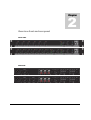
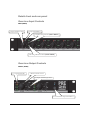
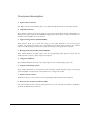
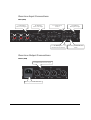
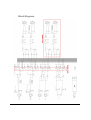
PRE16/26 AUDAC PROFESSIONAL AUDIO EQUIPMENT PRE16/26 6 Channel Pre-Amplifier – Single/Double Output Zone User Manual & Installation Guide AUDAC PROFESSIONAL AUDIO EQUIPMENT User Manual & Installation Guide ¤ AUDAC http://www.audac.eu [email protected] Index INTRODUCTION ..................................................................................................................................................................................................................... 3 ENVIRONMENT ...................................................................................................................................................................................................................... 4 SAFETY REQUIREMENTS ................................................................................................................................................................................................... 5 CAUTION – SERVICING ...................................................................................................................................................................................................... 5 OVERVIEW FRONT AND REAR PANEL .......................................................................................................................................................................... 6 FRONT .................................................................................................................................................................................................................................... 6 REAR ...................................................................................................................................................................................................................................... 6 OVERVIEW INPUT CONTROLS ......................................................................................................................................................................................... 7 INPUT (FRONT)..................................................................................................................................................................................................................... 7 OVERVIEW OUTPUT CONTROLS ..................................................................................................................................................................................... 7 OUTPUT ( FRONT ) ............................................................................................................................................................................................................... 7 FRONT PANEL DESCRIPTION ........................................................................................................................................................................................... 8 OVERVIEW INPUT CONNECTIONS .................................................................................................................................................................................. 9 INPUT (REAR) ....................................................................................................................................................................................................................... 9 OVERVIEW OUTPUT CONNECTIONS ............................................................................................................................................................................. 9 OUTPUT (REAR) ................................................................................................................................................................................................................... 9 REAR PANEL DESCRIPTION ............................................................................................................................................................................................ 10 CONNECTIONS AND CONNECTORS .............................................................................................................................................................................. 11 GETTING STARTED ............................................................................................................................................................................................................ 12 BLOCK DIAGRAM ............................................................................................................................................................................................................... 13 ADDITIONAL INFORMATION .......................................................................................................................................................................................... 14 TECHNICAL SPECIFICATIONS ....................................................................................................................................................................................... 14 PERSONAL NOTES............................................................................................................................................................................................................... 15 2 Introduction This section briefly describes the possibilities of the PRE16/26 Preamplifier. T he PRE16/26 Preamplifier was developed as an easy to use, flexible solution for multifunctional use. During the development of the PRE16/26, the AUDAC-engineers wanted to achieve four goals: - Delivering a flexible audio solution to control multiple functions - Easy to use - Excellent sound quality - Modern and advanced design The Audac PRE16/26 stereo preamplifiers are designed to be used in combination with the Audac D, T, Q and CPA Series Amplifiers, but can also be used for various other applications. It has 2 balanced XLR microphone inputs which are both equipped with a gain control, a 3-band tone control, phantom power and a talk over function. Channel 1 is constructed as a balanced stereo line input channel, fitted with 2 balanced XLR connectors, a stereo/mono switch and a gain control. Channels 2, 3 and 4 are constructed as unbalanced stereo line input channels, each fitted with 2 RCA/Cinch connectors and a gain control. The output section features 2 balanced XLR connectors and a stereo/mono switch for every output zone. The PRE16/26 can be used in commercial applications such as restaurants, hotels, shops, warehouses, professional offices, public buildings, and many more. 3 1 Chapter Environment Do not place this unit in an enclosed environment such as a bookshelf or closet. Ensure that there is adequate ventilation to cool the unit. Do not place the unit in environments which contain high levels of dust, heat, moisture or vibration. Do not use the unit near water or other liquids. Make sure no water or other liquids can be spilled, dripped or splashed on the unit. This unit was developed for indoor use only. Do not use it outdoors. Do not place objects on top of the unit. Place the unit on a stable base or mount it in a stable 19” rack. 4 Safety Requirements Always handle the unit with care. Only use a grounded socket outlet and a power cord with grounding plug to plug in the unit. This unit is not a toy. It should not be operated by children. Do not stick objects through the openings. Do not open the unit (risk for electrical shock). * CAUTION – SERVICING This unit contains no user serviceable parts. Refer all servicing to qualified service personnel. Do not perform any servicing unless you are qualified to do so. Note This product conforms to the following European Standards: EN 50081-1: 1992, EN 50082-1: 1992, EN 60065: 19 5 2 Chapter Overview front and rear panel FRONT PANEL REAR PANEL 6 Details front and rear panel Overview Input Controls INPUT (FRONT) 1. Input Volume Control 2. Clip LED indicator 3. Signal routing buttons (ONLY PRE26) 4. Routing indication LED’s (ONLY PRE26) Overview Output Controls OUTPUT ( FRONT ) 5. 6 segment LED bar 7. Master volume control 6. Output channel EQ control 8. Power button and power indicator 7 Front panel description 1. Input Volume Control: The Input Volume Control knobs allow you to adjust the individual level for each input channel. 2. Clip LED indicator: These indicator LED’s warn against clipping on the input signal. When the clip LED indicator is flickering, the input signal level is 3dB below clipping level and the gain control potentiometer on the back of the amplifier has to be reduced. 3. Signal routing buttons (ONLY PRE26): These buttons allow you to select the routing of every input channel to one or both output channels. By pressing this button, the corresponding input signal will be routed to the selected output zone. By pressing the same button again, the routing of the signal will be repealed. 4. Routing indication LED’s (ONLY PRE26): These LED’s indicate to which output zones the corresponding input signal is routed. The Z1 LED represents Output 1, and Z2 represents Output 2. 5. 6 Segment LED bar: This LED bar indicates the level of the output signal for the corresponding output zone. 6. Output channel EQ control: Every output channel has a two band tone control whereby specific frequency ranges of the signal can be amplified or attenuated. It can be adjusted over a range of ± 15 dB. 7. Master volume control: With this knob, the overall volume of the corresponding output channel can be adjusted. 8. Power button and power indicator LED: The power switch has to be used for turning the device on/off. A blue power indicator LED lights up when the PRE16/26 is turned on. 8 Overview Input Connections INPUT (BACK) 9. Unbalanced Stereo Line Inputs 10. Balanced Stereo Line Input 11. 3 Band Tone Control 13. Microphone Phantom Power Switch Overview Output Connections OUTPUT (BACK) 15. Balanced Stereo Line output 16. AC power inlet with fuse 9 12. Balanced Microphone input 14. Microphone Talk over switch Rear panel description 9. Unbalanced stereo line inputs: These unbalanced line level inputs can be connected to equipment with unbalanced line level outputs. A gain control potentiometer is provided to control the level of the input signal. There are three stereo unbalanced line inputs available on the PRE16/26. 10. Balanced stereo line input: The balanced stereo line input allows connecting a music source with balanced line outputs. A gain control potentiometer is provided to control the level of the input signal and a mono/stereo switch allows to select the output mode. When switched to mono, the stereo signals are mixed to mono and are available on both Left and Right output channels. 11. 3 Band tone control: Every microphone input channel has a separate three band tone control, whereby specific frequency ranges of the signal can be amplified or attenuated. It can be adjusted over a range of ± 15 dB. 12. Balanced microphone input: There are two balanced microphone inputs available 13. Microphone phantom power switch: If a microphone requires phantom power, the phantom power switch of the corresponding Mic channel can be switched ON. This applies +15 V DC phantom power to the microphone. 14. Microphone talk over switch: When the talk over switch is turned ON, all other connected music sources will be suppressed when a signal is present at the corresponding Mic channel. This function is mainly used for paging purposes. 15. Balanced stereo line output: The output zone(s) have balanced stereo XLR output terminals. The main amplifier can be connected to these output terminal. 16. AC power inlet with fuse: The mains power supply (110~240V AC / 50~60 Hz) has to be applied to this AC power inlet. The connection is made by an IEC power connector and is fitted with a fuse. When replacing the fuse, make sure that the value of the replacement fuse matches the value of the original fuse (500 mA / 250V). 10 3 Chapter Connections and Connectors The in- and output connections of AUDAC audio equipment are performed corresponding to international wiring standards for professional audio equipment. Cinch (RCA): tip = signal (left or right) ring = ground XLR: 1 = ground / shield 2 = +sig 3 = -sig XLR female: XLR male: 6.3mm (1/4”) balanced jack plug: tip = +sig ring = -sig sleeve = ground / shield 6.3mm (1/4”) unbalanced jack plug: tip = signal sleeve = ground / shield 11 4 Chapter Getting Started The PRE16/26 Preamplifier can be switched on by pressing the power button on the front panel. The blue ‹ ON › LED will light up if the device is powered-up. On the front panel, every channel has a Clip LED indicator to control the input levels. Each input channel also features 2 buttons and a series of green indication LED’s to control the routing of the input signal (Only PRE26). For the output section, every zone has its own 6 segment LED bar, master volume control knob and 2 band control knobs to control the output signal. The volume of the input signals can be controlled by turning the volume knobs of the input signals on the front panel of the PRE16/26. The master volume knob and the 2 band tone control knobs allow you to adjust the volume, bass and treble of the output signal. A VU-bar indicates the signal level of the output signal. 12 Block Diagram 13 5 Chapter Additional Information Technical specifications Frequency response THD+N Residual Noise Signal to noise ratio Crosstalk Tone Control 20 Hz – 20 kHz < 0,1% <-75 dB > 90 dB <-75 dB ±15 dB Mic 1 - 2: 1,0 mV Ch 1: 200 mV Ch 2 - 4: 200 mV Mic 1-2: 600 Ohm balanced XLR Ch 1: 2 x 600 Ohm balanced XLR Ch 2-4: 47kOhm unbalanced RCA/Cinch 1,2 V 2 x 600 Ohm balanced XLR (PRE16) 4 x 600 Ohm balanced XLR (PRE26) 15V DC ± 3V 110~240V AC / 50~60 Hz 12 Watt Steel 19” Rack 482 x 325 x 44 mm 1 HE Black Input sensitivity Input impedance Output level Output impedance Phantom power Power supply Power Consumption Construction Mounting Dimensions (W x H x D) Unit Height Color 14 Personal notes 15