Download Rotaphor VI user manual
Transcript
®
Rotaphor System 6.0
Instruction Manual
Model
®
Ord. No.
Rotaphor System 6.0, 230V
Rotaphor® System 6.0, 110V
Rotaphor® System 6.0, 230V
021-100
021-190
021-200
Please read these instructions carefully before using this
apparatus!
Rudolf-Wissell-Str. 30
D-37079 Göttingen
Tel.: +49 551-50686-0
Fax: +49 551-50686-66
email: [email protected]
Internet: http://www.biometra.com
Service Department
Rudolf-Wissell-Strasse 14-16
D-37079 Göttingen
Tel.: +49 551-50881-10/12
Fax: +49 551-50881-11
email: [email protected]
1
2
3
4
5
2
Introduction......................................................................................................................... 4
1.1
Field of applications ....................................................................................................... 4
1.2
Special features ............................................................................................................. 4
1.2.1 Rotating Field Electrophoresis (ROFE) ..................................................................... 4
1.2.2 Easy to program, easy to run..................................................................................... 4
1.2.3 Integrated buffer circulation ....................................................................................... 4
1.3
Technical specifications................................................................................................. 4
1.3.1 Electrophoresis chamber ........................................................................................... 4
1.3.2 Gel tray ...................................................................................................................... 4
1.3.3 Control unit ................................................................................................................ 5
1.3.4 Rotaphor 6.0 Software............................................................................................... 5
1.3.5 Power Supply............................................................................................................. 5
Safety and Warning Notices .............................................................................................. 6
2.1
Definition of Symbols ..................................................................................................... 6
2.2
General Safety Instructions ........................................................................................... 6
Installation........................................................................................................................... 8
3.1
Content of delivery......................................................................................................... 8
3.1.1 Electrophoresis chamber ........................................................................................... 8
3.1.2 Gel casting frame....................................................................................................... 8
3.1.3 Computer ................................................................................................................... 8
3.1.4 Power supply ............................................................................................................. 8
3.1.5 Block former............................................................................................................... 8
3.2
Unpack and check ......................................................................................................... 8
3.3
Installation conditions .................................................................................................... 9
3.4
Setup of the thermostatic circulator ............................................................................... 9
3.5
Setup of the computer ................................................................................................... 9
3.6
Setup of the power supply ............................................................................................. 9
3.7
Final Settings ............................................................................................................... 10
Experimental Considerations.......................................................................................... 11
4.1
Introduction.................................................................................................................. 11
4.2
Software ...................................................................................................................... 11
4.2.1 Login-Screen ........................................................................................................... 11
4.2.2 Main screen ............................................................................................................. 12
4.2.3 Parameter editor ...................................................................................................... 13
4.2.4 Main screen during the run ...................................................................................... 15
4.3
Pre-set standard parameter lists.................................................................................. 17
®
4.4
Conventional gel electrophoresis with the Rotaphor System .................................... 17
4.5
Consequences of parameter modifications ................................................................. 17
4.5.1 Angles between 91° and 160° ................................................................................. 19
Materials and methods..................................................................................................... 21
5.1.1 Reagents ................................................................................................................. 21
5.2
Buffers and solution..................................................................................................... 21
5.2.1 Stock solution of TBE running buffer ....................................................................... 21
5.2.2 Stock solution of Loenning running buffer ............................................................... 21
5.2.3 TNE buffer ............................................................................................................... 22
5.2.4 NDSK buffer............................................................................................................. 22
5.2.5 TE buffer .................................................................................................................. 22
5.2.6 TAE buffer (1x) ........................................................................................................ 22
5.2.7 TBE buffer (0.5x) ..................................................................................................... 22
Instruction Manual Rotaphor
5.2.8 EC lysis buffer.......................................................................................................... 22
5.2.9 Zymolase solution.................................................................................................... 22
5.2.10
PMSF solution ..................................................................................................... 23
6
Sample Preparation.......................................................................................................... 24
6.1
Preparation of agarose plugs....................................................................................... 24
6.1.1 S. cerevisiae sample preparation ............................................................................ 24
6.1.2 E. coli sample preparation ....................................................................................... 25
6.1.3 Mammalian cells sample preparation ...................................................................... 26
6.1.4 Restriction enzyme treatment of agarose plugs ...................................................... 26
7
Operating........................................................................................................................... 28
7.1
Equipment ................................................................................................................... 28
7.2
Setting up the electrophoresis chamber ...................................................................... 28
7.3
Precautions.................................................................................................................. 28
7.3.1 Voltage..................................................................................................................... 28
7.3.2 Buffer concentration................................................................................................. 28
7.3.3 General precautions ................................................................................................ 28
7.4
Preparation of agarose gels......................................................................................... 29
8
Maintenance...................................................................................................................... 33
9
Service............................................................................................................................... 34
9.1
Instructions for return shipment ................................................................................... 34
10 Equipment Decontamination Certificate ........................................................................ 35
11 Note for the disposal of electric / electronic waste....................................................... 37
12 Warranty ............................................................................................................................ 38
13 Glossary ............................................................................................................................ 39
14 Trouble Shooting.............................................................................................................. 40
14.1 Rotaphor does not function ......................................................................................... 40
14.2 Experimental problems ................................................................................................ 41
1 Introduction
1.1
Field of applications
The Rotaphor® System is meant to be used for the separation of very large DNA molecules in
agarose gels by pulsed field electrophoresis (PFGE).
1.2
Special features
1.2.1 Rotating Field Electrophoresis (ROFE)
In contrast to conventional PFGE instruments with fixed electrodes the patented Rotaphor®
system features free rotating electrodes. Thus any angle can be set for the electric field.
Changing field angles over the time are achieved by the precise movement of the rotor. This
feature is of special importance for the separation of very large DNA molecules.
1.2.2 Easy to program, easy to run
The Rotaphor® Version 6.0 provides a convenient computer software for programming new
experiments and electrophoresis control. Seventeen pre-set programs are available for various
separation ranges and are an ideal starting point for new experiments. For each protocol a real
gel picture is shown in the software, individual pictures for custom protocols can be uploaded.
1.2.3 Integrated buffer circulation
The Rotaphor® system features an internal pump for efficient buffer circulation. Buffer flow from
an external refrigerated circulator and internal buffer flow are completely separated. An
integrated thermostat relay precisely monitors the buffer temperature and triggers if necessary
the cooling circuit.
1.3
Technical specifications
1.3.1
•
•
•
•
•
•
•
Electrophoresis chamber
Freely rotating electrode rotor with 14 platinum electrodes (160° max angle)
Integrated buffer circulation pump
Internal cooling circuit for connection of an external thermostat
Temperature sensor
2.4 l buffer volume
Acrylic glass safety lid (automatic shut off when lid is lifted)
Dimensions 35 cm x 47cm x 25cm (W x D x H)
1.3.2
•
•
•
•
•
•
Gel tray
Adjustable feet for horizontal levelling
20 x 20 cm gel format
18 cm separation distance
18 teeth comb, 2.0 mm (optional 40 teeth)
Gel casting frame
Moulding form for 20 agarose embedded samples
4
Instruction Manual Rotaphor
1.3.3
•
•
•
Control unit
Up to date Personal Computer with Windows™ operating system
Control interface for Rotaphor® electrophoresis chamber
Installed Rotaphor® 6.0 control software
1.3.4
•
•
•
•
•
•
•
•
•
•
•
•
•
•
•
Rotaphor 6.0 Software
17 optimized programs for separation of samples from 100 kb up to 6 Mb
Up to 11 programs can be combined and run subsequently
8 pre-installed combined program lists
Easy creation of new programs (angle, Voltage, Pulse length)
Maximum program length 500 hours
Programs can be linked to create complex separation pattern
Program in- or decremental field vectors (linear or logarithmic, 0° or 95°-160°)
Program in- or decremental pulse length (1 – 10.000 s)
Program voltage for electrophoresis 30-225 Volt (1 – 8,5 V / cm)
Precise control of buffer temperature (5 – 22 °C)
For each program a real gel picture can be loaded / displayed
Convenient user administration
Comprehensive online help
German or English language
Printed user manual
1.3.5
•
•
•
•
•
Power Supply
Rotaphor® 6.0 interface
Voltage: 0 – 300 V
Current: 0 – 450 mA
Dimensions: 5.2 cm x 22.2 cm x 20.2 cm (H x W x D)
Weight 1.7 kg
2 Safety and Warning Notices
2.1 Definition of Symbols
Symbol
Definition
Caution! Refer to instruction manual!
Danger! High voltage!
Fragile!
2.2 General Safety Instructions
Please read this manual carefully before starting operation of the Rotaphor® System.
•
General safety precautions for laboratory work must be observed when working with the
Rotaphor® System.
•
The Rotaphor® System does not produce a sound power level that could be hazardous for
the user.
The Rotaphor® System contains no user serviceable parts. Do not
open the instruments housing. Service and repair may only be
carried out by the Biometra Service department or otherwise
qualified technical personal.
Do not use the instrument when damages of the housing, cable or
other parts are visible.
Unplug the power cable before you open the Rotaphor® System.
Danger of electric shock!
Make sure that the appliance connector and the plug of the supply
cord are accessible, so you can separate the instrument from the
mains.
Connect the Rotaphor® System to a grounded socket.
Appropriate safety regulations must be observed when working with
infectious, pathogenic or radioactive material. Ask the responsible
local safety inspector for details.
The Rotaphor® System must not be used with explosive, flammable
or volatile liquids.
6
Instruction Manual Rotaphor
This instrument is designed and certified to meet EN 61010-1 safety
standards. It should not be modified or altered in any way. Alteration
of this instrument will void the warranty, void the EN61010-1
certification, and create a potential safety hazard.
Place the Rotaphor® System on a stable, non flammable surface in a
dry, safe environment.
Do not use alcohol (e.g. methanol, ethanol), organic solvents or
abrasives to clean the instrument.
For transports always use the original Biometra box.
3 Installation
3.1 Content of delivery
3.1.1
•
•
•
•
3.1.2
•
•
•
Electrophoresis chamber
Lower part with data and power cable
Safety lid with Rotor V2.1
Gel support tray
4 corner insulators
Note: Each Rotaphor® System is checked individually and therefore faint scratches on the
gel support tray may occur during this testing.
Gel casting frame
20 x 20 cm frame
Comb with 18 wells
Four locating screws
3.1.3
•
Computer
Computer with pre-installed Windows™ operating system, Rotorgene® software and
controller card (without monitor)
• Power cord
• Manuals of the computer components
• Windows™ licence
• Keyboard
• Mouse
Optional:
• Speakers
3.1.4
•
•
•
3.1.5
Power supply
Electrode power cable
Power cord
Connection cable to the interface card
Block former
- Insert mould with 20 holes
- block remover
3.2 Unpack and check
Unpack and carefully examine the instrument. Remove all adhesive tape. Report any damage to
Biometra. Do not attempt to operate this device if physical damage is present.
Please keep the original packing material for return shipment in case of service issues
8
Instruction Manual Rotaphor
3.3 Installation conditions
•
Place the Rotaphor® System on a stable surface in a dry, safe environment.
Placing the lid on an uneven surface or closing the lid with the gel casting
frame mounted, can damage the electrodes!
3.4
Setup of the thermostatic circulator
The thermostatic circulator can be ordered separately and is not part of the Rotaphor® System.
The applied electrical field produces heat of 30 W that needs to be removed from the
electrophoresis chamber. We recommend a thermostatic circulator to cool the Rotaphor®
System electrophoresis chamber efficiently during the run. Ideally it should contain at least 5 l of
methanol/water or glycerine/water coolant.
Connect the silicon tubing (best with temperature isolation) to the inlet and outlet of the
electrophoresis chamber and secure the connections with hose clamps. Connect the other ends
of the inlet and outlet of the thermostatic circulator.
IMPORTANT: Connect the outlet of the thermostatic circulator to the inlet of the electrophoresis
chamber and the outlet of the electrophoresis chamber to the inlet of the thermostatic circulator.
3.5 Setup of the computer
Connect the following cables to the sockets at the back of the computer:
• Keyboard connector (encoded violet)
• Mouse connector (encoded light green)
• Monitor connector (VGA connector – it fits to the graphics card, encoded blue)
• Cable of the electrophoresis chamber (fits to the controller card installed at the computer)
• Data cable of the electrode power supply (fits to the controller card installed at the
computer)
• Optional: Loudspeaker connector (encoded green)
Connectors on most cables ensure error–proof fitting. Secure connectors with screws by
fastening the screws.
3.6 Setup of the power supply
Connect the power supply to the sockets at the back of the electrophoresis chamber using the
electrode power cable. The red banana plug corresponds to the anode (+), the black to the
cathode (-). Theoretically, any power supply providing 250V, 400mA is sufficient for virtually all
possible applications, but we do explicitly not recommend it, since only the electrode power
supply from Biometra has a suitable interface. This interface enables the computer to control the
field strength automatically and to switch of electrode voltage if no electrophoresis is running.
3.7 Final Settings
Use the levelling feet to maintain a horizontal position of the electrophoresis chamber. Because
it is very important for optimal results, measure the horizontal position of the electrophoresis
chamber at the top of the safety lid at the 3 possible sides with a large spirit level and correct the
position, if necessary, with the levelling feet.
Connect the power cords to the rear of the computer, the monitor and the power supply. Finally,
connect the power leads to a properly grounded wall socket.
10
Instruction Manual Rotaphor
4 Experimental Considerations
4.1 Introduction
The search for a theoretical basis regarding the separation of very large DNA by pulsed field gel
electrophoresis revealed that no simple theory describes the all the characteristics of this
method. We will therefore use a relatively simple model to define parameters for separations of
the desired size range. In all cases, the following parameters have to be considered:
•
Size of the nucleic acid molecules
•
Interval
•
Angle between the orientations of the electric field
•
Field strength
•
Temperature
•
Agarose concentration
•
Ionic strength of the electrophoresis buffer
•
Duration of electrophoresis
4.2 Software
The Rotaphor System® is controlled by the Rotaphor® Software. The software features a user
management and demands the user to login after program start. After login the software is
started that is divided into two main screens: In the parameter editor parameter lists are
programmed and in the main window the applied parameters and messages are shown.
4.2.1
Login-Screen
After starting the Rotaphor® Software at first a user account for login has to be selected (see
Figure 1). Select a user from the displayed list, enter the user specific password and press
“Select user account”.
Figure 1 Login-Screen
To create a new user account press “Create user account”. In the next screen (see Figure 2)
enter a user name, select a language and define a password (optional). Personal data will be
saved in the preset directory. Optionally an alternative path and directory can be set.
Figure 2 Create a user account
To cancel the creation of a new user account press “Do not create user account”.
4.2.2 Main screen
The Rotaphor® Software main screen displays all important parameters during the run (see
chapter 4.2.4). Additionally, the main screen features a menu to administrate the Rotaphor®
System:
Options
User Administration
Temperature Calibration
Rotor Speed
Logbook
Help
Exit
Help
About
12
Can be used to create new user accounts or to change
individual settings like password and language. All
changes have to be confirmed by “Save Changes”.
Before delivery the Rotaphor® System is calibrated
thoroughly. However, if the temperature sensor should
be misaligned a recalibration is possible. For this
purpose the buffer temperature in the electrophoresis
chamber has to be measured at room temperature and
the measured value to be entered in the field “°C”.
If necessary the rotor speed can be adjusted between 0
and 99%.
The logbook records all actions and messages during a
run. It is a useful tool for failure analysis.
Closes the Rotaphor® Software
Comprehensive help function for the Rotaphor®
Software
Provides information on the software version and serial
number
Instruction Manual Rotaphor
Figure 3 Rotaphor® Software main screen
4.2.3 Parameter editor
To access the parameter editor press button “Edit Parameter Lists” in the main window (see
Figure 6). In the parameter editor 9 preset lists for different sizes of fragments are available:
1
2
3
4
5
6
7
8
9
1kb-100kb 14h
2kb-200kb 18h
3kb-250kb 21h
1kb-450kb 23h
2kb-800kb 24h
3kb-1600kb 24h
20kb-2600kb 48h
0kb-5700kb 120h
0kb-5700kb 240h
Each preset parameter list has been tested thoroughly and for each list a gel picture is displayed
that gives an impression about the results that can be expected. In the “Comments” field useful
additional information on the used buffer type and concentration and the agarose concentration
is given. Please note that the preset parameter lists are marked by a © sign and cannot be
deleted.
Note: For those customers who use the instrument for the first time we strongly recommend to
start with a preset parameter list before programming individual parameter lists.
Figure 4 Rotaphor® Software parameter editor
To optimise the separation of samples it might be necessary to refine a parameter list and to
program an individual protocol.
• Press “New Parameter List”
• Enter a name for the new parameter list in the field “Name of List”.
• Enter parameters for
o Duration (h) [1-500 h]
o Temperature (°C) [1-25 °C]
o Interval (sec) [1-10000 sec]
o Angle (°) [0°, 90°, 91°-160°]
o Voltage (V) [1-255V]
• For the interval, angle and voltage two parameters each have to be set and the mode to
be selected. The mode defines the course with that the instrument changes between the
set parameters. If two identical values are programmed for a parameter the mode will be
set to “constant”. If two different values are programmed the mode can be set to “linear
to” or “logarithmic to” (see Figure 5 for the differences). For the angle 0° additionally the
mode “PFGE off” exists.
14
Instruction Manual Rotaphor
Constant
Linear to
Logarithmic to
Figure 5 Modes available to define the course between two parameter values
•
•
•
•
If necessary enter comments in the field “Comments”.
To save the parameter list press “Accept changes”
To delete a parameter list press “Delete Parameter List”
Tipp: For the separation of small fragments (25 kb or smaller) the checkbox beside
“Duration” has to be activated:
With activated checkbox the current is applied also during rotor movements. This
ensures a good separation of very small fragments.
To load a parameter list of another user use the drop down menu “Lists of other users/backups”.
Select the user from the drop down menu and then select one of the loaded parameter lists.
For each custom parameter list a gel image can be assigned. Press “Assign Image” and select a
*.jpg or *.gif file to be uploaded. The gel image is linked to the currently activated parameter list.
In this way a database of parameter lists and corresponding gel images can be created.
The Rotaphor® Software also allows to combine parameter lists. Combined parameter lists are
useful whenever parameters should undergo several changes during the run. The single lists are
run consecutively by the instrument. In the parameter editor 8 preset combined lists for different
sizes of fragments are available. As for the single parameter lists they are also marked by the ©
sign and cannot be deleted.
To start a run select a parameter list or combined parameter list and press “Use Selected List for
Experiment”. Them the parameter editor is closed and the main window is shown. In the main
window the name of the selected parameter list is displayed under the button “Start
Electrophoresis”.
4.2.4 Main screen during the run
After starting a parameter list currently applied values for different parameters like interval, angle
and voltage are displayed. The software additionally counts the remaining run time (duration),
the time to the next rotor movement (next move) and provides information when the
electrophoresis will be finished (probably finished at).
The software records the status of all system components and messages regarding the
electrophoresis by time and date in a message box. In the message box also failures are
displayed. In addition with the logbook function the recorded messages are an important tool to
monitor the electrophoresis and for failure analysis.
Figure 6 Main screen during the run
The main screen provides three checkboxes for user interaction:
Control
Temperature control on or off. The temperature
temperature set in the parameter list is shown in the field “Set
Temperature (°C)” and the measured buffer
temperature in big digits above. The Rotaphor®
System automatically controls the buffer
temperature in the electrophoresis chamber by a
valve. The control function for the buffer
temperature can be switched off.
Pump
Internal buffer pump on or off. For the application
of liquid samples the pump has to be switched
off. The pump can be switched on manually (10 15 min after sample application) or switches on
automatically after 30 min.
Alarm
Alarm on or off. The alarm function gives an
acoustic signal in case of a failure.
A running electrophoresis can be paused at any time. Press “Interrupt Electrophoresis” to pause
the run and “Continue electrophoresis” to continue a paused run.
16
Instruction Manual Rotaphor
4.3 Pre-set standard parameter lists
The controller software includes numerous parameter lists covering most of the separation
needs. After selection of such a parameter list, an image of a separation of different size
markers will be shown that was generated using the respective parameters. These images are
intended to provide a realistic idea of the inherent separation performances and should act as
guidelines for initial separation conditions for a given DNA size range. If you need to fine tune
the separation conditions, we recommend that you start with a standard list and apply subtle
changes.
Please note that an alteration of only one parameter mentioned above will lead to a different
behaviour of DNA molecules in the gel with obvious consequences for their separation. If, for
instance, the voltage is increased by 2 Volts at the separation of S. pombe, the upper bands
fade or become invisible (see below).
4.4 Conventional gel electrophoresis with the Rotaphor® System
It is also possible to run a conventional electrophoresis with the Rotaphor. In this case, place the
gel support tray (with gel and corner insulators) into the buffer filled electrophoresis chamber and
wait until buffer has reached the predetermined temperature. Stop buffer circulation by turning of
the pump by unchecking the box Pump in the main window. Otherwise the buffer circulation will
wash your samples out of the wells. Enter the DNA (in sample buffer e.g. 10% glycerine) directly
into the wells of the gel. Close the lid very carefully, choose for start and end angle 0° (if you
want to apply this electrophoresis as 2nd dimension after a PFGE, please enter 90° for start and
end angle. Please note that the DNA moves from right to left in this second dimension). Enter
also a suitable duration and field strength and start electrophoresis. Since inhomogeneous
temperatures impair the results, the buffer circulation pump will start after 30 minutes
automatically.
4.5 Consequences of parameter modifications
Using a simple theory developed by Southern and colleagues, the consequences of
modifications made to parameter lists shall be discussed. This theory explains relatively well the
observed changes of DNA mobility if applied only qualitatively and if parameters are not
changed dramatically.
Two DNA molecules are shown, a
large DNA (~300kb) and a small
one (~50kb). These move, driven
by the electrical filed, through the
gel pores.
After changing the field angle by
90° or less, the DNA molecules will
move into the new direction. After
direction change, the leading end is
still the leading end.
Since velocity of DNA molecules
with a size above 50 kb is virtually
identical, no separation of the small
and large molecules will be
observed.
.
18
Instruction Manual Rotaphor
4.5.1
Angles between 91° and 160°
Looking at the pulsed field gel
electrophoresis, the situation is identical
at the beginning.
However, the angle between the field
vectors is more obtuse at PFGE.
Consequently, the force in backwards
direction is larger that in forwards
direction. Therefore, the trailing end
becomes the leading end and the whole
molecule if forced through the pore
which harboured this end when the field
was last changed. Since the trailing end
of a short molecule is not as far behind
as the trailing end of a larger DNA
molecule, the shorter molecule has
moved further than the larger molecule.
The position difference Δ results in the
observed separation of the respective
molecules.
This simple theory allows the prediction
of the consequences of parameter
changes, which fit the observed
behaviour very closely, at least if only
subtle changes are applied.
.
1. Duration
The duration of an electrophoresis is directly proportional to the distance a given DNA
molecule moves during a run, if no exponential voltage ramps are used. The separation
distance Δ increases proportional to the travelling distance, and therefore also proportional
to the duration. In reality, it has to be taken into account that a gel has a limited size and
bands which have left the gel are lost.
2. Interval
According to the theory shown above, the separation distance Δ increases with the number
of pulses. Since separation takes place only, if the lagging ends of all molecules that should
be separated have left the pore of the pulse before, the product of interval (time) and field
strength (voltage) needs to be adequately high. Otherwise, the larger molecules are trapped
in a pore, do almost not move and are not separated. It might therefore be concluded that
increasing interval and/or voltage increases the upper border of the separation range. Since
in both cases the number of pulses per run is reduced (higher voltages result in shorter
duration), the separation distance between two given molecules is also reduced.
3. Angle
According to the above theory, the angle should be not relevant for the separation quality if it
is larger than 90°. Only the duration needed for the same travelling distance should increase
with the angle. This fits more or less the observed situation, but more obtuse angles result in
sharper bands. It therefore needs to be decided whether short runs or sharp bands are most
relevant.
4. Voltage
Most of the influence of the field strength has already been discussed together with the
interval, but there is an observation which needs to be mentioned: If the DNA molecules are
larger than 2000 kb a phenomenon called “trapping“ leads to impaired results. Trapping
means that a voltage dependent fraction of the molecules is “trapped” each pulse in the gel.
If huge amounts of such DNA are applied to the gel, these trapped molecules may be seen
after staining as smeary ladder. Consequently, the amount of DNA in the “real band” is
reduced every pulse resulting in complete disappearance of the “real band” if the voltage is
too high for the separation problem. Especially if the size of the molecules becomes > 4
mbp, the voltage needs to be reduced to very low values (~40V). This leads to very long
durations and limits therefore the upper size of DNA molecules that may be separated by
PFGE.
5. Temperature
The temperature has a relatively small influence on the separation. Only the duration needs
to be increased with lower temperatures. If the temperature is lowered from 13 to 8°C, the
molecules move about 30 % less down the gel in the same time. Since the non separated
molecules move also faster at high temperatures, the upper part of the gel is wasted at
elevated temperatures. Additionally, high temperatures lead to blurred bands.
20
Instruction Manual Rotaphor
5 Materials and methods
Please note that not all of the listed reagents and buffers needed for an experiment. Please read
carefully the instructions in chapter 6 to decide which reagents and buffers have to be prepared.
5.1.1
•
•
•
•
•
•
•
•
•
•
Reagents
0.05 M EDTA, pH 7.5
0.125 M EDTA, pH 7.5
ß-Mercaptoethanol
0.5 M EDTA, pH 9.5
PBS buffer
BSA, acetylated (if required for restriction enzyme)
Triton X-100, membrane research grade
Restriction enzyme and corresponding 10x reaction buffer
Standard (LE) or high gelling temperature (HGT) agarose for standard gels
LMP agarose for preparative gels
5.2 Buffers and solution
Please note that best electrophoresis results are usually obtained with 0.025 M TBE (pH 8.5)
running buffer.
5.2.1 Stock solution of TBE running buffer
To prepare 1 l stock solution (usually known as 10x TBE), dissolve the following substances in
900 ml deionized (or distilled) water:
• 108 g Tris
• 55 g Boric Acid
• 40 ml 0.5 M EDTA pH 9
Adjust volume to 1000 ml
IMPORTANT: Store this stock solution at 4°C and do not keep it for more than two weeks!
The electrophoresis buffer is obtained by diluting the stock solution 1:40 with distilled water
(0.025 x TBE - 60 ml / 2400 ml). Pour 2.4 l of this buffer into the electrophoresis chamber.
5.2.2 Stock solution of Loenning running buffer
To prepare 1 l stock solution, dissolve the following substances in 900 ml deionised (or distilled)
water:
• 44 g Tris
• 42 g NaH2PO4 * H2O
• 20 ml 0.5 M EDTA pH 7.5
Adjust volume to 1000 ml
Store this stock solution at room temperature.
Instruction Manual Rotaphor
21
The final electrophoresis buffer is obtained by diluting the stock solution 1:30 with distilled water
(80 ml / 2400 ml). Pour 2.4 l of this buffer into the electrophoresis chamber.
IMPORTANT: This buffer withstands only an electrophoresis duration of less than 30 hours but
small DNA fragments (20-100kb) resolve very well. The current with this buffer is very high.
Therefore do not apply voltages above 130V, otherwise the rotor electronics might be damaged
or the fuse will blow.
5.2.3
•
•
•
TNE buffer
10 mM Tris
200 mM NaCl
100 mM EDTA (pH 7.2)
5.2.4 NDSK buffer
• 0.5 M EDTA
• 1% (w/v) N-laurylsarcosine
• 1 mg ml-1 Proteinase K (pH 9.5)
Solution may need to be heated to 50 °C to dissolve components.
5.2.5
•
•
TE buffer
10 mM Tris
1 mM EDTA (pH 8.0)
5.2.6
•
•
TAE buffer (1x)
40 mM Tris-acetate
1 mM EDTA (pH 8.0)
5.2.7
•
•
TBE buffer (0.5x)
44.5 mM Tris-borate
1 mM EDTA (pH 8.3)
5.2.8
•
•
•
•
•
•
•
•
EC lysis buffer
6 mM Tris-HCl (pH 7.6)
1 M NaCl (w/v)
100 mM EDTA
0.5% (w/v) Brij-58 (polyoxyethylene 20 cetyl ester
0.2% (w/v) deoxycholate
0.5% (w/v) N-laurylsarcosine
1 mg ml-1 Lysozyme
20 µg ml-1 RNase.
5.2.9
•
Zymolase solution
Add Zymolyase 20-T to glycerol-phosphate buffer (10 mM sodium phosphate and 50%
(v/v) glycerol (pH 7.5)) at a concentration of 1 mg ml-1.
22
Instruction Manual Rotaphor
Store at -20 °C.
5.2.10 PMSF solution
• Prepare a 0.1 mM solution of PMSF (phenylmethanesulfonyl fluoride) in isopropyl
alcohol.
Store at -20 °C.
Instruction Manual Rotaphor
23
6 Sample Preparation
This protocol* is designed to provide a basic introduction to sample preparation and techniques
that are unique to PFGE. Sample preparation for PFGE is fundamentally different from standard
agarose electrophoresis. Mechanical shear forces are present in liquid-phase samples, and
genomic DNA molecules above 500 kb are mechanically unstable and will fragment easily if
stirred or pipetted. To prepare and preserve intact chromosomal molecules for electrophoretic
analysis, a solid-phase DNA preparation technique, termed agarose "plugs" is typically used.
This protocol provides a basic starting point for Escherichia coli, Saccharomyces cerevisiae and
mammalian cells. Following DNA isolation, chromosomal DNA is typically digested or
"fingerprinted" using restriction enzymes. Many protocols have been developed over the years
for restriction digestion of genomic DNA in agarose plugs. The average pore size in an agarose
matrix is typically quite large (100-200 nm), thus allowing diffusion of enzymes and cofactors.
However, to accelerate this process, agarose plugs are made smaller either during preparation
by making agarose "beads” or by mincing a large and fully prepared agarose plug into smaller
pieces (agarose "chops”). It has been shown that the process of mincing and forming chops
does not break DNA, and this procedure is included.
*
(adapted from Herschleb et al., Nature Protocols, Vol.2 No.3, 677-684, 2007)
6.1 Preparation of agarose plugs
Please note that the sample preparation will take 2-3 days (excluding culture growth).
1. Determine the shape and volume of the desired plugs. Ideally, the plugs should
correspond to the dimensions of the wells in the final agarose gel. When the agarose
blocks are prepared with the sample mould provided, they will match the size of teeth of
the comb delivered with the Rotaphor System. Before filling up the holes of the mould,
moisten the mould by immersing it into water (this avoids air bubbles at the corners). Dry
the surface and seal one side of the mould with water resistant adhesive tape.
Alternately, agarose plugs can be prepared by simply filling a small 1ml syringe (with the
tip cut off) or trough with the agarose:cell mixture and cutting the resulting brick into
slices that approximate the volume of the wells.
2. Obtain sample material from any desired source, including bacterial cultures, yeast
cultures, mammalian cultured cells, lymphocytes, frozen tissue, etc. A good starting point
for genomic DNA concentration is ~1-2 µg per plug, but this value can vary substantially
depending on the application of a particular PFGE experiment. Approximate cell counts
for 2 µg genomic DNA plugs are ~6 x 10⁷ cells per plug for S. cerevisiae DNA (genome
size ~12 Mb), ~2 x 10⁸ cells per plug for E. coli DNA (genome size ~5 Mb) and ~3 x 10⁵
cells per plug for mammalian DNA (genome size ~3,000 Mb).
3. Separate the cells from storage or growth media and wash to remove debris and
prematurely lysed cells. Follow the following instructions for sample preparation for S.
cerevisiae, E. coli or mammalian cells.
6.1.1
a)
b)
24
S. cerevisiae sample preparation
Pellet cells by centrifuging at 1,000g for 15 min at 4 °C.
Discard the supernatant and wash the cells twice in 0.05 M EDTA (pH 7.5) (spin down
the cells at 1,000g for 15 min at 4 °C after each wash), keeping the samples on ice
during washes.
Instruction Manual Rotaphor
c)
d)
e)
f)
g)
h)
i)
j)
6.1.2
a)
b)
c)
d)
e)
f)
g)
h)
Count the cells using any reliable method. CRITICAL STEP When resuspending pellets
after the final wash and/or count, keep in mind that this solution will be diluted 1:1 into
agarose. Calculate cell concentration and resuspension volume accordingly.
Heat a 1.2% solution of LMP agarose in 0.125 M EDTA (pH 7.5) and equilibrate to ~4250 °C in a waterbath. This solution can be held until ready for use.
Mix the cells and agarose together. Mix the cells with an equal amount of agarose. Also
add 15.5 µl of Zymolyase solution per ml of agarose:cell suspension. CRITICAL STEP
Warm the cell suspension briefly in a 37 °C waterbath before mixing with agarose. When
mixing, take care to pipette thoroughly but slowly, to avoid damaging the cells and
shearing the DNA. Keep the agarose:cell suspension in a beaker of warm water on the
benchtop to avoid premature gelation.
Pipette the agarose:cell suspension into a casting mould, taking care to avoid air
bubbles. Allow the moulds to set at 4 °C until the agarose has gelled.
After solidification of the low melting point agarose plugs (~15 min), remove the tape and
push the blocks out of the mould by using the plexiglas remover provided with the
apparatus. For convenience, cut the blocks with a scalpel into two identical parts and
transfer them into a container filled with NDS-buffer. If the agarose:cell suspension was
poured in a syringe as a brick, slice the brick into appropriate pieces.
Incubate the plugs in 0.5 M EDTA containing 7.5% ß-mercaptoethanol overnight at 37 °C
to create spheroplasts, disrupt membranes and digest other cellular debris. Ideally, use a
50 ml conical tube and at least 2x the volume of the plugs of buffer. CRITICAL STEP In
general, more buffer is better, but some reagents can be costly.
Drain the buffer from the tube and replace with NDSK.
Incubate overnight in NDSK at 50 °C.
E. coli sample preparation
Pellet cells by centrifuging at 2,000g for 15 min at 4 °C.
Discard the supernatant and wash the cells in TNE buffer twice (spin down the cells at
2,000g for 15 min at 4 °C after each wash), keeping the samples on ice during washes.
Quantitate the cells using any reliable method. CRITICAL STEP When resuspending
pellets after the final wash and/or count, keep in mind that this solution will be diluted 1:1
into agarose. Calculate cell concentration and resuspension volume accordingly.
Heat a 1.2% solution of LMP agarose in dH20 and equilibrate to ~42-50 °C in a
waterbath. This solution can be held until ready for use.
Mix the cells and agarose together. Mix the cells with an equal amount of agarose.
CRITlCAL STEP Warm the cell suspension briefly in a 37 °C waterbath before mixing
with agarose. When mixing, take care to pipette thoroughly but slowly, to avoid damaging
the cells and shearing the DNA. Keep the agarose:cell suspension in a beaker of warm
water on the benchtop to avoid premature gelation.
Pipette the agarose:cell suspension into a casting mould, taking care to avoid air
bubbles. Allow the moulds to set at 4 °C until the agarose has gelled.
After solidification of the low melting point agarose plugs (~15 min), remove the tape and
push the blocks out of the mould by using the plexiglas remover provided with the
apparatus. For convenience, cut the blocks with a scalpel into two identical parts and
transfer them into a container filled with NDS-buffer. If the agarose:cell suspension was
poured in a syringe as a brick, slice the brick into appropriate pieces.
Incubate the plugs in EC Lysis buffer overnight at 37 °C to create spheroplasts, disrupt
membranes and digest other cellular debris. Ideally, use a 50 ml conical tube and at least
2x the volume of the plugs of buffer. CRITICAL STEP In general, more buffer is better,
but some reagents can be costly.
Instruction Manual Rotaphor
25
i)
j)
6.1.3
a)
b)
c)
d)
e)
f)
g)
h)
Drain the buffer from the tube and replace with NDSK.
Incubate an additional two nights in NDSK at 50 °C.
Mammalian cells sample preparation
Pellet cells by centrifuging at 1,000g for 15 min at 4 °C. CRITICAL STEP Use a swinging
bucket rotor to prevent premature lysis.
Discard the supernatant and wash the cells in 1 x PBS twice (spin down the cells at
1,000g for 15 minutes at 4 °C after each wash), keeping the samples on ice during
washes.
Count the cells using any reliable method. CRITICAL STEP When resuspending pellets
after the final wash and/or count, keep in mind that this solution will be diluted 1:1 into
agarose. Calculate cell concentration and resuspension volume accordingly.
Heat a 1.2% solution of LMP agarose in 1 x PBS and equilibrate to ~42-50 °C in a
waterbath. This solution can be held until ready for use.
Mix the cells and agarose together. Mix the cells with an equal amount of agarose.
CRITICAL STEP Warm the cell suspension briefly in a 37 °C waterbath before mixing
with agarose. When mixing, take care to pipette thoroughly but slowly, to avoid damaging
the cells and shearing the DNA. Keep the agarose:cell suspension in a beaker of warm
water on the benchtop to avoid premature gelation.
Pipette the agarose:cell suspension into a casting mould, taking care to avoid air
bubbles. Allow the moulds to set at 4 °C until the agarose has gelled.
After solidification of the low melting point agarose plugs (~15 min), remove the tape and
push the blocks out of the mould by using the plexiglas remover provided with the
apparatus. For convenience, cut the blocks with a scalpel into two identical parts and
transfer them into a container filled with NDS-buffer. If the agarose:cell suspension was
poured in a syringe as a brick, slice the brick into appropriate pieces.
Incubate the plugs in NDSK for two nights at 50 °C to create spheroplasts, disrupt
membranes and digest other cellular debris. Ideally, use a 50 ml conical tube and at least
2x the volume of the plugs of buffer. CRITICAL STEP In general, more buffer is better,
but some reagents can be costly.
Store agarose plugs from any cell type in either NDSK buffer or 0.5 M EDTA (pH 9.5). If kept
at 4 °C, the plugs and chromosomal DNA will remain intact for years without any appreciable
degradation.
6.1.4 Restriction enzyme treatment of agarose plugs
Please note that the enzyme treatment will take 3 days.
4. Place the plugs in TE containing 0.01 mM PMSF (use several milliliters of solution per
plug). Incubate overnight at room temperature (20-25 °C), with gentle shaking.
5. Dialyze the plugs into a larger volume of TE (place plugs into a sterile 50 ml conical tube
filled with chilled buffer). Gently shake or rock the plugs at 4 °C and make several buffer
changes over the course of at least 24 h.
6. Prepare agarose "chops" by mincing a plug into smaller (~0.5-1 mm) pieces using a
sterile glass coverslip.
7. Prepare digestion mixture, total volume 200 µl, by combining 50 U of restriction enzyme,
20 µl of appropriate 10x restriction buffer, BSA (if required, add acetylated BSA at a
concentration recommended for the particular restriction enzyme; as many BSA
preparations are contaminated with nucleases, check using restriction buffer and test
DNA), 0.02% Triton X-100, agarose chops and sterile water to make up the volume.
26
Instruction Manual Rotaphor
Gently shake the plug at the recommended temperature overnight. CRITICAL STEP
Proper controls must be performed-all components of the digestion mixture (including the
chops themselves) must be checked for the presence of endogenous nuclease activity.
This can be achieved by setting up mock digestions with chopped plugs and restriction
buffer. Each additional reaction component can be added to a separate sample and
incubated at proper temperature for a few hours. Running PFGE on these samples will
reveal nuclease activity as smeared bands, or a smear of high-molecular-weight DNA
entering the gel matrix. Commercially purchased acetylated BSA occasionally contains
nuclease.
8. To stop the reactions, remove the digestion mixture and replace with ~1 ml NDSK.
Shake on ice for 2 h.
Store reaction products indefinitely in either NDSK buffer or 0.5 M EDTA (pH 9.5) at 4 °C, or
proceed with electrophoresis. CRITICAL STEP Digestions in agarose are typically robust.
Problems are usually traced to inhibitors and contaminants indicative of a specific lot of agarose.
Reaction conditions and times should be empirically determined. However, overnight digestion
with clean reagents typically produces good results. Other sources of agarose may also be
tested to boost restriction enzyme activity.
Instruction Manual Rotaphor
27
7 Operating
7.1 Equipment
•
•
•
•
Rotaphor System 6.0
Thermostatic circulator or suitable other cooling option
Sample mould (delivered with the Rotaphor System 6.0)
Gel casting tray and comb (delivered with the Rotaphor System 6.0)
7.2 Setting up the electrophoresis chamber
Open the electrophoresis chamber and take out the gel support tray. Pour 2.4 l of the selected
buffer into the electrophoresis chamber and switch on the computer if not already done. Start the
thermostatic circulator and allow the apparatus to cool to the desired temperature as displayed
in the main window. The optimum temperature range for most applications is 10°C to 15° C (see
below).
IMPORTANT: Do not use more than 2.4 l of electrophoresis buffer!
7.3 Precautions
There are some rules to be born in mind whenever using the Rotaphor® System.
7.3.1 Voltage
The Rotaphor® System is able to withstand a maximum voltage of 255 Volts. Voltages higher
than this will activate the fuse at the back of the controller and thereby disconnect the electrodes
from voltage. In addition, it is possible to damage the Rotaphor® System by applying voltages
higher than 255 V.
IMPORTANT: Never apply voltages higher than 255 V to the Rotaphor® System!
7.3.2 Buffer concentration
The Rotaphor® System is designed to work with the buffer concentrations described above.
Working with buffer concentrations higher than this, leads to a high current. Consequently, the
electronics generates a considerable amount of heat, especially at high voltages, which may not
be carried off properly. At 80°C, a fuse inside the rotor, or the fuse at the back of the controller
will disconnect the rotor from the electricity.
IMPORTANT: Never apply buffer concentrations that lead to a power consumption above 40 W!
7.3.3 General precautions
Some ions, e.g. chloride, will lead to corrosion or other structural changes of the platinum
electrodes. These ions are a normal component of tap water.
IMPORTANT: Use only deionized or double distilled water and chemicals of analytical grade.
Check quality of water and chemicals when electrodes do not shine metallically after a run.
The electronics of the Rotaphor® System is only water resistant, and not waterproof. Particular
care should be taken to minimize the periods of time the electronics are subjected to conditions
of high humidity (e.g. insufficient cooling of buffer during electrophoresis or storing the
28
Instruction Manual Rotaphor
electrophoresis chamber filled with buffer and lid closed) as this may, over a considerable period
of time, lead to corrosion of metallic components of the rotor electronics and chamber. The
Rotaphor® System will be destroyed in that way.
IMPORTANT: Please do not submerge the rotor electronics under water.
7.4 Preparation of agarose gels
Place the gel support tray on an even horizontal surface (check with spirit level), take away the
corner insulators and secure the gel casting frame to the tray with the four screws provided. To
prepare a 1% gel of 7 mm thickness, dissolve 3.0 g agarose in 300 ml of electrophoresis buffer.
Agarose gels from 0.5% to 1.5% can also be employed; the choice of concentration depends on
the length of the nucleic acid molecules which are to be separated and the band sharpness
desired. Heat the suspension to boiling in a microwave oven, ensuring that all agarose particles
are properly dissolved. Then, for convenience, seal the edges of the frame with agarose and let
cool down the rest of the suspension to about 50°C before pouring the gel. Then pour the gel,
and remove the remaining air bubbles from the 4 cylindrical holes and from the gel surface with
a pipette. At last position the comb. It fits the two cylindrical holes on top of the gel casting
frame.
Let the gel solidify for 45 min without moving it around! When the gel is set, carefully remove the
comb and cut the gel from the casting frame with a scalpel. Then remove the four screws and lift
the frame very carefully. Failures to take care at this point may result in the gel becoming
detached from the gel tray during electrophoresis. Avoid an uneven gel surface (see below).
Remove all loose agarose particles from the tray and close the holes of the 4 screws in the tray
at the lower side with water resistant adhesive tape, to avoid any possible distortion of the
electric field due to electricity flow through these holes.
Note: Pulsed field gel electrophoresis is not compatible with ethidium bromide in the gel during
the run. DNA becomes stiff and moves very badly if the dye is intercalated. Consequently, the
separation range is narrowed dramatically.
Instruction Manual Rotaphor
29
3.6 Loading the gel
To load the gel, cut the agarose plugs containing the sample to the desired size and insert them
into the wells using a metal spatula. Make sure that the plugs attach to the front wall (direction of
electrophoretic separation) of the well and finally “seal” the wells with some hot 1% agarose.
Now put the corner insulators over the distance pillars and press them down until they sit on the
gel support tray (see below). The corner insulators are held in place by a plastic pin which has to
be on the lower side. Adhesion pulls up the agarose solution at the casting frame and at the
comb. This causes an uneven gel surface. Especially after filling and capping the slots, the
30
Instruction Manual Rotaphor
buffer circulation above the gel is blocked by this agarose rampart. Therefore, cut away the
agarose rampart with a scalpel to allow free buffer circulation.
Mount the 4 corner insulators as shown in the right part of the figure. There should be no space
between gel support tray and the corner insulators.
3.7 Loading the electrophoresis chamber
After the buffer has reached the desired temperature, remove the safety lid. This action prevents
all current flow, to the electrodes as well as to the motor. Place the gel support tray with the gel
and the corner insulators into the electrophoresis chamber and lower it carefully until the tray
rests firmly on the inner edges of the tank. The sample wells have to be in the back of the
chamber near the electrical connectors. This will ensure the nucleic acids migrate in the correct
direction once the power supply is switched on and electrophoresis has commenced. The gel
should be covered by about 5 mm depth of buffer when the corner insulators are in place. Any
additional buffer required should be added at this point. Be sure, however, that the buffer level
does not reach the rotor electronics! Place the safety lid on the lower part of the electrophoresis
chamber and take care that all plugs fit into their respective sockets. Now the lid is safely
interlocked. Wait for 5 to 20 minutes until the temperature of the gel is approximately equal to
that of the electrophoresis buffer.
3.8 Start and termination of electrophoresis
After setting the parameters and pressing the “Start Electrophoresis” button, the anode and
cathode can easily be distinguished, at least when TBE is employed as electrophoresis buffer,
because more bubbles develop at the cathode than at the anode. DNA molecules move towards
the anode, therefore the anode should be the electrode at the front. The electronics of the
Rotaphor® System interrupts current flow when the polarity is wrong! The electrophoresis is
terminated automatically but it might be interrupted by pressing the “Interrupt Electrophoresis”
Instruction Manual Rotaphor
31
button at any time. Remove the safety lid and the corner insulators. Then lift the gel support tray
out of the electrophoresis chamber. Cut off the gel’s “feet” with a scalpel and slide it gently from
its support. Proceed as usual with staining, destaining, nicking, blotting and hybridization.
Note that special care has to be taken to prepare the gel for blotting when very long DNA
molecules have been separated. We have found that vacuum blotting gives an excellent
sharpness after transfer but the sensitivity of hybridization is better with capillary blotting.
After each electrophoresis experiment, the chamber should be emptied in the following way:
Insert one half of a tubing connector of the appropriate diameter into a long piece of silicone
tubing and press the other half into the outlet of the pump. The free end of the tubing should
hang into a large container standing on the floor. Switch off the pump at the controller, when the
tube is filled with buffer. Remove the buffer by gravity siphoning into the container. Moving
around the upper end of the tubing helps cleaning the chamber and the inlet of the pump from
agarose particulate matter. At the end of the draining procedure the instrument should be tilted
to remove the last small volumes of buffer.
In order to prepare the tray for the next gel, remove the agarose plugs from the 4 cylindrical
holes with a spatula or by vigorously blowing air into the holes. Check that the inlet of the buffer
circulation pump is free of all particulate matter. If the instrument is not to be used immediately,
let it air dry with the lid removed from the main chamber body. If the instrument is not to be used
for more than 1 week, pipette 0.5 ml glycerine into the pump inlet for pump maintenance.
32
Instruction Manual Rotaphor
8 Maintenance
The Rotaphor® electrophoresis chamber is designed to operate with aqueous solutions and not
with organic solvents! Do not run the buffer circulation pump without buffer in the electrophoresis
unit since the pump is not designed to run dry. The pump motor with the impeller is fitted to the
pump hose through a bayonet attachment and can be changed if necessary. It is not essential to
clean the electrodes or any other part of the lid routinely, but it is essential to empty the chamber
after each run. Do not close the Rotaphor® until chamber, tray and lid are dry. Very high humidity
(e.g. generated by buffers in the closed chamber at room temperature) leads to condensation on
the metallic parts of the electronics and can therefore lead to early age-hardening. If the
Rotaphor® electrophoresis chamber is not to be used for a long period of time, it should be
rinsed several times with tap water and finally once with deionised water. To dry, leave the
electrophoresis chamber upside down (without the lid) for a suitable period of time and then
pipet 0.5ml glycerine into the pump inlet, before storing it away.
Instruction Manual Rotaphor
33
9 Service
Should you have any problems with this unit, please contact our service department or your local
Biometra distributor:
Biometra GmbH
Service Department
Rudolf-Wissell-Straße 14 - 16
D-37079 Göttingen
Phone:++49 (0)5 51 50 68 6 - 10 or 12
Fax: ++49 (0)5 51 50 68 6 -11
e-mail: [email protected]
9.1
Instructions for return shipment
In case of an instrument failure that cannot be fixed by the procedures described in section
Fehler! Verweisquelle konnte nicht gefunden werden. please proceed as follows:
•
Return only defective devices. For technical problems which are not definitively recognisable
as device faults please contact the Technical Service Department at Biometra (Tel.: +49 55150881-10/12, Fax: +49 551-50881-11, e-mail: [email protected]).
•
Please contact our service department for providing a return authorization number (RAN).
This number has to be applied clearly visible to the outer box. Returns without the RAN will
be not be accepted!
•
Important: Carefully clean all parts of the instrument of biologically dangerous, chemical or
radioactive contaminants. If an instrument is contaminated, Biometra will be forced to refuse
to accept the device. The sender of the repair order will be held liable for possible losses
resulting from insufficient decontamination of the device.
•
Please prepare written confirmation that the device is free from biologically dangerous and
radioactive contaminants. The declaration of decontamination (see section 10) must be
attached to the outside of the packaging.
•
Use the original packing material. If not available, contact Biometra or your local distributor.
•
Label the outside of the box with “CAUTION! SENSITIVE ELECTRONIC INSTRUMENT!”
•
Please enclose a note which contains the following:
34
a)
Sender’s name and address,
b)
Name of a contact person for further inquiries with telephone number,
c)
Description of the fault, which also reveals during which procedures the fault occurred, if
possible
Instruction Manual Rotaphor
10 Equipment Decontamination Certificate
To enable us to comply with German law (i.e. §71 StrlSchV, §17 GefStoffV and §19 ChemG)
and to avoid exposure to hazardous materials during handling or repair, please complete this
form, prior to the equipment leaving your laboratory.
COMPANY / INSTITUTE
__________________________________________________
ADDRESS
______________________________________________________________
PHONE NO
_________________________
E-MAIL
______________________________________________________________
EQUIPMENT
FAX NO_________________________
Model
______________
Serial No
______________
______________
______________
______________
______________
______________
______________
If on loan / evaluation Start Date: __________________
Finish Date __________________
Hazardous materials used with this equipment:
__________________________________________________________________________
__________________________________________________________________________
__________________________________________________________________________
Method of cleaning / decontamination:
__________________________________________________________________________
__________________________________________________________________________
__________________________________________________________________________
The equipment has been cleaned and decontaminated:
NAME __________________________________ POSITION _______________________
(HEAD OF DIV./ DEP./ INSTITUTE / COMPANY)
SIGNED ________________________________ DATE ____________________________
Instruction Manual Rotaphor
35
PLEASE RETURN THIS FORM TO BIOMETRA GMBH OR YOUR LOCAL BIOMETRA
DISTRIBUTOR TOGETHER WITH THE EQUIPMENT.
PLEASE ATTACH THIS CERTIFICATE OUTSIDE THE PACKAGING. INSTRUMENTS
WITHOUT THIS CERTIFICATE ATTACHED WILL BE RETURNED TO SENDER.
General Information for Decontamination:
Please contact your responsible health & safety officer for details.
Use of radioactive substances:
Please contact your responsible person for details.
Use of genetically change organism or parts of those:
Please contact your responsible person for details.
36
Instruction Manual Rotaphor
11 Note for the disposal of electric / electronic waste.
Note
for disposal of electric / electronic waste
Hinweis
für die Entsorgung von Elektroaltgeräten
Renseignement
du traitement des déchets des appareils
électrique / électronique
This symbol (the crossed-out wheelie bin) means, that this product should be brought to the
return and / or separate systems available to end-users according to yours country regulations,
when this product has reached the end of its lifetime.
For details, please contact your local distributor!
This symbol applies only to the countries within the EEA*.
EEA = European Economics Area, comprising all EU-members plus Norway, Iceland and
Liechtenstein.
-------------------------------------------------------------------------------------------------------------------------------------------Dieses Symbol (die durchgestrichene Abfalltonne) bedeutet, dass dieses Produkt von der Firma
Biometra für eine kostenlose Entsorgung zurückgenommen wird. Dies gilt nur für Geräte, die
innerhalb Deutschlands gekauft worden sind.
Kontaktieren Sie für die Entsorgung bitte die Biometra Service-Abteilung!
Außerhalb Deutschlands wenden Sie sich bitte an den lokalen Händler.
Dieses Symbol gilt nur in Staaten des EWR*.
*EWR = Europäischer Wirtschaftsraum, umfasst die EU-Mitgliedsstaaten sowie Norwegen, Island
und Liechtenstein.
-------------------------------------------------------------------------------------------------------------------------------------------Cet symbol (conteneur à déchets barré d´une croix) signifie que le produit, en fin de vie, doit être
retourné à un des systèmes de collecte mis à la disposition des utilisateurs finaux en
conséquence des régulations par la loi de votre pays.
Pour des information additionel nous Vous demandons de contacter votre distributeur!
Cet symbole s´ápplique uniquement aux pays de l´EEE*.
EEE = Espace économique européen, qui regroupe les États membres de l´UE et la Norvège,
Islande et le Liechtenstein.
Instruction Manual Rotaphor
37
12 Warranty
This Biometra instrument has been carefully build, inspected and quality controlled before
dispatch. Hereby Biometra warrants that this instrument conforms to the specifications given in
this manual. This warranty covers defects in materials or workmanship as described under the
following conditions:
This warranty is valid for 24 months from date of shipment to the customer from Biometra. This
warranty will not be extended to a third party without a written agreement of Biometra.
This warranty covers only the instrument and all original accessories delivered with the
instrument. This warranty is valid only if the instrument is operated as described in the manual.
Biometra will repair or replace each part which is returned and found to be defective. This
warranty does not apply to wear from normal use, failure to follow operating instructions,
negligence or to parts altered or abused.
38
Instruction Manual Rotaphor
13 Glossary
Corner Insulators Plastic pieces that prevent the buffer to fill the corners of the electrophoresis
chamber. They are necessary to make the homogeneity of the electric field independent of the
rotor angle.
Duration Time until the end of electrophoresis
Rotor V2.1 Rotatable field adjusted electrode array
Interval Time between two rotor movements (in other designs described as ’pulse time‘)
kb Kilo bases (size of DNA molecules).
PFGE Pulsed Field Gel Electrophoresis
Rotor Angle Angle between the two opposite positions of the electrodes
Spirit Level Instrument to check whether a device takes up a correct horizontal position
Startposition Position of the rotor where the light barrier is interrupted
Instruction Manual Rotaphor
39
14 Trouble Shooting
14.1 Rotaphor does not function
a)
+
-
No action at all
The pilot lamp does not light green when computer is turned on.
There is no power in your outlet. Try another outlet.
Mains cable is not connected to the rear of the controller. Check connection.
Mains cable is defective. Replace with new power cable.
b)
-
Computer works but chamber shows no reaction.
Check that all connectors are correctly fitted.
Check that the lid has been correctly positioned.
c)
-
Rotor does not stop at the light barrier.
In very brightly lit areas, the light barrier can not work. Operate only in normally lit areas
and also avoid areas which may be subjected to direct sunlight.
The position indicator (metal needle) on the rotor is damaged. Repair or replace needle.
The message “Rotor Position inexact” is often displayed. In this case select a slower
rotor speed.
-
d)
-
The computer crashes regularly.
The computer may be subjected to considerable surges or electrical ’spikes‘. This often
occurs when numerous pieces of equipment are operating simultaneously in the same
working area. Change location of the instrument or filter the supply power.
e)
-
There is no power at the electrodes
The power supply is not working
The fuse at the back of the chamber is blown. Replace by a new 250mA/250V fuse.
Polarity is wrong. Change the connectors at the power supply.
There is no contact between rotor electronics and the metal rings in the lid. Withdraw
rotor and bend metal pieces in a way that they make a good contact with the metal rings
in the lid.
f)
+
-
The 3 way valve of the temperature control does not work
The TEMPERATURE “LED” does not light green (main window).
Temperature chosen was too high. Lower maximal temperature.
+
-
g)
40
The TEMPERATURE LED lights green.
Relay becomes faulty with age. Contact your dealer for replacement.
Check whether the connector of the cable to the chamber is inserted correctly at the rear
of the computer.
The buffer circulation pump does not work
Instruction Manual Rotaphor
-
h)
+
+
i)
+
-
The checkbox “Pump” in the main window is not checked. Click the checkbox to start
buffer pump.
Relay becomes faulty with age. Contact your dealer for replacement.
Check whether the connector of the cable to the chamber is inserted correctly at the rear
of the computer.
Platinum electrodes do not have shiny metallic finish after electrophoresis.
The water is insufficiently deionized. Use distilled or double distilled water to prepare
buffer.
Chemicals are not of the required quality. Use only analytical grade chemicals.
Build-up of condensation on the lid during or after the run.
Buffer temperature is too high.
Selected temperature limit is too high. The buffer temperature should be always 5°C
lower than the air temperature around the Rotaphor® System.
3 way valve is malfunctioning (you hear no “clack” from the chamber when the valve is
switched on / off.
Thermostatic circulator does not work or chosen temperature limit is too high.
After completion of electrophoresis, unit was not sufficiently dried.
If there is any problem not mentioned here, please contact your dealer.
14.2 Experimental problems
a)
+
+
+
Very large DNAs do not enter the gel.
Field strength is too high. Use lower field strength (see explanation above).
Incorrect buffer concentration used. Use correct buffer.
Incorrect buffer pH used. Use correct buffer.
b)
+
Lanes are distorted.
The electrophoresis chamber is not exactly horizontal or the lid is incorrectly positioned
on the chamber.
Check level with large spirit level without the lid in place on top of distance pillars!
Check current from power supply. The current should be the same in both rotor positions.
Corner insulators have not been in place during electrophoresis or have been mounted
incorrectly.
Incorrect volume of buffer used. Check that volume is 2.4 liters.
Poor grade agarose employed in experiments.
Poor circulation of electrophoresis buffer
The pump does not work (as described above)
o The fuse inside the computer is blown. Replace with an 800mA / mtr fuse
o The inlet of the pump may be blocked with debris
o Check the connector at the rear of the computer.
+
+
+
+
-
Instruction Manual Rotaphor
41
If you did not apply glycerine before long time storage, crystals have formed in the
pump. Try to solve these blocking crystals with water over some days or contact your
dealer.
o Inlet of the pump is blocked. Clean it and take care when preparing the gel that all
loose agarose particles are removed before the gel tray is placed in the chamber.
Air bubbles sucked under the tray by very intensive buffer circulation do not affect the
separation.
o
42
c)
+
Different velocity of same DNA size
Different amounts of DNA may lead to very different velocity of the same DNA size. This
effect influences even adjacent lanes! The more DNA is applied, the slower it moves.
d)
+
+
Very blurred bands and / or areas where no DNA can be detected
Poor circulation of electrophoresis buffer.
Buffer pump is not working (see above)
Inlet of the pump is blocked (see above)
The gel surface is very uneven and blocks the buffer circulation above the gel.
The chamber is used the first time or it was stored longer than 2 weeks. This
phenomenon is seen sometimes. To prevent this problem, fill the chamber with desired
buffer, insert tray, close lid and cool to 12°C. Incubate for 1 hour, change the buffer and
start your electrophoresis.
Instruction Manual Rotaphor




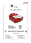
![or BTK [C481S] (cat. # CK-01-1002-384)](http://vs1.manualzilla.com/store/data/005787023_1-2d29b83e06663168d351d396f31f02d5-150x150.png)
