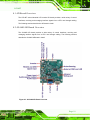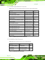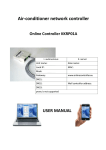
1
LCD-KIT IEI Te c h n o lo g y Co rp . MODEL: LCD-KIT S e rie s 15" ~ 17" Op e n Fra m e LCD Mo n ito r VGA, DVI-D, Ro HS Us e r Ma n u a l Page i Re v. 3.00 – 25 J u n e , 2013 LCD-KIT Re vis io n Date Version Changes 25 June, 2013 3.00 Initial release P a g e ii LCD-KIT Co p yrig h t COP YRIGHT NOTICE The information in this document is subject to change without prior notice in order to improve reliability, design and function and does not represent a commitment on the part of the manufacturer. In no event will the manufacturer be liable for direct, indirect, special, incidental, or consequential damages arising out of the use or inability to use the product or documentation, even if advised of the possibility of such damages. This document contains proprietary information protected by copyright. All rights are reserved. No part of this manual may be reproduced by any mechanical, electronic, or other means in any form without prior written permission of the manufacturer. TRADEMARKS All registered trademarks and product names mentioned herein are used for identification purposes only and may be trademarks and/or registered trademarks of their respective owners. P a g e iii LCD-KIT Ta b le o f Co n te n ts 1 INTRODUCTION.......................................................................................................... 1 1.1 LCD-KIT SERIES LCD MONITOR OVERVIEW ............................................................ 2 1.2 FEATURES ................................................................................................................... 2 1.3 MODEL VARIATIONS ................................................................................................... 3 1.4 APPLICATIONS ............................................................................................................ 3 1.5 EXTERNAL OVERVIEW ................................................................................................ 3 1.5.1 Front View .......................................................................................................... 3 1.5.2 Rear View ........................................................................................................... 4 1.5.3 Connectors ......................................................................................................... 5 1.5.4 AD Board ........................................................................................................... 6 1.6 SERIES SPECIFICATIONS .............................................................................................. 7 1.7 CERTIFICATIONS ......................................................................................................... 7 2 MECHANICAL OVERVIEW ...................................................................................... 8 2.1 INTRODUCTION........................................................................................................... 9 2.2 REAR PANEL ............................................................................................................... 9 2.3 CONNECTOR PANEL .................................................................................................... 9 2.3.1 Available Connectors ......................................................................................... 9 2.4 PHYSICAL DIMENSIONS ............................................................................................ 10 2.4.1 General Physical Dimensions .......................................................................... 10 2.4.2 LCD-KIT150G Physical Dimensions ................................................................ 11 2.4.3 LCD-KIT170G Physical Dimensions ............................................................... 12 2.5 MOUNTING OPTIONS ................................................................................................ 13 3 LCD SPECIFICATIONS ............................................................................................ 14 3.1 LCD SPECIFICATIONS ............................................................................................... 15 3.1.1 LCD Overview ................................................................................................. 15 3.1.2 LCD-KIT150G LCD Specifications ................................................................. 15 3.1.3 LCD-KIT170G LCD Specifications ................................................................. 16 3.2 POWER ADAPTERS .................................................................................................... 16 4 AD BOARD................................................................................................................... 18 P a g e iv LCD-KIT 4.1 AD BOARD OVERVIEW ............................................................................................. 19 4.2 AV-6600 AD BOARD OVERVIEW .............................................................................. 19 4.2.1 AV-6600 Peripheral Interface Connectors ....................................................... 20 4.2.2 AV-6600 Rear Panel Connectors ..................................................................... 20 5 INSTALLATION ......................................................................................................... 21 5.1 INSTALLATION PRECAUTIONS ................................................................................... 22 5.2 UNPACKING .............................................................................................................. 23 5.2.1 Packaging ........................................................................................................ 23 5.2.2 Unpacking Procedure ...................................................................................... 23 5.2.3 Packing List ..................................................................................................... 24 5.3 PRE-INSTALLATION PREPARATION ............................................................................ 24 5.3.1 Tools ................................................................................................................. 24 5.4 CONNECTORS ........................................................................................................... 25 5.4.1 VGA Connector ................................................................................................ 25 5.4.2 DVI-D Connector ............................................................................................. 25 5.4.3 12V Power Connector ...................................................................................... 26 5.4.4 Optional Terminal Block .................................................................................. 26 5.5 MOUNTING THE LCD-KIT SERIES LCD MONITOR .................................................. 27 6 OSD CONTROLS ........................................................................................................ 28 6.1 USER MODE OSD STRUCTURE ................................................................................. 29 6.1.1 OSD Buttons..................................................................................................... 29 6.1.2 OSD Menu Structure ........................................................................................ 29 6.2 USING THE OSD ....................................................................................................... 30 6.2.1 Main Display Features ..................................................................................... 30 6.2.2 Color ................................................................................................................ 31 6.2.3 OSD Configurations......................................................................................... 33 7 SOFTWARE DRIVER ................................................................................................ 34 7.1 INTRODUCTION......................................................................................................... 35 7.2 RS-232 OR USB TOUCH SCREEN ............................................................................. 35 7.3 TOUCH PANEL DRIVER INSTALLATION ...................................................................... 36 7.4 CHANGE THE TOUCH SCREEN INTERFACE ................................................................ 39 7.5 CALIBRATING THE TOUCH SCREEN ........................................................................... 39 Page v LCD-KIT A CERTIFICATIONS .................................................................................................... 42 A.1 ROHS COMPLIANT .................................................................................................. 43 B SAFETY PRECAUTIONS ......................................................................................... 44 B.1 SAFETY PRECAUTIONS ............................................................................................. 45 B.1.1 General Safety Precautions ............................................................................. 45 B.1.2 Anti-static Precautions .................................................................................... 46 B.2 MAINTENANCE AND CLEANING PRECAUTIONS ........................................................ 46 B.2.1 Maintenance and Cleaning.............................................................................. 46 B.2.2 Cleaning Tools ................................................................................................. 47 C SMARTOSD ................................................................................................................ 48 C.1 IEI SMARTOSD QUICK INSTALLATION GUIDE ......................................................... 49 C.2 PRE-INSTALLATION NOTICE ..................................................................................... 49 C.3 SMARTOSD INSTALL ............................................................................................... 50 C.4 SOFTWARE ILLUSTRATION ....................................................................................... 54 C.4.1 Manage Page................................................................................................... 56 C.4.2 EDID Page ...................................................................................................... 57 C.4.3 Image Page ...................................................................................................... 58 C.4.4 Display Page (for analog signal) .................................................................... 59 C.4.5 Color Page ...................................................................................................... 60 C.4.6 PIP Page.......................................................................................................... 61 C.4.7 System Page..................................................................................................... 62 C.4.8 About Page ...................................................................................................... 64 C.5 SMARTOSD FAQ ..................................................................................................... 65 C.5.1 Windows 2000 Installation Failure ................................................................. 65 C.5.2 Vista Installation Failure ................................................................................. 66 C.5.3 Model Failure .................................................................................................. 67 C.5.4 DCC Port Failure ............................................................................................ 67 P a g e vi LCD-KIT Lis t o f Fig u re s Figure 1 1: LCD-KIT Series ............................................................................................................2 Figure 1-2: Typical LCD-KIT Front View .......................................................................................4 Figure 1-3: Typical LCD-KIT Rear View ........................................................................................5 Figure 1-4: Typical LCD-KIT Connectors .....................................................................................5 Figure 1-5: AV-6600 AD Board ......................................................................................................6 Figure 2-1: Rear Panel ....................................................................................................................9 Figure 2-2: LCD-KIT150G Physical Dimensions (millimeters) .................................................11 Figure 2-3: LCD-KIT170G Physical Dimensions (millimeters) .................................................12 Figure 4-1: AV-6600 AD Board Overview ...................................................................................19 Figure 5-1: VGA Connector .........................................................................................................25 Figure 5-2: DVI-D Connector .......................................................................................................26 Figure 5-3: 12V Power Connector ...............................................................................................26 Figure 5-4: Terminal Block ..........................................................................................................27 Figure 6-1: OSD Control Buttons ................................................................................................29 Figure 6-2: Main Display Features ..............................................................................................31 Figure 6-3: Color Options ............................................................................................................32 Figure 6-4: OSD Configurations Menu .......................................................................................33 Figure 7-1: Setup Icon ..................................................................................................................36 Figure 7-2: Welcome Screen .......................................................................................................37 Figure 7-3: License Agreement ...................................................................................................37 Figure 7-4: Initiate Install .............................................................................................................38 Figure 7-5: Installation Starts ......................................................................................................38 Figure 7-6: Finish Installation ......................................................................................................39 Figure 7-7: PenMount Monitor Icon ............................................................................................40 Figure 7-8: PenMount Monitor Popup Menu ..............................................................................40 Figure 7-9: Configuration Screen ................................................................................................40 Figure 7-10: Calibration Initiation Screen ..................................................................................41 Figure 7-11: Calibration Screen ..................................................................................................41 Figure C-1: smartOSD Installer ...................................................................................................50 Figure C-2: smartOSD Welcome Screen ....................................................................................51 P a g e vii LCD-KIT Figure C-3: smartOSD Folder Select Screen .............................................................................51 Figure C-4: smartOSD Confirm Installation ...............................................................................52 Figure C-5: smartOSD Installation Progress .............................................................................52 Figure C-6: smartOSD Installation Complete ............................................................................53 Figure C-7: smartOSD Desktop Icon ..........................................................................................53 Figure C-8: Manage Page .............................................................................................................56 Figure C-9: EDID Page..................................................................................................................57 Figure C-10: Image Page ..............................................................................................................58 Figure C-11: Display Page ...........................................................................................................59 Figure C-12: Color Page ...............................................................................................................60 Figure C-13: PIP Page ..................................................................................................................61 Figure C-14: System Page ...........................................................................................................62 Figure C-15: About Page ..............................................................................................................64 Figure C-16: DLL Missing ............................................................................................................65 Figure C-17: Windows Vista Error ..............................................................................................66 Figure C-18: Install as Administrator..........................................................................................66 Figure C-19: Firmware Incompatibility .......................................................................................67 Figure C-20: DCC Port Failure .....................................................................................................67 P a g e viii LCD-KIT Lis t o f Ta b le s Table 1-1: LCD-KIT Series Model Variations ................................................................................3 Table 2-1: General Physical Dimensions ...................................................................................10 Table 2-2: Mounting Holes ...........................................................................................................13 Table 3-1: LCD-KIT150G LCD Specifications .............................................................................16 Table 3-2: LCD-KIT170G LCD Specifications .............................................................................16 Table 3-3: Power Adapter Specifications ...................................................................................17 Table 4-1: AV-6600 Peripheral Interface Connectors ................................................................20 Table 4-2: AV-6600 Rear Panel Connectors ...............................................................................20 Table 5-1: Rear Panel Connectors ..............................................................................................25 Table 5-2: VGA Connector Pinouts .............................................................................................25 Table 5-3: DVI-D Connector Pinouts ...........................................................................................26 Table 6-1: OSD Menus ..................................................................................................................30 Table C-1: SmartOSD Menu Structure ........................................................................................55 P a g e ix LCD-KIT Ch a p te r 1 1 In tro d u c tio n Page 1 LCD-KIT 1.1 LCD-KIT S e rie s LCD Mo n ito r Ove rview Figure 1 1: LCD-KIT Series The LCD-KIT series LCD monitor is the latest member of IEI’s line of sophisticated LCD designs, and it has been improved to be RoHS compliant. It is designed to fit industrial automation, or any other applications that require minimum installation space and flexible configuration. Flexible analog or digital interfaces are provided for ease of connection with a management computer. If remote/non-attentive control is preferred, RS-232 or USB interfaces can be used with customized adapter cables. 1.2 Fe a tu re s The LCD-KIT series have the following standard features: Page 2 Analog VGA interface supports most general system boards 350 nits (LCD-KIT170) / 400 nits (LCD-KIT150) high brightness Over 50,000 hrs MTBF long lifetime panel Advanced thermal and air-flow design Supports panel mounting 12 V DC power input via adapter M models have 9~36 V DC power connector Long product life support RoHS compliant LCD-KIT 1.3 Mo d e l Va ria tio n s The LCD-KIT series offers the following model variations. Model Number LCD-KIT150G-R30 LCD-KIT150GM-R30 LCD 9~36V Power 15” LCD-KIT170G-R30 LCD-KIT170GM-R30 Input Yes - 17” Yes Table 1-1: LCD-KIT Series Model Variations 1.4 Ap p lic a tio n s IEI’s series of LCD monitors are designed for system manufacturers, integrators, or value-added resellers that want to provide all the performance, quality and reliability of an LCD display solution at a cost effective price. IEI’s LCD kits offer additional components such as cables, an inverter and power supply with controller interfaces that include VGA and DVI. 1.5 Exte rn a l Ove rview The following sections describe the physical layout of the LCD-KIT series LCD monitors. 1.5.1 Fro n t Vie w The front of the LCD-KIT series LCD monitor is a flat panel TFT LCD screen attached to a metal chassis. Figure 1-2 shows a typical LCD-KIT front view. Page 3 LCD-KIT Figure 1-2: Typical LCD-KIT Front View 1.5.2 Re a r Vie w The rear of the LCD-KIT series LCD monitor is a metal chassis. An on screen display (OSD) control button panel, if present, is located vertically on the left side of the chassis with the following control buttons: LCD On/Off Auto Left Right Menu The OSD panel also has one power LED. Figure 1-3 shows a typical LCD-KIT rear panel. Page 4 LCD-KIT Figure 1-3: Typical LCD-KIT Rear View 1.5.3 Co n n e c to rs Each LCD-KIT series LCD monitor has a number of interface connectors on either the top or right panel of the chassis (when viewing the rear panel). Figure 1-4 shows a typical LCD-KIT connector panel. Each model may include or exclude additional connectors. Refer to Section 2.3 for listings of LCD-KITs and their connectors. All connectors are fully described in Section 5.4. Figure 1-4: Typical LCD-KIT Connectors Page 5 LCD-KIT 1.5.4 AD Bo a rd The LCD-KIT series LCD monitor AD boards provide a wide variety of control interfaces, receiving and managing signals from a CPU card through cabling. Figure 1-5 shows the AV-6600 AD board as a sample of a typical AD board for the LCD-KIT series LCD monitor. Refer to Chapter 4 for a complete description of AD boards and their connectors. Figure 1-5: AV-6600 AD Board Page 6 LCD-KIT 1.6 S e rie s Sp e c ific a tio n s The table below shows the LCD-KIT Series specifications. LCD-KIT LCD-KIT150G LCD Type LCD-KIT150GM LCD-KIT170G LCD-KIT170GM 15" TFT 15" TFT 17" TFT 17" TFT 1024 x 768 1024 x 768 1024 x 768 1024 x 768 400 400 350 350 Contrast Ratio 700:1 700:1 800:1 800:1 Display Color 16.2M 16.2M 16.7M 16.7M Pixel Pitch (mm) 0.297 0.297 0.264 0.264 Viewing Angle (H/V) 160/140 160/140 170/160 170/160 AD Board AV-6600 AV-6600 AV-6600 AV-6600 Analog VGA Analog VGA Analog VGA Analog VGA + DVI-D + DVI-D + DVI-D + DVI-D OSD function Yes Yes Yes Yes Smart-OSD Yes Yes Yes Yes 364.1 x 262.1 x 41.3 390.4 x 299.6 x 46.3 390.4 x 299.6 x 46.3 -10°C~50°C -10°C~50°C -10°C~50°C -10°C~50°C -20°C~60°C -20°C~60°C -20°C~60°C -20°C~60°C Net Weight 3.8 kg 3.8 kg 6 kg 6 kg Input Voltage 12VDC 9~36VDC 12VDC 9~36VDC 60W N/A 60W N/A CE CE Internal Prescan Internal Prescan EMC Class A EMC Class A Resolution Brightness (cd/m2) Input Interface Dimensions (WxHxD) 364.1 x 262.1 x (mm) 41.3 Operating Temperature Storage Temperature Power Adapter Certificates 1.7 Ce rtific a tio n s All LCD-KIT series LCD monitor models comply with the following international standards: RoHS For a more detailed description of these standards, please refer to Appendix A. Page 7 LCD-KIT Ch a p te r 2 2 Me c h a n ic a l Ove rvie w Page 8 LCD-KIT 2.1 In tro d u c tio n This chapter describes the general mechanical overview of the LCD-KIT series LCD monitors including rear panel variations, available interfaces and overall dimensions. 2.2 Re a r P a n e l The following models of the LCD-KIT series LCD monitor have an OSD control panel located vertically along the left side of the rear panel: LCD-KIT150G LCD-KIT170G Figure 2-1 shows the location of the rear panel OSD controls. Figure 2-1: Rear Panel 2.3 Co n n e c to r P a n e l All external peripheral interface connectors are located on the rear panel of the LCD-KIT series LCD monitor. The following sections describe the rear panel variants and their associated connectors. 2.3.1 Ava ila b le Co n n e c to rs There are a number of rear panel peripheral device connectors available for the LCD-KIT series LCD monitor. Page 9 LCD-KIT VGA connector DVI-D connector 12 V DC power connector 9~36 V DC power connector (M model only) 2.4 P h ys ic a l Dim e n s io n s The following sections describe the physical dimensions for each model of the LCD-KIT series LCD monitor. 2.4.1 Ge n e ra l P h ys ic a l Dim e n s io n s General physical dimensions for the LCD-KIT series LCD monitors are shown in Table 2-1. Mo d e l Wid th (m m ) He ig h t (m m ) De p th (m m ) LCD-KIT150G 364.1 262.5 41.9 LCD-KIT170G 390.4 300 46.9 Table 2-1: General Physical Dimensions P a g e 10 LCD-KIT 2.4.2 LCD-KIT150G P h ys ic a l Dim e ns io n s The physical dimensions of the LCD-KIT150G are shown in Figure 2-2. Figure 2-2: LCD-KIT150G Physical Dimensions (millimeters) P a g e 11 LCD-KIT 2.4.3 LCD-KIT170G P h ys ic a l Dim e ns io n s The physical dimensions of the LCD-KIT170GS are shown in Figure 2-3. Figure 2-3: LCD-KIT170G Physical Dimensions (millimeters) P a g e 12 LCD-KIT 2.5 Mo u n tin g Op tio n s Each LCD-KIT series LCD monitor has mounting holes located on the mounting bracket. Table 2-2 details the number of mounting holes for each model of the LCD-KIT series LCD monitor. Refer to Section 2.4 for more information. Mo d e l No . o f Ro u n d Ho le s - S ize No . o f S lo tte d Ho le s LCD-KIT170G 6 – 4.5 mm diameter 8 LCD-KIT150G 6 – 4.5 mm diameter 8 Table 2-2: Mounting Holes P a g e 13 LCD-KIT Ch a p te r 3 3 LCD S p e c ific a tio n s P a g e 14 LCD-KIT 3.1 LCD Sp e c ific a tio ns 3.1.1 LCD Ove rvie w The LCD-KIT series industrial LCD monitors use the following LCD panels. LCD-KIT150G: AUO G150XG01 V3 LCD-KIT170G: AUO G170EG01 V1 Detailed specifications for the LCD screens are listed in the following sections. 3.1.2 LCD-KIT150G LCD Sp e c ific a tio n s The table below lists the LCD-KIT150G LCD specifications. Ite m s LCD-KIT150G S ize 15” Bra n d AUO Mo d e l G150XG01 V3 Ba c klig h t LED Brig h tn e s s (c d /m 2) 400 Re s o lu tio n 1024 x 768 S c re e n S c a le 4:3 Life Tim e 50000H Co n tra s t Ra tio 700:1 Vie w An g le (H/V) 160/140 In te rfa c e 1ch LVDS Op e ra tin g Te m p e ra tu re -30~85°C Ac tive Are a (m m ) 304.1 x 228.1 P ixe l P itc h (m m ) 0.297 Mo d e Normal White Nu m b e r o f Co lo rs 16.2M P a g e 15 LCD-KIT S u p p ly Vo lta g e (V) 3.3 Table 3-1: LCD-KIT150G LCD Specifications 3.1.3 LCD-KIT170G LCD Sp e c ific a tio n s The table below lists the LCD-KIT170G LCD specifications. Ite m s LCD-KIT170G S ize 17” Bra n d AUO Mo d e l G170EG01 V1 Ba c klig h t LED Brig h tn e s s (c d /m 2) 350 Re s o lu tio n 1280 x 1024 S c re e n S c a le 4:3 Life Tim e 50000H Co n tra s t Ra tio 800:1 Vie w An g le (H/V) 170/160 In te rfa c e 2ch LVDS Op e ra tin g Te m p e ra tu re -30~70°C Ac tive Are a (m m ) 337.9 x 270.3 P ixe l P itc h (m m ) 0.264 Mo d e Normal White Nu m b e r o f Co lo rs 16.7M S u p p ly Vo lta g e (V) 5 Table 3-2: LCD-KIT170G LCD Specifications 3.2 P owe r Ad a p te rs Table 3-3 lists the power adapter specifications. P a g e 16 LCD-KIT LCD-KIT 150G, 170G Power 60W power adapter Input Voltage Range 90-264VAC Input Frequency 47-63 Hz Input AC Current 1.5A max @ 90vac input & full load Hold Time 8mS minimum. Tested 115 Vac input and max load at output 20mS minimum. Tested 230 Vac input and max load at output Leakage Current At 264 Vac 60Hz, 0.25mA max. MTBF 100Khrs (continuous operation at 25°C, maximum-output load, and nominal AC input voltage) EMI Standards EN 55022:1998 + A1:2000 +A2:2003 CLASS B CISPR22:2003 CLASS B AS/NZS CISPR22:2004 CLASS B Table 3-3: Power Adapter Specifications P a g e 17 LCD-KIT Ch a p te r 4 4 AD Bo a rd P a g e 18 LCD-KIT 4.1 AD Bo a rd Ove rvie w The LCD-KIT series industrial LCD monitor AD board provides a wide variety of control interfaces, receiving and managing interface signals from a CPU card through cabling. The following sections describe the AD board in detail. 4.2 AV-6600 AD Bo a rd Ove rview The AV-6600 AD board provides a wide variety of control interfaces, receiving and managing interface signals from a CPU card through cabling. The following sections describe the AV-6600 AD board in detail. Figure 4-1: AV-6600 AD Board Overview P a g e 19 LCD-KIT 4.2.1 AV-6600 P e rip he ra l Inte rfa c e Co n n e c to rs Table 4-1 shows a list of the peripheral interface connectors on the AV-6600 AD board. Co n n e c to r Typ e La b e l Audio input connector 4-pin wafer connector CN11 Audio speaker output connector 4-pin wafer connector CN12 Auto-dimming connector 6-pin wafer connector CN7 Debug connector 4-pin wafer connector CN9 External OSD and LED indication connector 9-pin wafer connector CN10 Infrared connector 6-pin wafer connector CN8 Inverter interface connector 6-pin wafer connector CN6 LVDS connector 30-pin connector CN5 Power output connector (+12 V) 2-pin wafer connector CN3 Power output connector (+5 V) 2-pin wafer connector CN4 Power input connector 3-pin connector CN2 RS-232 and USB signal input connector 12-pin wafer connector CN14 Touchscreen connector 9-pin wafer connector J4 VGA connector 10-pin box header VGA2 Table 4-1: AV-6600 Peripheral Interface Connectors 4.2.2 AV-6600 Re a r P a n e l Co n n e c to rs Table 4-2 lists the rear panel connectors on the AV-6600 AD board. Co n n e c to r Typ e La b e l 12V DC power connector DC Power Jack CN13 DVI connector 24-pin DVI-D connector J2 VGA connector 15-pin VGA connector VGA1 Table 4-2: AV-6600 Rear Panel Connectors P a g e 20 LCD-KIT Ch a p te r 5 5 In s ta lla tio n P a g e 21 LCD-KIT 5.1 In s ta lla tio n P re c a u tio n s When installing the LCD-KIT series LCD monitor, please follow the precautions listed below: Read the user manual: The user manual provides a complete description of the LCD-KIT series LCD monitor, installation instructions and configuration options. DANGER! Disconnect Power: Power to the LCD monitor must be disconnected when installing the LCD-KIT series LCD monitor, or before any attempt is made to access the rear panel. Electric shock and personal injury might occur if the rear panel of the monitor is opened while the power cord is still connected to an electrical outlet. Qualified Personnel: The LCD-KIT series LCD monitor must be installed and operated only by trained and qualified personnel. Maintenance, upgrades, or repairs may only be carried out by qualified personnel who are familiar with the associated dangers. Mounting: Since the monitor may weigh up to 10 kg (not including a swing arm or other accessories), please ensure at least two people assist with mounting the monitor. Air Circulation: Make sure there is sufficient air circulation when installing the monitor. The monitor’s cooling vents must not be obstructed by any objects. Blocking the vents can cause overheating of the monitor. Leave at least 5 cm of clearance around the monitor to prevent overheating. Grounding: The monitor should be properly grounded. The voltage feeds must not be overloaded. Adjust the cabling and provide external overcharge protection per the electrical values indicated on the label attached to the back of the monitor. Anti-static Discharge: The rear panel of the monitor must to be removed to configure the monitor’s AD board voltage select jumper. When doing so, be sure the monitor is disconnected from its power source and take all necessary safety precautions to avoid electrocution and static discharge to the AD board. The use of a grounded wrist strap and an anti-static work pad is recommended. P a g e 22 LCD-KIT 5.2 Un pa c kin g 5.2.1 P a c ka g in g When shipped, the LCD-KIT series LCD monitor is wrapped in a plastic bag. Two polystyrene ends are placed on either side of the monitor. The monitor is then placed into a first (internal) cardboard box. This box is then sealed and placed into a second (external) cardboard box. The second box is also sealed. A bag containing accessory items is placed with the monitor in the internal (first) box. 5.2.2 Un pa c kin g P ro c e d u re To unpack the LCD-KIT series LCD monitor, follow the steps below: WARNING: The front side LCD screen has a protective plastic cover stuck to the screen. Only remove the plastic cover after the LCD-KIT series LCD monitor has been properly installed. This ensures the screen is protected during the installation process. S te p 1: Use box cutters, a knife or a sharp pair of scissors that seals the top side of the external (second) box. S te p 2: Open the external (second) box. S te p 3: Use box cutters, a knife or a sharp pair of scissors that seals the top side of the internal (first) box. S te p 4: Lift the monitor out of the boxes. S te p 5: Remove both polystyrene ends, one from each side. S te p 6: Pull the plastic cover off the LCD-KIT series LCD monitor. S te p 7: Make sure all the components listed in the packing list are present. S te p 0: P a g e 23 LCD-KIT 5.2.3 P a c kin g Lis t All the monitors in the LCD-KIT series are shipped with the following components: 1 x LCD-KIT series LCD monitor. 1 x AC Power cable 1 x VGA Cable 1 x 60W Power Adapter 5 x Replacement Round Head Screw 5 x Replacement Flat Head Screw 5 x Replacement Wire Strain Band 1 x Utility CD If any of these items are missing or damaged, contact the distributor or sales representative immediately. 5.3 P re -in s ta lla tio n P re pa ra tio n 5.3.1 To o ls Before installing the LCD-KIT series LCD monitor, make sure the following tools are on hand: Philips (crosshead) screwdriver: All the retention screws on the system are Philips screws. Soft working mat: When the LCD-KIT series LCD monitor is installed, the screen is placed on the working surface. It is therefore important to rest the MPC industrial workstation on a soft mat that cannot damage the LCD screen on the front of the LCD-KIT series LCD monitor. P a g e 24 LCD-KIT 5.4 Co n n e c to rs Table 5-1 lists the rear panel connectors for the LCD-KIT series LCD monitors. LCD-KIT 150G 150GM 170G 170GM DVI-D Yes Yes Yes Yes VGA Yes Yes Yes Yes Power (12V Jack) Yes Yes Yes Yes - Yes - Yes Power (9~36V Terminal Block) (Optional for M model) Table 5-1: Rear Panel Connectors 5.4.1 VGA Co n n e c to r Use the rear panel standard 15-pin female VGA connector to connect the LCD monitor to the system graphics interface. Pin Description Pin Description Pin Description 1 RED 6 GROUND 11 NC 2 GREEN 7 GROUND 12 DDCDAT 3 BLUE 8 GROUND 13 HSYNC 4 NC 9 NC 14 VSYNC 5 GROUND 10 GROUND 15 DDCCLK Table 5-2: VGA Connector Pinouts Figure 5-1: VGA Connector 5.4.2 DVI-D Co n n e c to r Use the rear panel standard 24-pin female DVI-D connector to connect the LCD monitor to the system graphics interface. P a g e 25 LCD-KIT Pin Description Pin Description Pin Description 1 TMDS Data2- 9 TMDS Data1- 17 TMDS Data0- 2 TMDS Data2+ 10 TMDS Data1+ 18 TMDSData0+ 3 TMDS Data2/4 Shield 11 TMDS Data1/3 Shield 19 TMDS Data0/5 Shield 4 TMDS Data4- 12 TMDS Data3- 20 TMDS Data5- 5 TMDS Data4+ 13 TMDS Data3+ 21 TMDS Data5+ 6 DDC Clock [SCL] 14 +5 V Power 22 TMDS Clock Shield 7 DDC Data [SDA] 15 Ground (for +5 V) 23 TMDS Clock + 8 Analog vertical sync 16 Hot Plug Detect 24 TMDS Clock - Table 5-3: DVI-D Connector Pinouts Figure 5-2: DVI-D Connector 5.4.3 12V P owe r Co n n e c to r Use the rear panel +12V DC (or 9~36V DC on M models) jack to connect the monitor to a power source. Figure 5-3: 12V Power Connector 5.4.4 Op tio n a l Te rm in a l Blo c k Use the rear panel 3-pin terminal block DC power connector to connect the monitor to a DC power source. P a g e 26 LCD-KIT Figure 5-4: Terminal Block 5.5 Mo u n tin g th e LCD-KIT S e rie s LCD Mo n ito r Each LCD-KIT series LCD monitor comes with a preinstalled mounting bracket with a number of holes available for mounting purposes that system integrators will find especially useful. Refer to Sections 2.4 and 2.5 for further details on the number and location of mounting holes for each model of the LCD-KIT series LCD monitor. P a g e 27 LCD-KIT Ch a p te r 6 6 OS D Co n tro ls P a g e 28 LCD-KIT 6.1 Us e r Mo d e OS D Stru c tu re 6.1.1 OS D Bu tto n s There are several on-screen-display (OSD) control buttons oriented vertically along the left side of the monitor rear panel. Figure 6-1 shows a typical arrangement of OSD controls of the LCD-KIT series LCD monitor. Figure 6-1: OSD Control Buttons 6.1.2 OS D Me n u Stru c tu re Table 6-1 shows the OSD menu structure for all models of the SRM series LCD monitor. Level 0 Level 1 Value Main Display Features Menu Brightness 0 to 100 Contrast 0 to 100 P a g e 29 LCD-KIT Color Menu OSD Menu Exit Menu Clock 0 to 100 Phase 0 to 100 H. Position 0 to 100 V. Position 0 to 100 Sharpness 1 to 5 6500K - Preset NTSC value 7500K - Preset NTSC value 9300K - Preset NTSC value Red RGB values from 0 to 100 Green RGB values from 0 to 100 Blue RGB values from 0 to 100 OSD Time Out 0 to 60 sec OSD Position 1 to 5 OSD Transparency 20, 40, 60, 80, 100 Factory Reset Select Auto Adjust Select Auto Color Select Gamma Off, On Exit Select Table 6-1: OSD Menus 6.2 Us in g th e OS D OSD menu options are described below. 6.2.1 Ma in Dis p la y Fe a tu re s Main display features are shown in Figure 6-2. P a g e 30 LCD-KIT Figure 6-2: Main Display Features The brightness option adjusts the brightness of screen. This function Brightness adjusts the offset value of ADC. Setting this value too high or too low will affect the quality of image. When the auto- dimming function is turned on, the brightness control is not effective. Contrast This function adjusts the gain value of ADC. Adjusting this value too high or too low will worsen the quality of image. Clock Adjusts the width of the display screen. Phase Adjusts the input signal. H. Position Adjusts the horizontal position of the display screen. V. Position Adjusts the vertical position of the display screen Sharpness Adjust the sharpness of the display 6.2.2 Co lo r Color options are shown in Figure 6-3. P a g e 31 LCD-KIT Figure 6-3: Color Options The Color menu fine-tunes the palette of color hues for the LCD. 6500k NTSC standard Kelvin 7500k NTSC standard Kelvin 9300k NTSC standard Kelvin User P a g e 32 This item allows fine-tuning the balance among Red, Green, and Blue color hues if images look garish or unrealistic. LCD-KIT 6.2.3 OS D Co n fig u ra tio n s The OSD configurations are shown in Figure 6-4. Figure 6-4: OSD Configurations Menu OSD Configurations are described below. OSD Time Out Determines how many seconds the OSD screen stays on screen before it disappears when OSD is left unattended. Adjusts the OSD position on the screen. Position 1 is in the upper left OSD Position of the screen, position 2 in the upper right and position 3 in the center. OSD Transparency Adjust the transparency of the OSD menu background. Factory Reset Restores the default OSD settings. Note that this will restore all default display settings. Auto Adjust Automatically adjusts the position of the display screen Auto Color Automatically adjusts the color settings. P a g e 33 LCD-KIT Ch a p te r 7 7 S o ftwa re Drive r P a g e 34 LCD-KIT 7.1 In tro d u c tio n The touch panel controller enables analog resistive touch panels for four-wire, five-wire & eight-wire models. The controller directly communicates with the PC system through the touch panel communications interface. The controller design is superior in sensitivity, accuracy, and friendly operation. The touch panel driver emulates the left mouse button and the right mouse button functions. The touch panel driver supports the following operating systems: ® o o o o o o ® Microsoft Windows versions: ® ® ® ® ® ® ® ® ® ® ® ® Microsoft Windows 2000 Microsoft Windows XP Microsoft Windows 2003 Microsoft Windows 2008 Microsoft Windows Vista Microsoft Windows 7 ® ® Microsoft Windows CE versions: o o o ® ® ® ® ® ® Microsoft Windows CE 4.2 Microsoft Windows CE 5.0 Microsoft Windows CE 6.0 Linux Kernel 2.6 DOS Driver installation is described below. 7.2 RS -232 o r US B To u c h S c re e n Before installing the driver, connect the LCD-KIT monitor to the motherboard. The LCD-KIT monitors support touch screen modality through an RS-232 or USB interface connection. Decide through which interface the touch screen is to be controlled. RS-232 Interface: If the touch screen interface connection is an RS-232 connection, connect the RS-232 connector on the single board computer to the DB-9 connector of the LCD-KIT monitor. P a g e 35 LCD-KIT USB Interface: If the touch screen interface connection is a USB connection, connect the USB connector on the single board computer to the external USB port connector of the LCD-KIT monitor. 7.3 To u c h P a n e l Drive r In s ta lla tio n WARNING: Before the touch screen driver is installed, make sure the system is connected to the monitor with a USB cable or an RS-232 null cable. Also, make sure the VGA connector on the system is connected to the VGA connector on the bottom of the monitor. To install the touch panel driver for the LCD-KIT, please follow the instructions below: S te p 1: Connect the LCD-KIT monitor to the single board computer. See above. S te p 2: Install the driver CD. Install the driver CD into the system to which the LCD-KIT monitor is connected. S te p 3: Select the Touch Screen option in the menu of driver CD. The directory in Figure 7-1 appears. Figure 7-1: Setup Icon P a g e 36 LCD-KIT S te p 4: Double click the setup icon in Figure 7-1. S te p 5: The Welcome screen in Figure 7-2 appears. Figure 7-2: Welcome Screen S te p 6: Click Next to continue. S te p 7: The license agreement in Figure 7-3 appears. Accept the terms of the agreement by clicking I Agree. Figure 7-3: License Agreement P a g e 37 LCD-KIT S te p 8: The installation destination screen appears. See Figure 7-4. Click Install. Figure 7-4: Initiate Install S te p 9: The installation of the program begins. See Figure 7-5. Figure 7-5: Installation Starts S te p 10: When the installation is complete, the complete screen appears. See Figure 7-6. To complete the installation process click Finish. P a g e 38 LCD-KIT Figure 7-6: Finish Installation 7.4 Ch a n g e th e To u c h S c re e n In te rfa c e If the touch screen interface must be changed from an RS-232 interface to a USB interface or, from a USB interface to an RS-232 interface, the following steps must be followed. S te p 1: Uninstall the touch screen driver S te p 2: Remove the interface cable i.e. remove the RS-232 cable or the USB cable S te p 3: Install the new cable i.e. install the USB cable or the RS-232 cable. S te p 4: Reinstall the driver CD as described above. S te p 0: 7.5 Ca lib ra tin g th e To u c h S c re e n To calibrate the touch screen cursor with the motion of the touch screen pen (or finger), please follow the steps below: S te p 1: Make sure the system is properly connected through an RS-232 or a USB interface to the LCD-KIT monitor. S te p 2: Make sure the touch screen driver is properly installed. P a g e 39 LCD-KIT S te p 3: Locate the PenMount Monitor icon in the bottom left corner of the screen. Figure 7-7: PenMount Monitor Icon S te p 4: Click the icon. A pop up menu appears. See Figure 7-8. Figure 7-8: PenMount Monitor Popup Menu S te p 5: Click Control Panel in the pop up menu shown in Figure 7-8. S te p 6: The configuration screen in Figure 7-9 appears. Figure 7-9: Configuration Screen P a g e 40 LCD-KIT S te p 7: Double click the PenMount 6000 icon as shown in Figure 7-9. S te p 8: The calibration initiation screen in Figure 7-10 appears. S te p 9: Select the Standard Calibration button as shown in Figure 7-10. Figure 7-10: Calibration Initiation Screen S te p 10: The calibration screen in is shown. See Figure 7-11. Figure 7-11: Calibration Screen S te p 11: Follow the instructions. The user is asked touch the screen at five specified points after which the screen is calibrated. S te p 0: P a g e 41 LCD-KIT Ap p e n d ix A A Ce rtific a tio n s P a g e 42 LCD-KIT A.1 Ro HS Co m p lia n t All models in the LCD-KIT series comply with the Restriction of Hazardous Materials (RoHS) Directive. This means that all components used to build the industrial workstations and the workstation itself are RoHS compliant. The RoHS Directive bans the placing on the EU market of new electrical and electronic equipment containing more than agreed levels of lead, cadmium, mercury, hexavalent chromium, polybrominated biphenyl (PBB) and polybrominated diphenyl ether (PBDE) flame retardants. P a g e 43 LCD-KIT Ap p e n d ix B B S a fe ty P re c a u tio n s P a g e 44 LCD-KIT WARNING: The precautions outlined in this chapter should be strictly followed. Failure to follow these precautions may result in permanent damage to the LCD-KIT Series. B.1 S a fe ty P re c a u tio n s Please follow the safety precautions outlined in the sections that follow: B.1.1 Ge n e ra l S a fe ty P re c a u tio n s Please ensure the following safety precautions are adhered to at all times. Follow the electrostatic precautions outlined below whenever the LCD-KIT Series is opened. Make sure the power is turned off and the power cord is disconnected whenever the LCD-KIT Series is being installed, moved or modified. Do not apply voltage levels that exceed the specified voltage range. Doing so may cause fire and/or an electrical shock. Electric shocks can occur if the LCD-KIT Series chassis is opened when the LCD-KIT Series is running. Do not drop or insert any objects into the ventilation openings of the LCD-KIT Series. If considerable amounts of dust, water, or fluids enter the LCD-KIT Series, turn off the power supply immediately, unplug the power cord, and contact the LCD-KIT Series vendor. DO NOT: o o o o Drop the LCD-KIT Series against a hard surface. Strike or exert excessive force onto the LCD panel. Touch any of the LCD panels with a sharp object In a site where the ambient temperature exceeds the rated temperature P a g e 45 LCD-KIT B.1.2 An ti-s ta tic P re c a u tio n s WARNING: Failure to take ESD precautions during the installation of the LCD-KIT Series may result in permanent damage to the LCD-KIT Series and severe injury to the user. Electrostatic discharge (ESD) can cause serious damage to electronic components, including the LCD-KIT Series. Dry climates are especially susceptible to ESD. It is therefore critical that whenever the LCD-KIT Series is opened and any of the electrical components are handled, the following anti-static precautions are strictly adhered to. Wear an anti-static wristband: Wearing a simple anti-static wristband can help to prevent ESD from damaging any electrical component. Self-grounding: Before handling any electrical component, touch any grounded conducting material. During the time the electrical component is handled, frequently touch any conducting materials that are connected to the ground. Use an anti-static pad: When configuring or working with an electrical component, place it on an antic-static pad. This reduces the possibility of ESD damage. Only handle the edges of the electrical component: When handling the electrical component, hold the electrical component by its edges. B.2 Ma in te n a n c e a n d Cle a n in g P re c a u tio n s When maintaining or cleaning the LCD-KIT Series, please follow the guidelines below. B.2.1 Ma in te n a n c e a n d Cle a n in g Prior to cleaning any part or component of the LCD-KIT Series, please read the details below. P a g e 46 LCD-KIT Except for the LCD panel, never spray or squirt liquids directly onto any other components. To clean the LCD panel, gently wipe it with a piece of soft dry cloth or a slightly moistened cloth. The interior of the LCD-KIT Series does not require cleaning. Keep fluids away from the LCD-KIT Series interior. Be cautious of all small removable components when vacuuming the LCD-KIT Series. Turn the LCD-KIT Series off before cleaning the LCD-KIT Series. Never drop any objects or liquids through the openings of the LCD-KIT Series. Be cautious of any possible allergic reactions to solvents or chemicals used when cleaning the LCD-KIT Series. Avoid eating, drinking and smoking within vicinity of the LCD-KIT Series. B.2.2 Cle a n in g To o ls Some components in the LCD-KIT Series may only be cleaned using a product specifically designed for the purpose. In such case, the product will be explicitly mentioned in the cleaning tips. Below is a list of items to use when cleaning the LCD-KIT Series. Cloth – Although paper towels or tissues can be used, a soft, clean piece of cloth is recommended when cleaning the LCD-KIT Series. Water or rubbing alcohol – A cloth moistened with water or rubbing alcohol can be used to clean the LCD-KIT Series. Using solvents – The use of solvents is not recommended when cleaning the LCD-KIT Series as they may damage the plastic parts. Vacuum cleaner – Using a vacuum specifically designed for computers is one of the best methods of cleaning the LCD-KIT Series. Dust and dirt can restrict the airflow in the LCD-KIT Series and cause its circuitry to corrode. Cotton swabs - Cotton swaps moistened with rubbing alcohol or water are excellent tools for wiping hard to reach areas. Foam swabs - Whenever possible, it is best to use lint free swabs such as foam swabs for cleaning. P a g e 47 LCD-KIT Ap p e n d ix C C s m a rtOS D P a g e 48 LCD-KIT C.1 IEI s m a rtOS D Qu ic k In s ta lla tio n Gu id e IEI smartOSD is a proprietary On-Screen-Display (OSD) software solution from IEI that enables easy, remote monitor setting adjustments in a Windows environment. IEI smartOSD delivers excellent performance and provides more flexibility than the typical OSD hardware solutions when adjusting a monitor. smartOSD also allows monitor settings such as brightness, contrast, screen position, size, and color gain to be read and changed over normal video cable (VGA or DVI). The smartOSD function is only supported by revision 1.1 models and above. C.2 P re -in s ta lla tio n No tic e Before installing smartOSD software, please make sure one of the following operating systems is installed: Windows 95 Windows NT 4.0 Windows 98 Windows 2000 Windows 2003 Windows XP Windows Vista P a g e 49 LCD-KIT C.3 s m a rtOS D In s ta ll Connect the LCD-KIT to a host computer. Insert the CD that came with the system and follow the instructions below. S te p 1: When the CD installs the screen shown in Figure C-1 appears. Figure C-1: smartOSD Installer S te p 2: Click “Smart OSD” in Figure C-1. S te p 3: The welcome screen shown in Figure C-2 appears. P a g e 50 LCD-KIT Figure C-2: smartOSD Welcome Screen S te p 4: Click Next to continue. S te p 5: The Folder Select screen in Figure C-3 appears. Figure C-3: smartOSD Folder Select Screen S te p 6: Select the installation folder in Figure C-3 shown above. S te p 7: Click Next to continue. S te p 8: The screen in Figure C-4 appears. P a g e 51 LCD-KIT Figure C-4: smartOSD Confirm Installation S te p 9: Confirm the installation by clicking Next in the screen above. S te p 10: The program starts to install and the progress bar shown in Figure C-5 appears. Figure C-5: smartOSD Installation Progress S te p 11: When the installation is complete the “Complete Installation” screen in Figure C-6 appears. P a g e 52 LCD-KIT Figure C-6: smartOSD Installation Complete S te p 12: Click Close in the screen above. S te p 13: After quick setup is complete, the IEI smartOSD wizard logo appears on the desktop as shown in the screen below. S te p 14: To access the smartOSD, click the smartOSD wizard logo.S te p 0: Figure C-7: smartOSD Desktop Icon P a g e 53 LCD-KIT C.4 S o ftwa re Illu s tra tio n The table below shows the smartOSD menu structure for all IEI LCD monitors. NOTE: To update the display setting status immediately, push the refresh button on every page To turn the system on, press ALT + P. Ite m Ele m e n ts Ma n a g e m e n t Save/Load File Power Management EDID EDID contains basic information about the monitor and its capabilities. Im a g e Brightness Contrast Sharpness Dis p la y Auto Adjust Phase Clock Co lo r Auto Color User Red Gain User Green Gain User Blue Gain Color Temperature (5000k and 4200k disabled in the LCD-KIT Series) Gamma P IP P a g e 54 PIP (disabled in the LCD-KIT Series) LCD-KIT Ite m Ele m e n ts PIP Source Input (disabled in the LCD-KIT Series) PIP Size (disabled in the LCD-KIT Series) S ys te m Monitor Power Control Auto Brightness (disabled in the LCD-KIT Series) Main Source Input (S-Video and CVBS disabled) Volume (disabled in the LCD-KIT Series) Factory Presets/OSD Lock/OSD Unlock Mute (disabled in the LCD-KIT Series) Table C-1: SmartOSD Menu Structure P a g e 55 LCD-KIT C.4.1 Ma n a g e P a g e Figure C-8: Manage Page P a g e 56 LCD-KIT C.4.2 EDID P a g e Figure C-9: EDID Page P a g e 57 LCD-KIT C.4.3 Im a g e P a g e Figure C-10: Image Page P a g e 58 LCD-KIT C.4.4 Dis p la y P a g e (fo r a n a lo g s ig n a l) Figure C-11: Display Page P a g e 59 LCD-KIT C.4.5 Co lo r P a g e Figure C-12: Color Page P a g e 60 LCD-KIT C.4.6 P IP P a ge NOTE: The functions in the PIP page are only available in the MLCD-KIT Series and AFOLUX Series monitors. Figure C-13: PIP Page P a g e 61 LCD-KIT C.4.7 S ys te m P a g e Figure C-14: System Page P a g e 62 LCD-KIT NOTE: Some of the functions in the System Page are only available to some of the IEI LCD series as following: Auto Brightness: SRM, MLCD-KIT and AFOLUX series only Main Source Input: MLCD-KIT and AFOLUX series only Volume: AFOLUX series only Mute: AFOLUX series only P a g e 63 LCD-KIT C.4.8 Ab o u t P a g e Figure C-15: About Page P a g e 64 LCD-KIT C.5 s m a rtOS D FAQ For troubleshooting, please see the steps below: C.5.1 Win d ows 2000 In s ta lla tio n Fa ilu re Installation fails under Windows 2000 and shows the following image: Figure C-16: DLL Missing Solution: Download and install service pack Windows Installer 3.1 P a g e 65 LCD-KIT C.5.2 Vis ta In s ta lla tio n Fa ilu re Installation fails under Vista while showing following image: Figure C-17: Windows Vista Error Solution: Install SmartOSD.exe with administrator authority Figure C-18: Install as Administrator P a g e 66 LCD-KIT C.5.3 Mo d e l Fa ilu re The Model Fail error message shown below appears. Figure C-19: Firmware Incompatibility Solution: SmartOSD only supports firmware version 2.0 and following versions. C.5.4 DDC P o rt Fa ilu re The DDC port fail error message shown below appears. Figure C-20: DCC Port Failure Solutions: Check VGA or DVI cable Check an IEI monitor is being used Make sure the version is version 2.3 for the AFOLUX/MLCD-KIT series and version 1.5 for the LCD-KIT/ISLCD-KIT/TLCD-KIT/SRM/LCD-KIT series that have the SmartOSD functions Check if the OSD control status is busy. A busy signal may cause the signal message for a short time. P a g e 67