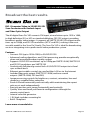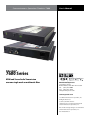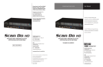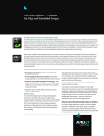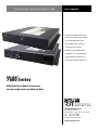
1
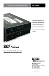
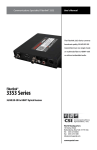
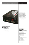
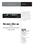
Communications Specialties’ Fiberlink® 7600
User’s Manual
Distribute HDMI and stereo
audio over one single mode
or multimode fiber with
no compression, scaling,
conversions or frame
dropping. The 7600 Series
is feature rich, including our
unique EDID function and
Pixel Clock phase selections.
Fiberlink®
7600 Series
HDMI with Stereo Audio Transmission
over one single mode or multimode fiber.
World Headquarters
125 Comac Street
Ronkonkoma, New York 11779 USA
Tel: (631) 273-0404
Fax: (631) 273-1638
[email protected]
commspecial.com
Fiberlink® 7600 Series
Contents
Contents
Welcome . . . . . . . . . . . . . . . . . . . . . . . . . . . . . . . . . . . . . . . . . . . . . . . . . . . . . . . . . . . . . . . . . . . . . . . . . . . . 3
Features. . . . . . . . . . . . . . . . . . . . . . . . . . . . . . . . . . . . . . . . . . . . . . . . . . . . . . . . . . . . . . . . . . . . . . . . . . . . . 3
Package Contents. . . . . . . . . . . . . . . . . . . . . . . . . . . . . . . . . . . . . . . . . . . . . . . . . . . . . . . . . . . . . . . . . . . . 3
Technical Specifications. . . . . . . . . . . . . . . . . . . . . . . . . . . . . . . . . . . . . . . . . . . . . . . . . . . . . . . . . . . . . . 4
7600 Transmitter Specifications. . . . . . . . . . . . . . . . . . . . . . . . . . . . . . . . . . . . . . . . . . . . . . . . . . . . . . . 4
HDMI Specifications. . . . . . . . . . . . . . . . . . . . . . . . . . . . . . . . . . . . . . . . . . . . . . . . . . . . . . . . . . . . . . . . . . 4
Audio Specifications . . . . . . . . . . . . . . . . . . . . . . . . . . . . . . . . . . . . . . . . . . . . . . . . . . . . . . . . . . . . . . . . . 4
7600 Transmitter Optical Specifications. . . . . . . . . . . . . . . . . . . . . . . . . . . . . . . . . . . . . . . . . . . . . . . 5
7601 Receiver HDMI Output. . . . . . . . . . . . . . . . . . . . . . . . . . . . . . . . . . . . . . . . . . . . . . . . . . . . . . . . . . 5
7601 Receiver Specifications . . . . . . . . . . . . . . . . . . . . . . . . . . . . . . . . . . . . . . . . . . . . . . . . . . . . . . . . . 6
7600 General Specifications. . . . . . . . . . . . . . . . . . . . . . . . . . . . . . . . . . . . . . . . . . . . . . . . . . . . . . . . . . 6
Installation Instructions. . . . . . . . . . . . . . . . . . . . . . . . . . . . . . . . . . . . . . . . . . . . . . . . . . . . . . . . . . . . . . 7
EDID Functions . . . . . . . . . . . . . . . . . . . . . . . . . . . . . . . . . . . . . . . . . . . . . . . . . . . . . . . . . . . . . . . . . . . . . . 8
EDID Functions (cont). . . . . . . . . . . . . . . . . . . . . . . . . . . . . . . . . . . . . . . . . . . . . . . . . . . . . . . . . . . . . . . . 9
Operating Tips. . . . . . . . . . . . . . . . . . . . . . . . . . . . . . . . . . . . . . . . . . . . . . . . . . . . . . . . . . . . . . . . . . . . . . . 9
Video Adjust Switch. . . . . . . . . . . . . . . . . . . . . . . . . . . . . . . . . . . . . . . . . . . . . . . . . . . . . . . . . . . . . . . . . . 9
Using 9-Volt Battery. . . . . . . . . . . . . . . . . . . . . . . . . . . . . . . . . . . . . . . . . . . . . . . . . . . . . . . . . . . . . . . . . . 9
Alarm Switch Settings & Options . . . . . . . . . . . . . . . . . . . . . . . . . . . . . . . . . . . . . . . . . . . . . . . . . . . . 10
Indicator LEDs . . . . . . . . . . . . . . . . . . . . . . . . . . . . . . . . . . . . . . . . . . . . . . . . . . . . . . . . . . . . . . . . . . . . . . 11
Operating Pointers. . . . . . . . . . . . . . . . . . . . . . . . . . . . . . . . . . . . . . . . . . . . . . . . . . . . . . . . . . . . . . . . . . 12
Troubleshooting. . . . . . . . . . . . . . . . . . . . . . . . . . . . . . . . . . . . . . . . . . . . . . . . . . . . . . . . . . . . . . . . . . . . 12
Maintenance. . . . . . . . . . . . . . . . . . . . . . . . . . . . . . . . . . . . . . . . . . . . . . . . . . . . . . . . . . . . . . . . . . . . . . . . 13
Certifications . . . . . . . . . . . . . . . . . . . . . . . . . . . . . . . . . . . . . . . . . . . . . . . . . . . . . . . . . . . . . . . . . . . . . . . 13
Warranty and Repairs . . . . . . . . . . . . . . . . . . . . . . . . . . . . . . . . . . . . . . . . . . . . . . . . . . . . . . . . . . . . . . . 14
Page 2
Fiberlink® 7600 Series User’s Manual
Fiberlink® 7600 Series
Welcome | Features | Package Contents
Welcome
Thank you for purchasing Communications Specialties, Inc.’s Fiberlink® 7600 Series. The
7600 Series is used to transmit pristine HDMI with stereo audio over a single fiber optic
core. Compatible with single mode or multimode fiber, the 7600 is ideal for the most
demanding of applications, from distance learning to rental and staging. The 7600 offers a
unique EDID function that allows you to generate EDID internally, or you can capture and
permanently store EDID information.
Features
•Supports HDMI resolutions up to 1920 x 1200 at 165 MHz pixel clock
and HDTV resolutions of 480p, 720p, 1080i, and 1080p
•Unique 0/180 degree pixel clock selection to compensate for HDMI cable skew
• Supports embedded stereo audio from the HDMI source
•Uses no compression, frame dropping, or scaling for crystal clear signals
•Only one fiber used - no pixel skewing
•Supports EDID from internal generation, or capture and storage.
•Transmits signals over one single mode or multimode fiber optic core.
•RoHS Compliant
Package Contents
•One Fiberlink® 7600 or 7601.
•This User’s Manual
Fiberlink® 7600 Series User’s Manual
Page 3
Technical Specifications
Fiberlink® 7600 Series
Technical Specifications
7600 Transmitter Specifications
Number of Inputs:
One HDMI up to 165MHz Pixel Clock
Connector: One female HDMI type A with screw lock
Spatial Resolutions:
480i, 480p, 720p, 1080i, 1080p, 1920x1200p; 50, 59.94 and 60 Hz vertical refresh
Color Resolutions:
8-Bits per pixel; pixel-for-pixel sampling
HDMI Embedded Audio: 2 channels
EDID: Ability to capture EDID from target monitor or internal default resolutions
Color Space Support: 8-Bit RGB or YCrCb
HDMI Specifications
HDCP: Compliant with High-bandwidth Digital
Content Protection (HDCP) using HDMI standards
HDMI Version Support:
v1.0: Fully supported v1.1: Fully supported v1.2: Fully supported
v1.2a: Fully supported (*)
v1.3: Fully supported (*)
v1.3a: Fully supported (*)
v1.4: Supported (*)(**)
v2.0: Supported (*)(**)
(*) 24-bit video, max video clock of 165MHz and 2ch PCM audio are enforced via
EDID protocol. CEC (Consumer Electronics Control) is not supported.
(**) ARC (Audio Return Channel) or HEC (HDMI Ethernet Channel) are not
supported.
Audio Specifications
Number of Audio Channels Page 4
2, unbalanced
Fiberlink® 7600 Series User’s Manual
Technical Specifications
Fiberlink® 7600 Series
Technical Specifications
7600 Transmitter Optical Specifications
Emitter Type
FP Laser
Operating Wavelength 1310nm Optimal
Optical Fibers SM: 8-10/125 microns;
MM: 50u or 62.5u
Optical Connector ST
Class I Laser Product complies with FDA performance standard for laser products,
Title 21, Code of Federal Regulations, Sub-Chapter J.
7601 Receiver HDMI Output
Number of Outputs
1
Connector
One Female HDMI type A with screw lock
Spatial Resolutions:
480i, 480p, 720p, 1080i, 1080p, 1920x1200p; 50, 59.94 and 60 Hz vertical refresh
Color Resolution: 8 bits per pixel; pixel-for-pixel sampling
HDMI Embedded Audio: 2 channels
Color Space Support: 8-Bit RGB or YCrCb
HDCP: Compliant with High-bandwidth Digital
Content Protection (HDCP) using HDMI standards
Fiberlink® 7600 Series User’s Manual
Page 5
Technical Specifications
Fiberlink® 7600 Series
7601 Receiver Specifications
Fiber Optic Input
Connector
ST
Wavelength
1100 - 1620 nm
Minimum Input Sensitivity
-17 dBm
Maximum Input Power
0 dBm
Link Budget with 7600 Transmitter: 0-14 dB
7600 General Specifications
LED Indicators
Power, Video, Audio,
Alarm (Card Version Only)
Box Version Dimensions
6.5w x 1.15h x 8l (in)
165 W x 29 H x 203 L (mm)
Weight
1 lb. (0.455 kg)
MTBF
32,000 hours
Power
9-24 volts, AC or DC,
7600: 5.3 watts, 18.0 BTU/Hr
7601: 4.7 watts, 16.0 BTU/Hr
Operating Temperature
-10º C to +45º C
Page 6
Fiberlink® 7600 Series User’s Manual
Installation Instructions
Fiberlink® 7600 Series
Installation Instructions
The Fiberlink® 7600 Series of fiber optic transmission system is ready for
immediate use and does not require any special tools or equipment. However, an Optical
Power Meter, such as the Fiberlink® 6650, can be useful in determining optical loss budgets
during your system’s design and system maintenance.
The following instructions describe the typical installation procedure:
1) Connect the HDMI video source to the video input HDMI
connector on the transmitter unit.
2) Determine your EDID requirements and follow the procedures described in the
“EDID Function” section of this manual.
3) Connect the video output on the receiver unit to the HDMI monitor or load.
4) Connect the fiber optic cable between the two Fiberlink units.
5) Apply power to both the Fiberlink units.
For box versions using DC power connections, refer to Figure 1.
6) When power is applied, the green POWER LED will light, indicating the presence
of operating power. The VIDEO LED will give an indication as described on page 13.
The green AUDIO LED will give an indication as stated on page 13.
7) The system should now be operational.
Note: The transmitter and receiver will each perform HDCP authentication with their source and
load. This will take several seconds to accomplish proper authentication.
Note: The Rack Card version has an additional red LED for indicating the presence of an alarm
condition (loss of signal). Refer to Indicator LED’s and Alarm Switch Settings & Options sections
of this manual.
The transmitting element in the Fiberlink® 7600 transmitter
unit contains a solid state Laser Diode located in the optical
connector. This device emits invisible infrared electromagnetic radiation which can be harmful to human eyes. The radiation from this optical connector, if viewed at close range
with no fiber optic cable connected to the optical connector,
may be sufficient intensity to cause instantaneous damage to the retina of the eye. Direct viewing of this radiation
should be avoided at all times!
Fiberlink® 7600 Series User’s Manual
Page 7
Installation Instructions | EDID Function
Fiberlink® 7600 Series
Installation Instructions (cont.)
Figure 1:
Power Connector
DC Input Polarity
(+) Positive
( - ) Negative
9-24 Volts
AC or DC
EDID Functions
The Fiberlink® 7600 Series of HDMI fiber optic transmission system has a unique “EDID”
feature set that allows the capture and storage of EDID information, or allows the generation of the EDID internally, on-the-fly. The procedures for implementing each feature are
described below.
Generating EDID internally when no EDID has been captured:
The 7600 Transmitter comes programmed from the factory with generic EDID data. If no
external EDID data is captured, this default EDID set will be used and presented to the HDMI
source.
Capturing and storing EDID information:
1) Power off your source and the 7600 Series transmitter.
2) Connect a display to the 7600 HDMI Input
3) Power on the display.
4) Power on your 7600 Transmitter unit.
5) Press and hold for approximately 3 seconds the ‘Capture EDID’ button on the Transmitter front panel.
The Video LED will flash, indicating the capture is in progress. Note that any previously
stored EDID information will be overwritten.
6) When the Video LED remains off, the capture is complete.
NOTE: Performing EDID capture with an HDMI source connected to the 7600 will not result
in damage, nor will the EDID be successfully copied.
NOTE: This procedure will erase any previously stored EDID information, but not the factory default.
Page 8
Fiberlink® 7600 Series User’s Manual
Fiberlink® 7600 Series
EDID Function
EDID Functions (cont)
Resetting back to factory defaults when EDID has been previously stored:
1) Power off the 7600 Series transmitter
2) Disconnect any display from the 7600 HDMI input
3) Power on your 7600 Transmitter unit.
4) Press and hold for approximately 3 seconds the ‘Capture EDID’ button to erase stored EDID information.
5) The Video LED should flash for confirmation.
Operating Tips
Video Adjust Switch
On the front panel of both the transmitter and the receiver is the VIDEO ADJ (adjust) Switch.
In some installations, due to the length or quality of the HDMI cable being used, it may be
necessary to use the opposite phase of the pixel clock to clock the HDMI data into the transmitter or into the monitor from the receiver.
If you experience color distortion on vertical edges of the video image, use the opposite setting of the switch on either the transmitter or the receiver or both.
Using 9-Volt Battery
The 7600 transmitter unit can be temporarily powered using a 9V battery making it very easy
to bring the transmitter to a ceiling mounted projector for EDID capture and storage!
If you receive unexpected display results, you may be operating the 7600 using EDID information that was stored during a previous installation. Try clearing any stored EDID information.
Fiberlink® 7600 Series User’s Manual
Page 9
Alarm Switch Settings & Options
Fiberlink® 7600 Series
Alarm Switch Settings & Options
The Rack Card version of this product has an additional red indicator LED that illuminates
when an alarm condition exists.
The rack card unit also provides an output to drive a model 6020 Alarm Sensing Module
which provides an audible tone and activates a set of contacts for external signaling
purposes.
Alarm Switch Settings for the Transmitter and Receiver Card
Switch Position
Alarm Indication
On
Off
1
Loss of HDMI Signal
Enabled
Disabled
2
N/A
N/A
N/A
Typical Application Diagram
Single Mode or
Multimode Fiber
HDMI Source
Page 10
7600 Tx
7601Rx
Fiberlink® 7600 Series User’s Manual
Indicator LEDs
Fiberlink® 7600 Series
Indicator LEDs
The Fiberlink® 7600 Series has three integral indicator LEDs that are used to monitor the
state of the unit. Card versions have an additional Alarm LED.
Transmitter and Receiver LEDs
LED
Status
Definition
Power
On
Indicates that correct power has been applied.
Video
Off
On
Indicates that no proper HDMI signal is present
Indicates that a proper HDMI signal is present
Audio
Off
Blinking
Indicates no audio is present
Indicates audio is present
Alarm
On Loss of video (card version only)
Fiberlink® 7600 Series User’s Manual
Page 11
Fiberlink® 7600 Series
Operating Pointers | Troubleshooting
Operating Pointers
The 7600 Series is available in versions that operate with multimode (MM, 62.5u, 50u) and
single mode (SM) optical fibers. Be certain that the correct size fiber is being used for this
particular transmitter/receiver combination.
Also, remember to check attenuation and bandwidth of the fiber optic cable. The system
will only operate properly if these specifications fall within the range of the system’s loss
budget.
Troubleshooting
Multimode fiber optic cable contains an optical fiber with a light carrying “core” that is
only .0025 inches (62.5 microns) in diameter. Single mode fiber optic cable has an even
smaller “core,” only .00032 to .0004 inches (8-10 microns). This is smaller than a human hair!
Therefore, any minute particles of dirt or dust can easily block the fiber from accepting or
radiating light. To prevent this from happening, always use the provided dust caps when
ever optical connectors are exposed to air. It is also a good idea to gently clean the tip of an
optical connector with a lint-free cloth moistened with alcohol whenever dust is suspected.
The status of the LEDs should provide the first clue as to the origin of any operational
failure. If these are off, it usually means that the fiber is broken or has too much attenuation.
Next, be certain that the input and output signal connections are correct.
An optical power meter, such as the Fiberlink® 6650, a visible light source, such as the
Fiberlink® 6656, and a Three Wavelength Light Sources, such as the Fiberlink® 6652 or 6654,
can greatly assist and expedite troubleshooting of fiber optic transmission systems and are
recommended tools all installers should have available.
Finally, although multimode and single mode devices may look the same, they will not
operate properly together. Using the wrong device or fiber can easily add more attenuation
than specified, resulting in poor overall performance.
If, after reviewing the above possibilities, the system is still not operating, please contact
the Customer Service Department for further assistance. If you suspect your problem is
caused by the optics or the fiber optic cable, and you have an optical power meter, please
take the appropriate measurements prior to contacting support.
Page 12
Fiberlink® 7600 Series User’s Manual
Fiberlink® 7600 Series
Maintenance and Repairs | Certifications
Maintenance
The Fiberlink® 7600 Series has been manufactured using the latest semiconductor devices
and techniques that electronic technology has to offer. They have been designed for long,
reliable and trouble-free service and are not normally field repairable.
Should difficulty be encountered, Communications Specialties maintains a complete
service facility to render accurate, timely and reliable service of all products.
The only maintenance that can be provided by the user is to ascertain that optical
connectors are free of dust or dirt that could interfere with light transmission and that
electrical connections are secure and accurate. Please see the Troubleshooting section of
this manual for additional information.
An optical power meter, such as the Fiberlink® 6650, a visible light source, such as the
Fiberlink® 6656, and a Dual Wavelength Light Source, such as the Fiberlink® 6652 or 6654,
can greatly assist and expedite troubleshooting of fiber optic transmission systems and are
recommended tools all installers should have available.
All other questions or comments should be directed to our Customer Service Department.
It should be noted that many “problems” can easily be solved by a simple telephone call.
If you suspect your problem is caused by the optics or the fiber optic cable, and you have
an optical power meter, please take the appropriate measurements prior to contacting
support.
Certifications
Fiberlink® 7600 Series User’s Manual
Page 13
Fiberlink® 7600 Series
Warranty
Warranty and Repairs
Communications Specialties, Inc. (CSI) warrants that, for a period of three years after
purchase by the Buyer, this product will be free from defects in material and workmanship
under normal use and service. A Return Material Authorization (RMA) number must be
obtained from CSI before any equipment is returned by the Buyer. All materials must be
shipped to CSI at the expense and risk of the Buyer.
CSI’s obligation under this warranty will be limited, at its option, to either the repair or
replacement of defective units, including free materials and labor. In no event shall CSI be
responsible for any incidental or consequential damages or loss of profits or goodwill.
CSI shall not be obligated to replace or repair equipment that has been damaged by fire,
war, acts of God, or similar causes, or equipment that has been serviced by unauthorized
personnel, altered, improperly installed, or abused.
RMA numbers and repairs can be obtained from:
Communications Specialties, Inc.
125 Comac Street
Ronkonkoma, New York 11779 USA
Tel: (631) 273-0404
Fax: (631) 273-1638
RMA numbers can also be obtained from our web site: commspecial.com
Please have your serial number available.
Page 14
Fiberlink® 7600 Series User’s Manual
Fiberlink® 7600 Series
Accessories and Related Products
Blue
White
Broadcast the best results.
Black
DVI-I Computer Video to 3G/HD/SD-SDI
Scan Converter with Genlock Input
and Fiber Optic Output
The all-digital Scan Do® HD converts DVI input, at resolutions up to 1920 x 1080,
to high definition (3G or HD) or standard definition (SD) SDI output, providing
broadcast-quality video images. It supports all SMPTE 3G/HD-SDI output resolutions up to 1080p, and SD-SDI resolutions (NTSC and PAL), making it the most
versatile model in the Scan Do® family. The Scan Do® HD is ideal for broadcasting
on air or integrating into a professional video production system.
Features:
• Converts DVI (up to 1920x1200) to 3G/HD/SD SDI.
• Advanced scaling algorithms and 10 bit processing provide exceptionally
clean and accurate broadcast quality output
• Supports 3G/HD SDI resolutions up to 1080p per SMPTE 424M, SMPTE 292
and SD SDI resolutions per SMPTE 259
• Genlock with full phasing control locks 3G/HD/SD SDI output to tri-level
sync or black burst
• Ethernet port enables control via your facilities LAN or via the Internet
• Includes fiber optic output (SMPTE 297-2006) and two coaxial
outputs (SMPTE 424M, 292 and 259)
• Image processing controls for brightness, contrast, saturation, hue and
sharpness; variable flicker reduction
• Zoom & Shrink horizontally and vertically while maintaining the aspect
ratio or set each independently
• Precisely position your image horizontally and vertically
• Quickly store and recall your favorite configurations through the
remote control ports
• Internal color bar generator
• 1 RU high; includes mounting kit
• RoHS Compliant
Learn more at scandohd.tv
Fiberlink® 7600 Series User’s Manual
Page 15
Communications Specialties’ Fiberlink® 7600
User’s Manual
Fiberlink®
7600 Series
HDMI and Stereo Audio Transmission
over one single mode or multimode fiber.
World Headquarters
125 Comac Street
Ronkonkoma, New York 11779 USA
Tel: (631) 273-0404
Fax: (631) 273-1638
[email protected]
commspecial.com
©2014 Communications Specialties, Inc.
All Rights Reserved.
Scan Do, Fiberlink and the
starburst logo are registered trademarks
of Communications Specialties, Inc.
CSI and the triangle designs are trademarks
of Communications Specialties, Inc.
P/N 129858 Rev. B