1
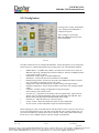
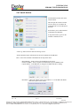
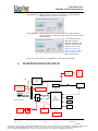
USER MANUAL
MD-0004 TSM Evaluation Board
Temperature Sensor Module (TSM)
Evaluation Board
User Manual
Germany and other countries: LASER COMPONENTS GmbH, Phone: +49 8142 2864 0, Fax: +49 8142 2864 11, [email protected]
Great Britain: LASER COMPONENTS (UK) Ltd., Phone: +44 1245 491 499, Fax: +44 1245 491 801, [email protected]
France: LASER COMPONENTS S.A.S., Phone: +33 1 3959 5225, Fax: +33 1 3959 5350, [email protected]
USER MANUAL
MD-0004 TSM Evaluation Board
Table of Contents
1
2
3
4
5
6
7
Rev. 1.00
Dec./2009
Introduction……………………………………………………………
Host computer requirements…………………………………………..
Installing the software ………………………………………………...
Where to begin with the MD-0004 EVB………………………………
4.1 Evaluation board overview…………………………………….
Where to begin with the MD-0004 PC software………………………
5.1 Temperature Sensor Module overview………………………...
5.2 Running Temperature Sensor Module software……………….
5.3 Main window buttons………………………………………….
5.4 Measuring Temperature Monitor button………………………
5.5 Advanced Features button…………………………………….
5.5.1 Memory button………………………………………….
5.5.2 Config button……………………………………………
5.6 Console button………………………………………………..
3
4
4
5
6
7
7
7
8
9
10
10
11
12
Hardware Block Diagram ……………………………………………. 13,14
Disclaimer ……………………………………………………………. 15
2 of 15
Germany and other countries: LASER COMPONENTS GmbH, Phone: +49 8142 2864 0, Fax: +49 8142 2864 11, [email protected]
Great Britain: LASER COMPONENTS (UK) Ltd., Phone: +44 1245 491 499, Fax: +44 1245 491 801, [email protected]
France: LASER COMPONENTS S.A.S., Phone: +33 1 3959 5225, Fax: +33 1 3959 5350, [email protected]
USER MANUAL
MD-0004 TSM Evaluation Board
1.
Introduction
The Dexter Temperature Sensor Module (TSM), (p/n: MD-0003) consists of the industry
standard Dexter ST-60 with a special embedded signal conditioning ASIC inside the
TO-5 can. Due to the low noise amplifier, 17-bit high resolution ADC and powerful DSP
of the TSM very accurate non-contact temperature measurements can be achieved.
Factory Calibrated object and ambient temperatures is available in RAM of TSM
accessible by the industry standard serial SMBus protocol or via 10-bit PWM (Pulse
Width Modulated) output of the device.
The SMBus allows for multiple zone temperature control – up to 100 sensors can be read
via four common wires.
Traditional IR Detector voltage output is in the microvolt range requiring specialized
electronics to minimize noise, readout electronics, calibration and compensation for
system integration. Using the integrated ASIC with our detectors inside the TO-5 can:
•
•
•
•
•
•
•
•
Electronics is placed at the detector, greatly reducing electrical noise.
Temperature measurements now in digital format.
System integration time and expertise is reduced
Less OEM time to market
Lower system costs
Smaller footprint
Plug and Play
Calibrated output from factory
System Flexibility
The evaluation kit, (p/n: MD-0004) is designed to support the infrared temperature sensor
modules (TSM). The communication between PC and the evaluation board is
accomplished via USB.
The Evaluation Kit contains the following items:
1. FS USB evaluation board (EVB), pre-programmed with USB a
boot loader and demonstration firmware.
2. A standard USB cable for use in communicating with the board.
3. 1 pcs. MD-0003 TSM (single zone 5V)
4. CD-ROM, containing the PC USB HID driver and evaluation software.
5. Quick start guide.
The main purpose of the evaluation kit is to allow customers to configure the TSM for
virtually any application quickly. Customers can quickly evaluate the TSM for
temperature ranges, optics, etc. to find the best configuration to meet their application
needs without the need to design any additional hardware. Once the best configuration is
established, customers can easily configure the TSM for their own use.
The Evaluation Board is based on the Microchip PIC18F4550 which offers a cost
completive hardware designs, low cost development tools and software which could be
an excellent starting point for any hardware design. Dexter offers design services and
could customize the evaluation board to meets your needs as well.
Rev. 1.00
3 of 15
User Manual
Dec./2009
Germany and other countries: LASER COMPONENTS GmbH, Phone: +49 8142 2864 0, Fax: +49 8142 2864 11, [email protected]
Great Britain: LASER COMPONENTS (UK) Ltd., Phone: +44 1245 491 499, Fax: +44 1245 491 801, [email protected]
France: LASER COMPONENTS S.A.S., Phone: +33 1 3959 5225, Fax: +33 1 3959 5350, [email protected]
USER MANUAL
MD-0004 TSM Evaluation Board
2.
Host computer requirements
For the evaluation to function correctly the following hardware and software requirements
must be met:
• PC-compatible system
• An available USB port
• CD-ROM drive (for use with the accompanying CD)
• Microsoft Windows XP or higher.
3.
Installing the software
The evaluation board requires very little effort to install. Most of the work is done by the
installation software. Without the EVB connected to the PC, insert the install CD drive. If auto
run is enabled on your system the software installation should start automatically. If not simply
click on the file “drc_tsm_2_05_setup.exe” on the CD drive to start the process.
After the USB drivers are installed you will be asked to connect the evaluation board to a USB
port on the computer.
To connect the evaluation board:
1. Unpack and unwrap the board, and set it on a non-conductive surface near
the host system. You man elect to place the four rubber feet at each corner of
board at this time.
2. Connect the USB cable (supplied in the kit) to an open USB port on the host
system, and to the USB connector on the board. The LED will shine in BLUE.
3. Check the board connection after software installation. This can be done from
Start/Settings/Control Panel/System/Hardware/Device Manager (Fig. 3.1).
Jungo/tsm_usb and WinDriver
Fig. 3.1
The software will be installed in a separate Dexter Research directory and can be accessed from a
shortcut on desktop “DRC_TSM_02” or Start/Programs/Dexter Research Center/DRC_TSM_02.
Rev. 1.00
4 of 15
User Manual
Dec./2009
Germany and other countries: LASER COMPONENTS GmbH, Phone: +49 8142 2864 0, Fax: +49 8142 2864 11, [email protected]
Great Britain: LASER COMPONENTS (UK) Ltd., Phone: +44 1245 491 499, Fax: +44 1245 491 801, [email protected]
France: LASER COMPONENTS S.A.S., Phone: +33 1 3959 5225, Fax: +33 1 3959 5350, [email protected]
USER MANUAL
MD-0004 TSM Evaluation Board
4.
Where to begin with the MD-0004 EVB
4.1 Evaluation board overview.
9.
1.
10.
2.
5.
6.
7.
12.
3.
4.
8.
11.
13.
FIG 4.1 Top View
14.
FIG 4.2 Bottom View
Rev. 1.00
5 of 15
User Manual
Dec./2009
Germany and other countries: LASER COMPONENTS GmbH, Phone: +49 8142 2864 0, Fax: +49 8142 2864 11, [email protected]
Great Britain: LASER COMPONENTS (UK) Ltd., Phone: +44 1245 491 499, Fax: +44 1245 491 801, [email protected]
France: LASER COMPONENTS S.A.S., Phone: +33 1 3959 5225, Fax: +33 1 3959 5350, [email protected]
USER MANUAL
MD-0004 TSM Evaluation Board
Fig.4.1. shows the top view of the evaluation board. The highlighted areas are:
1.
Test socket for TSM, from supplier: Linear Sales Wells/CTI (p/n 611-1040314)
TSM (p/n: MD-0003) Dexter placed in test socket.
Please note how the device is installed in socket.
White alignment tab on EVB silkscreen and tab on TSM.
2.
VDD test point. Positive voltage applied to TSM module.
3.
Microchip PIC18F4550.
4.
USB Connector
5.
Test points SCL, SDA and GND. Ideal point to monitor SMBus signals with an
Oscilloscope.
6.
RESET button, EVB board and Microchip PIC18F4550 reset.
7.
Status LED. Blue - Board has power, has not communicated with PC software.
Green - TSM has power applied, communicating with PC software.
RED - TSM does not have power applied, it’s OK to change TSM
devices when LED is RED!
NOTE: At NO time should the TSM be inserted or removed if
the LED is GREEN (see Fig. 4.1 item 7). VDD is applied to
the test socket with the GREEN status; damage to the module
may occur.
8.
NEXT and START buttons, available for application program use. START buttons
is used for upgrading Microchip PIC18F4550 firmware.
9.
J1. Extension connector footprint gives provisions to have additional TSM
modules connected to SMBus. This connector is a Molex (p/n 70553-0003) and is
readily available from many suppliers such as Digikey (p/n: WM4902-ND)
Connector SMBus pins:
pin1 - SCL/Vz (arrow )
pin2 - PWM/SDA
pin3 - Vdd
pin4 – Vss / GND
10. Dexter has designed the EVB with some additional general features that could be
used by our customers if needed. One feature of the TSM is the ability for SDA
pin to be use as a thermostat output. Additional hardware could be soldered to the
board which would give a relay output to J5.
Please contact Dexter for further information.
11. The MD-0004 evaluation board receives its power supply only from the USB cable,
Bus-Powered Device. An external power supply source is not needed. However
should you have a need to use the EVB without the USB cable; it is possible to have
an external power source via J4 with additional hardware soldered to the board.
Please contact Dexter for further information.
12. J2. ICD port connector to the Microchip PIC18F4550. Should you elect to develop
your own application software the In Circuit Debugger port of the microprocessor is
available.
13. IC1 8K x 8 serial EEPROM, possible uses data logging, TSM configuration storage.
Additional hardware could be soldered to the board, requires additional software.
Rev. 1.00
6 of 15
User Manual
Dec./2009
Germany and other countries: LASER COMPONENTS GmbH, Phone: +49 8142 2864 0, Fax: +49 8142 2864 11, [email protected]
Great Britain: LASER COMPONENTS (UK) Ltd., Phone: +44 1245 491 499, Fax: +44 1245 491 801, [email protected]
France: LASER COMPONENTS S.A.S., Phone: +33 1 3959 5225, Fax: +33 1 3959 5350, [email protected]
USER MANUAL
MD-0004 TSM Evaluation Board
14. Fig. 4.2 bottom view. If desired you could mount the test socket to the other side of
the EVB. The EVB has been designed to mount in a standard Serpac enclosure
(WM021), available from Digikey SRW021-WA-ND. You have two mounting
option, to the top or bottom covers depending how long you need the test socket to
extend out the enclosure. Placing the test socket on the bottom side of the EVB and
mounting the EVB to the top cover will yield the longest extension of the test socket.
5.
Where to begin with the MD-0004 PC software.
5.1 Temperature Sensor Module overview.
The Temperature Sensor Module software is a Windows-based application designed to be used
with the MD-0004 EVB for evaluating Dexter MD-0003 series infrared non-contact Temperature
sensor modules. The TSM features and performance can be evaluated using the software in
conjunction with the EVB hardware. All basic configurations of MD-0003 are also supported
in a user-friendly application. Device configurations are written in EEPROM of each MD-0003
and then will be the Power on Reset defaults. This provides a way to configure the MD-0003 for
use in target applications.
5.2 Running Temperature Sensor Module software.
Insert a MD-0003 device into the ZIF test socket. Verify that the alignment tab on the MD-0003
matches the silkscreen on the EVB, (see Fig. 4.1 item 1).
At NO time should the TSM be inserted or removed if the LED is GREEN
(see Fig. 4.1 item 7). VDD is applied to the test socket with the GREEN status; damage to the
module may occur.
Launch the software from shortcut on desktop
“DRC_TSM_02” or Start/Programs/Dexter Research
Center/DRC_TSM_02. Startup screen will be appearing on
desktop:
Rev. 1.00
7 of 15
User Manual
Dec./2009
Germany and other countries: LASER COMPONENTS GmbH, Phone: +49 8142 2864 0, Fax: +49 8142 2864 11, [email protected]
Great Britain: LASER COMPONENTS (UK) Ltd., Phone: +44 1245 491 499, Fax: +44 1245 491 801, [email protected]
France: LASER COMPONENTS S.A.S., Phone: +33 1 3959 5225, Fax: +33 1 3959 5350, [email protected]
USER MANUAL
MD-0004 TSM Evaluation Board
After loading, the software will automatically recognize the TSM type,
voltage, SMBus address and open the main screen. The status LED will be
GREEN indicating power is applied and communication is established.
Note: should the LED not turn Green it may be due to a number of items, i.e.
TSM installed incorrectly or not at all. Should this be the case Please press
the reset button on the EVB and re-start the software.
FIG 5.1
5.3 Main window buttons.
Power button and Power Status.
Button turn off power to MD-0003, status LED will turn RED.
Reload button and Power Status.
Re-start system and turns on power to the MD-0003, status will turn GREEN.
Reset button.
Reset the MD-003.
Exit button.
Exit the program.
Rev. 1.00
8 of 15
User Manual
Dec./2009
Germany and other countries: LASER COMPONENTS GmbH, Phone: +49 8142 2864 0, Fax: +49 8142 2864 11, [email protected]
Great Britain: LASER COMPONENTS (UK) Ltd., Phone: +44 1245 491 499, Fax: +44 1245 491 801, [email protected]
France: LASER COMPONENTS S.A.S., Phone: +33 1 3959 5225, Fax: +33 1 3959 5350, [email protected]
USER MANUAL
MD-0004 TSM Evaluation Board
Console button.
Pulls up the Console screen to allow you to monitor USB commands sent
to the EVB. Also allow you to send individual command to the EVB.
Monitor button.
Pulls up the Monitor temperature screen to graph both object and ambient
temperatures.
Advanced button.
Pulls up the Advanced features screen menu. Changing configurations,
reading and writing both EEPROM and RAM can be preformed.
Help button.
Pulls up this User Manual.
5.4 Measuring Temperature Monitor button.
From the Main window click on the Monitor button. This will open the Monitor window screen
and allow you to simply display, plot and capture temperature data. See Fig. 5.2
If PWM mode is selected, the label will changed
to:
“PWM Object Temperature”
That Monitor window screen will allow you to
display, plot and capture PWM temperature data.
Fig. 5.2
Here you can select Celsius or Fahrenheit scale.
Set minimums and maximums for both Object and Ambient Temperatures.
This set the resolution of the graphs and thermometer on the screen only; it has no effect on the
MD-0003 settings.
The slider bar in the middle of the screen “Update Time (ms)” sets the time scale that readings are
taken from the MD-0003. (100 ms to 500 ms.)
Click the “Start” button to begin taking measurements and update graphs.
Clicking the “Save Log” button will allow you to log a date and time stamped readings for both
temperatures to an Excel csv file. Note. You must specify a file of your choice each time you
click the “Save Log”. Data is always appended to this file never erased.
Button will be RED when data log feature is enabled.
Rev. 1.00
9 of 15
User Manual
Dec./2009
Germany and other countries: LASER COMPONENTS GmbH, Phone: +49 8142 2864 0, Fax: +49 8142 2864 11, [email protected]
Great Britain: LASER COMPONENTS (UK) Ltd., Phone: +44 1245 491 499, Fax: +44 1245 491 801, [email protected]
France: LASER COMPONENTS S.A.S., Phone: +33 1 3959 5225, Fax: +33 1 3959 5350, [email protected]
USER MANUAL
MD-0004 TSM Evaluation Board
5.5 Advanced Features button.
From the Main window click on the “Advanced” button. This will give
you three more buttons to choose from: “Config”, “Uploader” and
“Memory”.
Config button will allow you to change several configurations of the
MD-0003 and save them in EEPROM . This will be the new Power On
Reset setting of the MD-0003.
Uploader button will be available in a near future software release.
Allows you to upload new firmware to the EVB.
Memory button. Allows you to view the contents of the EEPROM and
RAM on the MD-0003 in a memory array matrix.
Fig. 5.3
5.5.1 Memory button.
Clicking on the “Memory” button displays the
contents of both the MD-0003 RAM and EEPROM
in a hexadecimal format. “Refresh” button will reread the MD-0003, useful with the RAM display to
show raw sensor data.
RAM addresses of interest
* Ambient sensor data – RAM addr =
* IR data RAM addr =
* Linearized ambient temperature
Ta RAM addr =
* Linearized object temperature
To RAM addr =
0x03h
0x04h
0x06h
0x07h
See Data sheet for information on other address.
Fig. 5.4
Rev. 1.00
10 of 15
User Manual
Dec./2009
Germany and other countries: LASER COMPONENTS GmbH, Phone: +49 8142 2864 0, Fax: +49 8142 2864 11, [email protected]
Great Britain: LASER COMPONENTS (UK) Ltd., Phone: +44 1245 491 499, Fax: +44 1245 491 801, [email protected]
France: LASER COMPONENTS S.A.S., Phone: +33 1 3959 5225, Fax: +33 1 3959 5350, [email protected]
USER MANUAL
MD-0004 TSM Evaluation Board
5.5.2 Config button.
Clicking on the “Config” button allows
you to change how the MD-0003 is
configured to operate.
These settings are stored in the
MD-0003 EEPROM and will be the
Power on Defaults.
Fig 5.5
From this window the user can configure the MD-0003. A short description of every setting field
follows below. For a detailed description of the settings please refer to the MD-0003 datasheet.
*
*
*
*
*
*
*
*
*
*
*
SMBus address - set SMBus slave address. All values between 0 and 7F are valid. All
MD-0003 will accept communication with slave address 0. Therefore in SMBus network
a slave address 0 will be useless.
PWM mode - defines single or extended PWM mode
PWM struct - selects what data will be transmitted via the PWM.
PWM period repetitions - defines how many times each PWM period will be repeated.
Any even number of repetitions from 0 to 62 is valid
PWM period - defines the PWM period. Available settings in drop-down menu.
PWM pin configuration - chooses between NMOS “open drain” and “push pull” PWM
output.
F.I.R filter- Available settings for digital filter in drop-down menu.
Slower settings comes with less noise.
I.I.R filter [%] – drop-down list of available values for impulse limit. 100% passes all
impulse, 50% cuts impulse magnitude in half via the embedded ASIC IIR filter. Note:
that the settling time depends on both FIR and IIR filters settings.
K-Emissivity – adjust the emissivity of the target object.
To max, To min - defines the temperature ranges for object temperature.
Ta man, Ta min - defines temperature ranges for ambient temperature.
Before changing any value you should click the “READ” button to insure values are current. You
can save the configuration to file of your choice by clicking the “Save Config” button. Now you
can restore the TSM to the original values later by clicking “Load Config” button and choosing
the file saved. Click “WRITE” button to send any changes to the MD-0003.
Rev. 1.00
11 of 15
User Manual
Dec./2009
Germany and other countries: LASER COMPONENTS GmbH, Phone: +49 8142 2864 0, Fax: +49 8142 2864 11, [email protected]
Great Britain: LASER COMPONENTS (UK) Ltd., Phone: +44 1245 491 499, Fax: +44 1245 491 801, [email protected]
France: LASER COMPONENTS S.A.S., Phone: +33 1 3959 5225, Fax: +33 1 3959 5350, [email protected]
USER MANUAL
MD-0004 TSM Evaluation Board
5.6 Console button.
From the Main window click on the
Console button.
This will open the Console window
screen to allow you to monitor the
commands sent over the USB port to
the EVB.
It also allows you to send individual
commands to the MD-0003.
A drop down menu is given for the
available command to send.
Fig 5.5
“Clear Log” button will clear data from the log section.
“Send Command” button will transmit the selected command to the MD-0003.
Here is a list of the available commands from the drop down menu.
* Reset Module - Same as Power off and Refresh in one button.
* Switch to SMBus – Issues a request for the MD-0003 to go into SMBus mode.
* Capture PWM – If the MD-0003 is configured for PWM will take a reading.
* Read Ram – enables the address field to select address 0 -31 of the MD-0003 RAM.
Data will be place in the console.
Rev. 1.00
12 of 15
User Manual
Dec./2009
Germany and other countries: LASER COMPONENTS GmbH, Phone: +49 8142 2864 0, Fax: +49 8142 2864 11, [email protected]
Great Britain: LASER COMPONENTS (UK) Ltd., Phone: +44 1245 491 499, Fax: +44 1245 491 801, [email protected]
France: LASER COMPONENTS S.A.S., Phone: +33 1 3959 5225, Fax: +33 1 3959 5350, [email protected]
USER MANUAL
MD-0004 TSM Evaluation Board
* Read EEPROM - enables the address field to select address 0-31 of the MD-0003
EEPROM. Data will be place in the console.
* Write EEPROM - enable the address field to select address 0-31 of the MD-0003
also enables Value 1 and Value 2 fields for data entry to write at the
assigned address.
You are allowed to write
data only to specific
addresses: 0x00 thru 0x06
and 0x0E. Otherwise, the
message “Writes to this
address is not allowed.
Please see user manual for
more information ” will
appear on the console.
* Power Off - Turns off power to the MD-0003, status LED will turn RED.
6.
HARDWARE BLOCK DIAGRAM
J4
7-24
VDC
POWER
SUPPLY
Vdd
PROG. VREG
3 or 5
Vdd
USB
J3
4.8V PS
J1 SMBus
EXTENSION
U4 SMBus Driver
JP2
SMBus
TEST SOCKET
PIC
18F4550
SDA
RESET
SW SW
START
SW
NEXT
SW
J5
RELAY
OUTPUT
IC1 8K X 8
EEPROM
J2
ICD
Rev. 1.00
13 of 15
User Manual
Dec./2009
Germany and other countries: LASER COMPONENTS GmbH, Phone: +49 8142 2864 0, Fax: +49 8142 2864 11, [email protected]
Great Britain: LASER COMPONENTS (UK) Ltd., Phone: +44 1245 491 499, Fax: +44 1245 491 801, [email protected]
France: LASER COMPONENTS S.A.S., Phone: +33 1 3959 5225, Fax: +33 1 3959 5350, [email protected]
USER MANUAL
MD-0004 TSM Evaluation Board
NEXT and START buttons, available for application program use. START buttons is used for upgrading
Microchip PIC18F4550 firmware.
Dexter has designed the EVB with some additional general features (shown in RED) that could be used by
our customers if needed. Additional hardware could be soldered to the board for these features.
Please contact Dexter for further information.
J1.
SMBus extension connector footprint gives provisions to have additional MD-0003 TSM modules
to be connected to SMBus. This connector is a Molex 70553-0003 and is readily available from
Digikey WM4902-ND
Connector SMBus pins: pin1 - SCL/Vz (arrow ) , pin2 - PWM/SDA, pin3 – Vdd ,
pin4 – Vss / GND
J5
Relay output: One feature of the TSM is the ability for SDA pin to be use as a thermostat output.
To use this feature you
would most likely want the external power supply as well for
standalone operation.
Connector pins: pin 1 – Normally Closed, pin2 – Common, pin 3 – Normally Open.
Also the Microprocessor can have the ability to drive the relay with addition software
development.
J4
The MD-0004 evaluation board receives its power supply only from the USB cable, Bus-Powered
Device. External power supply source is not needed. However should you have a need to use
the EVB without the USB cable; it is possible to have
an external power source via J4.
Connector pins: pin 1 & 2 – ground, pin 3 – 7 to 24 VDC.
J2
ICD port connector to the Microchip PIC18F4550. Should you elect to develop your own
application software the
In-Circuit-Debugger port of the microprocessor is available.
Connector pins: pin 1 – Reset, pin 2 – 4.8 VDC, pin 3 – GND, pin 4 – PGD, pin 5 – PGC, pin 6 –
NC.
IC1
8K x 8 serial EEPROM, possible uses standalone data logging, TSM configuration storage.
Requires additional software.
U4
LTC1694-1IS5#TRMPBF SMBus Driver: Should you be using long cables with J1 SMBus
extension it may be required to
use this driver with the additional capacitive load.
Rev. 1.00
14 of 15
User Manual
Dec./2009
Germany and other countries: LASER COMPONENTS GmbH, Phone: +49 8142 2864 0, Fax: +49 8142 2864 11, [email protected]
Great Britain: LASER COMPONENTS (UK) Ltd., Phone: +44 1245 491 499, Fax: +44 1245 491 801, [email protected]
France: LASER COMPONENTS S.A.S., Phone: +33 1 3959 5225, Fax: +33 1 3959 5350, [email protected]
USER MANUAL
MD-0004 TSM Evaluation Board
7.
Disclaimer
Devices sold by Dexter are covered by the warranty and patent
indemnification provisions appearing in its Term of Sale. Dexter makes no
warranty, express, statutory, implied, or by description regarding the
information set forth herein or regarding the freedom of the described
devices from patent infringement. Dexter reserves the right to change
specifications and prices at any time and without notice. Therefore, prior
to designing this product into a system, it is necessary to check with
Dexter for current information. This product is intended for use in normal
commercial applications. Applications requiring extended temperature
range, unusual environmental requirements, or high reliability
applications, such as military, medical life-support or life-sustaining
equipment are specifically not recommended without additional
processing by Dexter for each application.
The information furnished by Dexter is believed to be correct and
accurate. However, Dexter shall not be liable to recipient or any third
party for any damages, including but not limited to personal injury,
property damage, loss of profits, loss of use, interrupt of business or
indirect, special incidental or consequential damages, of any kind, in
connection with or arising out of the furnishing, performance or use of the
technical data herein. No obligation or liability to recipient or any third
party shall arise or flow out of Dexter’ rendering of technical or other
services.
© 2009 Dexter Research Center, Inc. All rights reserved.
www.lasercomponents.com
0/ / V1 / ,) / GUF/ WVPBXVHUPDQXDO.pdf
Germany and other countries: LASER COMPONENTS GmbH, Phone: +49 8142 2864 0, Fax: +49 8142 2864 11, [email protected]
Great Britain: LASER COMPONENTS (UK) Ltd., Phone: +44 1245 491 499, Fax: +44 1245 491 801, [email protected]
France: LASER COMPONENTS S.A.S., Phone: +33 1 3959 5225, Fax: +33 1 3959 5350, [email protected]