1
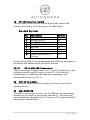
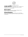
Signature Series
XUSB-2
USB CHANGEOVER SYSTEM
USER MANUAL
V2.5
1 | Page
Table of Contents INTRODUCTION .................................................................................... 3 IMPORTANT SAFETY PRECAUTIONS .................................................... 4 General Safety..................................................................................... 4 Caution ................................................................................................ 5 Power Safety ....................................................................................... 5 Installation Notes ................................................................................ 6 FRONT & REAR PANEL DRAWINGS ...................................................... 7 PANEL DESCRIPTIONS ......................................................................... 8 1 Front Panel USB ............................................................................. 8 2 MIDI Present indicator ................................................................... 8 3 GPI Indicators ................................................................................ 8 4 PC2 (Master Changeover) ............................................................. 8 5 Independent Data Changeover ...................................................... 8 6 Independent KVM Changeover ...................................................... 8
7 Status Display Indicator ................................................................ 8
8 Mains IEC connection ..................................................................... 9 9 Remote Connector ........................................................................ 9 10 VIDEO output A & B ................................................................... 9 11 VIDEO inputs 1 A&B and 2 A&B ................................................. 9 12 USB Console Connectors ............................................................ 9 13/14 Keyboard & Mouse USB Connections ................................. 10 15 GPI Connector .......................................................................... 10 16 Joystick Connector .................................................................. 11 17 MIDI link Indicator ..................................................................... 11 18 GPI Link Indicator...................................................................... 11 19 OPTION Selection Switch .......................................................... 12 20/21 GPI & MIDI USB Connections ............................................... 12 22 MIDI IN Connector ..................................................................... 12 23 MIDI OUTPUTS .......................................................................... 12 Installation and Drivers ..................................................................... 13 Windows Installation ......................................................................... 13 Macintosh OSX Installation ................................................................ 13 Other Notes: ..................................................................................... 14 MIDI Flow Drawing: ............................................................................ 15 2 | Page
INTRODUCTION
Congratulations on purchasing the Autograph XUSB-2 Changeover
system.
The Autograph XUSB-2 is designed for the quick and efficient
changeover of two computer systems incorporating USB Keyboard and
Mouse, Dual Display VGA outputs, MIDI inputs and output and Contact
Closure control.
The system was designed to easily changeover both Macintosh and
Windows based PCs and incorporates dual redundant midi interfaces
and controllers for firing GO, STOP, PREVIOUS and NEXT messages.
Should you experience any problems with your XUSB-2 please contact:
Service Department
Autograph Sound Recording Ltd
2 Spring Place
London NW5 3BA
United Kingdom
Tel. +44 (0)20 7485 4515
Fax. +44 (0)20 7284 1233
Email. [email protected]
3 | Page
IMPORTANT SAFETY PRECAUTIONS
This section contains definitions, warnings, and practical information to
ensure a safe working environment. Please take time to read this
section before installing or using this unit. Please do not
dispose of these instructions.
General Safety
Read
•
•
•
•
•
•
these instructions.
Heed all warnings.
Follow all instructions.
Do not use this apparatus near water.
Do not expose this apparatus to rain or moisture.
Clean only with dry cloth.
Do not block any ventilation openings. Install in accordance with
the manufacturer’s instructions.
• Do not install near any heat sources such as radiators, heat
registers, stoves or other apparatus (including amplifiers) that
produce heat.
4 | Page
There are no user-adjustments, or user-serviceable items, inside
this apparatus.
Do not remove the covers of this apparatus; doing so will
invalidate your warranty.
• Adjustments or alterations to this apparatus may affect the
performance such that safety and/or international compliance
standards may no longer be met.
•
Caution
• Hazardous voltages may be present inside this apparatus.
• Do not operate this apparatus with the covers removed.
• To reduce the risk of electric shock, do not perform any
servicing other than that contained in these installation
instructions unless you are qualified to do so. Refer all servicing
to qualified service personnel and ensure that all power cords are
disconnected when servicing this apparatus.
Power Safety
• This apparatus is fitted with a universal power supply, approved
and certified for operation in this apparatus. There are no userreplaceable fuses.
• Multiple power cords may be supplied with this unit – use only
the power cord appropriate to your local power wiring.
Alternative power cords may be used if rated 2.5A or above and
fitted with a 3-pin IEC320 connector.
• An external over-current protection device is required to protect
the wiring to this apparatus. This protection device must be
installed according to current wiring regulations. In certain
countries this function is supplied by use of a fused plug.
• If an extension power cable or adaptor is used, ensure that the
total power rating of the power cable and/or adaptor is not
exceeded.
• An external disconnect device is required for this apparatus; a
detachable power cord, as fitted to this equipment, is a suitable
disconnect device. The power socket used for this apparatus
should be located nearby and be easily accessible.
• All power cords must be disconnected to isolate this apparatus
completely.
• Unplug this apparatus during an electrical storm or when unused
for long periods of time.
5 | Page
Installation Notes
• When installing this apparatus, either fix it into a standard 19"
rack or place the apparatus on a secure level surface.
• When this apparatus is rack mounted, fit all rack screws. Rack
shelves are recommended for this apparatus.
• Do not operate this apparatus whilst it is covered or boxed in
any way.
• Ensure that no strain is placed on the cables connecting to this
apparatus. Ensure also that such cables are not placed where
they can be stepped on, pulled or tripped over.
6 | Page
FRONT & REAR PANEL DRAWINGS
S ig n ature S eries
STATUS
XUS B- 2 US B COMP UTE R CHANGE OVE R
MID I
PRESE NT
PC 1
J OYS TIC K
GO
STOP
PREV
7
PC2
DATA
4
1
2
3
4
5
6
7
8
8
+5 V
2
6
GPI
NEXT
PC 2
1
KVM
5
+1 2V
PSU INDICATORS
3
9
100-240VAC
10
11
12
OUT A
PC 2A
PC 1A
OUT B
PC 2B
PC 1B
SW 5
MIDI L INK
ON
17
SW
SW
SW
SW
SW
SW
1
2
3
4
7
8
18
(1)
(2)
(4)
(8)
16
JSTICK
PC 1
PC 2
GPI/
MIDI
SW
PC 2
19
15
KEYBAORD/
MOUSE
Se t MID I C h. S witch 1
Se t MID I C h. S witch 2
Se t MID I C h. S witch 3
Se t MID I C h. S witch 4
N ot Use d
R emo te Mom./La tch
SW 6
GPI L IN K
ON
14
GPI
CONSOLE
DIP SW ITC H OPTION S
REMOTE
13
20
PC 1
21
MIDI IN
22
MIDI OUT
23
7 | Page
PANEL DESCRIPTIONS
1
Front Panel USB
These connectors provide easy access to USB connections of PC1 and
PC2 independently of the changeover system. Please note that these
ports are USB1.1 compliant only (12Mbps)
2
MIDI Present indicator
This indicator will illuminate when a midi message is sent to the midi
output of the changeover unit
3
GPI Indicators
These indicators will illuminate when a GPI is activated. GO, STOP,
PREVIOUS and NEXT are accessed from the joystick port, GPI 1-8 from
the GPI port on the rear of the unit.
4
PC2 (Master Changeover)
Activating this button will result in the unit changing all connections
from PC1 to PC2. When this button is illuminated PC2 is selected. This
button changes over KVM, MIDI in and out and GPI connections.
(Subject to status of buttons 5 & 6 see below)
5
Independent Data Changeover
This button allows the changeover of MIDI in and out and GPI control
without switching the KVM facilities. When illuminated MIDI and GPI
control are active from PC2. This button operates in conjunction with
the PC2 Master Changeover button (4).
6
Independent KVM Changeover
This button allows the changeover of Keyboard, Video Displays and
Mouse without switching the MIDI and GPI facilities. When illuminated
KVM is active from PC2. This button operates in conjunction with the
PC2 Master Changeover button (4).
8 | Page
IMPORTANT NOTE:
The Master changeover operates in conjunction with both
KVM and DATA changeover buttons from their current state.
Hence when the Master changeover button is activated both
KVM and DATA changeovers change state from their current
position. Because of this it is possible to get out of sync if
operating the unit remotely. Users should make sure before
a show that when the PC2 button is pressed both DATA and
KVM buttons are illuminated.
7
Status Display Indicator
This LCD display provides information as to the outputs and health
status of the XUSB-2. Each time an input contact is activated the
display registers the MIDI event generated. The display will also
indicate PSU faults and default MIDI channel assignment.
8
Mains IEC connection
The XUSB-2 requires 110Vac – 240Vac at 50Hz main supply.
9
Remote Connector
This four pin XLR connector allows for remote changeover of the
system and an additional latching relay output for changeover of
further connected units.
Pins 1 & 2 provide a momentary contact allowing changeover of
the PC2 master changeover function.
Pins 3 & 4 provide a latching relay output which is closed when
PC2 master changeover is activated.
10
VIDEO output A & B
These 15pin VGA connectors provide dual head VGA outputs from the
KVM switch.
11
VIDEO inputs 1A&B and 2A&B
These 15pin VGA connectors provide dual head VGA inputs to the KVM
switch. VGA from PC1 should be connected to 1A and 1B. PC2
connected to 2A and 2B.
12
USB Console Connectors
These connectors allow connection of a USB mouse and Keyboard that
will be switched between PC1 and PC2. Other USB devices may work
but are not supported at this time.
9 | Page
13/14
Keyboard & Mouse USB Connections
These connections should be made to PC1 and PC2 respectively. They
facilitated the keyboard and mouse control of both PC’s. DATA control
is transported by an additional USB cable and connected to the
DATA/GPI ports (20/21).
15
GPI Connector
This connector allows for additional General Purpose inputs that can be
used to control additional effects. The connector is wired to allow use
of standard Analogue Audio Dtype cables.
Pin
1
2
3
4
5
6
7
8
9
10
11
12
13
Function
GPI 8 (+ve)
NC
GPI 7 (-ve)
GPI 6(+ve)
NC
GPI 5 (-ve)
GPI 4 (+ve)
NC
GPI 3 (-ve)
GPI 2 (+ve)
NC
GPI 1 (-ve)
+5VDC
Pin
14
15
16
17
18
19
20
21
22
23
24
25
Function
GPI 8 (-ve)
GPI 7 (+ve)
NC
GPI 6 (-ve)
GPI 5 (+ve)
NC
GPI 4 (-ve)
GPI 3 (+ve)
NC
GPI 2 (-ve)
GPI 1 (+ve)
NC
10 | P a g e
16
Joystick Connector
This connector accesses the GO, STOP, PREVIOUS and NEXT buttons.
The connector is wired to be compatible with standard 15pin PC
joysticks using SW1-4. Connections are made by connecting and input
to ground. A 5VDC powers rail is supplied for illumination of buttons.
Joystick Pinout:
Pin
1
2
3
4
5
6
7
8
Function
NC
GO
NC
GND
GND
NC
STOP
+5VDC
Pin
9
10
11
12
13
14
15
Function
NC
PREVIOUS
NC
NC
NC
NEXT
NC
17
MIDI link Indicator
When illuminated any midi messages received at the MIDI IN connector
will be passed to the MIDI in of both PC1 and PC2 regardless of Master
Changeover Switch. This facility allows for pseudo tracking via MIDI.
See 19 for more details.
18
GPI Link Indicator
When illuminated any GPI messages received by the unit connector to
be passed to both PC1 and PC2 regardless of Master Changeover
Switch. This facility allows for pseudo tracking via GPI. See 19 for
more details.
11 | P a g e
19
OPTION Selection Switch
This DIP switch can be used to set the default MIDI channel and
common functionality of the box as per the table below:
Standard Key Sets:
Pos
1
2
3
4
5
6
7
8
Description
Set MIDI CH bit 0
Set MIDI CH bit 1
Set MIDI CH bit 2
Set MIDI CH bit 3
MIDI Link
GPI Link
n/a
Remote (momentary or
latching)
Default
On
On
On
On
On
On
Off
On
By default the XUSB-2 is pre-programmed with MIDI note messages on
the default MIDI channel set by the above switches.
20/21
GPI & MIDI USB Connections
These connections should be made to PC1 and PC2 respectively. They
facilitated the MIDI and GPI control of both PCs. KVM control is
transported by an additional USB cable and connected to the
Keyboard/Mouse ports (13/14).
22
MIDI IN Connector
This connector allows for MIDI to be input to either or both PCs as
explained above.
23
MIDI OUTPUTS
The XUSB-2 incorporates a one in four out MIDI thru box permanently
attached to the output of the actively selected PC. All outputs are
opto-isolated and switched from PC1 output to PC2 output with DATA
switching as outlined above.
12 | P a g e
Installation and Drivers
The XUSB-2 includes two internal USB MIDI interfaces. These units are
OEM MIDI Interface that do not require drivers other than those
included with your operating system.
Windows Installation
Drivers are included on most major releases of Windows XP and
Windows 7.Windows Vista is not supported.
Macintosh OSX Installation
Supported Apple Operating Systems: OSX Lion (10.7), OSX Snow
Leopard (10.6) and OSX Leopard (10.5). Previous versions of OSX are
not supported.
13 | P a g e
Other Notes:
Please note that Apple keyboards are not supported by Apple over a
USB extension cable length greater than 1m. Apple keyboards may
work with active USB extensions but no guarantees are made.
14 | P a g e
MIDI OUT #4
MIDI OUT #3
MIDI OUT #2
MIDI OUT #1
MIDI IN
MIDI LINK
SWITCH
MIDI THRU
MIDI THRU
SW 3
A/B MASTER
CHANGOVER
GPI - > MI DI #B
GPI - > MI DI #A
MIDI MERGE #B
MIDI MERGE #A
USB MI DI INTE RFACE # B
USB MI DI INTE RFACE # A
MIDI Flow Drawing:
15 | P a g e