1
DB-889D Multiplexer Board ..................................................................................................................................... 2
1. Function Description.............................................................................................................................................. 2
1.1 Features ..................................................................................................................................................... 2
1.2 Applications .............................................................................................................................................. 2
1.3 Specification.............................................................................................................................................. 2
2. Installing ................................................................................................................................................................ 4
2.1 Layout ....................................................................................................................................................... 4
2.2 Jumper setup.............................................................................................................................................. 5
2.2.1 JP0 ~ JP15 Analog Input R/C Filter............................................................................................. 5
2.2.2 JP16 Analog Output Channel Jumper .......................................................................................... 5
2.2.3 JP19 Internal / External Power selection ..................................................................................... 6
2.2.4
JP18 Local / Remote Gain control ............................................................................................ 6
2.3 Pin Assignment ......................................................................................................................................... 8
3 Analog input & Gain setting ................................................................................................................................... 9
3.1 Input Channel Selection ............................................................................................................................ 9
3.2 Gain Setting............................................................................................................................................. 10
3.3. The Thermocouple Input ........................................................................................................................ 11
3.3.1 Voltage - TO - Temperature Conversion ................................................................................... 12
3.4 CJC Output.............................................................................................................................................. 13
4
Signal Connection.............................................................................................................................................. 14
4.1 Floating Signal Connection ..................................................................................................................... 14
4.2 Non-Floating Signal Source .................................................................................................................... 15
4.3 Cascading DB-889D................................................................................................................................ 16
4.4 Open Thermocouple Detection................................................................................................................ 17
4.5Block Diagram ......................................................................................................................................... 18
5 Programming ........................................................................................................................................................ 19
5.1 Using A-822PGL..................................................................................................................................... 19
5.2 Example Program .................................................................................................................................... 20
6. Calibration ........................................................................................................................................................... 22
6.1 Calibration VR Description..................................................................................................................... 22
6.2 Calibration Steps ..................................................................................................................................... 22
DB-889D User’s Manual (Ver. 1.1, Mar/2010, DMH-003-11)
------- 1
DB-889D Multiplexer Board
1. Function Description
The DB-889D is an expansion multiplexer / amplifier board for use with
A-82X, PCI-1800 series. Each 889D multiplexes 16 differential analog input channels
into one analog input of the DAS board. The high grade instrumentation provides
software programmable gains of 0.5, 1, 5, 10, 50, 100, 500 and 1000.
Thermocouple measurements are handled easily with 889D. The board
includes cold junction sensing and compensation circuitry that provides a scaling of
24.4 mV/°C. Biasing restores are includes for open thermocouples detentions of
voltage measurements or 112 channels of thermocouple measurement.
1.1 Features
z
z
z
z
z
Connects directly to A-82X, PCI-1800 series DAS board or 818 families with
D-sub 37 connectors.
Cold-junction compensation for thermocouples, thermocouple open detection.
Software-programmable instrumentation amplifier
Gain of 0.5, 1, 5, 10, 50, 100, 500, 1000
Daisy chain to ten DB-889D
1.2 Applications
z
z
z
Energy management
Signal conditioning
Analog Multiplexer
1.3 Specification
z
z
z
z
z
Accepts thermocouple type : J, K, T, E, S, R, B
Cold-junction Compensation : +24.4 mV/°C , 0 V at 0 °C
Overvoltage protection : ±30 V Continuous
Common mode voltage : ±10 V max.
Analog output Voltage to A/D card :±10 V
DB-889D User’s Manual (Ver. 1.1, Mar/2010, DMH-003-11)
------- 2
z
z
z
z
z
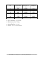
Gain
Common Mode
Rejection
Non linearity %of
FSR
Settling Time
0.5
99dB
±0.0004
23 μs
1
99dB
±0.0004
23 μs
5
114dB
±0.0004
28 μs
10
99dB
±0.0004
28 μs
50
123dB
±0.0004
140 μs
100
123dB
±0.0004
140 μs
500
123dB
±0.0008
1300 μs
1000
123dB
±0.0008
1300 μs
Power requirement : +5 V@120 mA
Dimension :114 mm X 204 mm
Operating temperature : 0~60°C
Storage temperature : -20~80°C
Humility : 5% to 90% non condensing
DB-889D User’s Manual (Ver. 1.1, Mar/2010, DMH-003-11)
------- 3
2. Installing
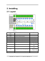
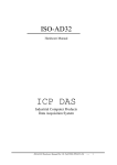
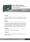
2.1 Layout
CJC Output
VR1
VR2
JP18
JP19
External
Voltage Input
Jumper /Connector
Name
CN1
CN2
CN3
CN4
CN5
CN6, CN8
CN7
JP0~JP15
JP16
JP17
JP18
JP19
Function
Connect to A/D connector of A-82x series
Cascaded to another DB-889D
Connect to D/O connector of A-82x series
Cascaded to another DB-889D
External +5 V power input
Analog input channel 0~ channel 15
CJC signal output connector
Channel 0 ~ channel 15 R/C filter enable
Note
Select by JP19
Short : Filter Enable
Open : Filter Disable
Analog output channel selection
to A-82x series A/D
card
CJC output channel selection
to A-82x series A/D
card
Gain control by on board dip switch or
L : by dip switch
digital output of A-82x series multi-function R : by Digital output
card
Use PC’s +5 V or External +5 V power
DB-889D User’s Manual (Ver. 1.1, Mar/2010, DMH-003-11)
------- 4
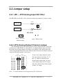
2.2 Jumper setup
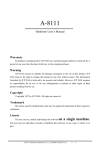
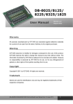
2.2.1 JP0 ~ JP15 Analog Input R/C Filter
The DB-889D provides R/C filter with each analog input channel by jumper setting.
1.2KΩ
Channel 0 High
1uF 50V
Channel 0 Low
1.2KΩ
JP0~JP15
Short : with filter
Default setting
Open : Without filter
2.2.2 JP16 Analog Output Channel Jumper
The DB-889D supports 10 separate jumper to select output channel, This feature
permits up to 10 DB-889D’s be connected to a 10 channel analog input card. Place
the jumper in the output channel according to the channel of the analog input card
selected for that DB-889D board. The following table illustrates the jumper setting of
using the DB-889D with the A-82X series.
JP16
JP17
Analog output CJC output
X
A/D CH0
A/D CH1
A/D CH2
A/D CH3
A/D CH4
A/D CH5
A/D CH6
A/D CH7
A/D CH8
A/D CH9
X
0
1
2
3
4
5
6
7
8
9
If none of the output channel is used,
leave the jumper in position “X”. If
the CJC output is required for the
thermocouple applications, be aware
of the analog output and CJC output
share the connector that analog output
and the CJC output.
Note : “X” means channels are not supported by the A-82Xseries
DB-889D User’s Manual (Ver. 1.1, Mar/2010, DMH-003-11)
------- 5
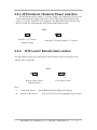
2.2.3 JP19 Internal / External Power selection
The DB-889D requires single +5 V power supply. The connectors CN5 are used
for the external power supply connection. The A-82X series multi-function card
offers +5 V power from the 37 pin connector, The DB-889D can be directly from
the PC I/O bus by connecting the A-82Xseries multi-function card.
JP19
From PC’s +5 V Power
Default Setting
2.2.4
From the CN5 input External +5 V power
JP18 Local / Remote Gain control
The DB-889D provides local and remote control and the selection depends on the
setting of the switch SW1.
JP18
L
R
Remote Gain Control
Default Setting
L
R
Local Gain Control
Note :
“ L “ Local Gain control : from DB-889D on board dip switch setting
“ R “ Remote Gain control :
from A-82X series A/D card digital output control
DB-889D User’s Manual (Ver. 1.1, Mar/2010, DMH-003-11)
------- 6
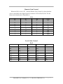
Remote Gain Control
When the JP18 is set to “R” , it means Remote Gain Control is selected and the
gain is controlled by the digital signal of connector CN3 bit D4, D5, D6. The bit
pattern and related gain is illustrated as:
CN3
D6
D5
D4
Gain
0
0
0
0.5
0
0
1
1
0
1
0
5
0
1
1
10
1
0
0
50
1
0
1
100
1
1
0
500
1
1
1
1000
Local Gain Control
Sw1
1
2
3
4
Gain
ON
ON
ON
OFF
0.5
ON
ON
OFF
OFF
1
ON
OFF
ON
OFF
5
ON
OFF
OFF
OFF
10
OFF
ON
ON
OFF
50
OFF
ON
OFF
OFF
100
OFF
OFF
ON
OFF
500
OFF
OFF
OFF
OFF
1000
DB-889D User’s Manual (Ver. 1.1, Mar/2010, DMH-003-11)
------- 7
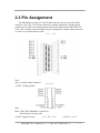
2.3 Pin Assignment
The DB-889D provides two 37pin D-Sub connector & two 20-pin flat cable
connector. The CN1, CN2 D-sub connector is analog output link to analog input
connector of A-82X series multi-function card & cascaded another DB-889D. The
CN3, CN4 is digital control multiplex & gain setting link to digital output connector
of A-82x series multi-function card .
CN1
Note:
AO_n : analog output channel n
A. GND : Analog ground
,
CN2
CN3 , CN4
Note
DOn : DO0~DO3 Multiplexer control bit.
DO4~DO6 Gain control bit
D. GND
: Digital Ground
+5 V : PC’s +5 V
+12V PC’s +12 V
DB-889D User’s Manual (Ver. 1.1, Mar/2010, DMH-003-11)
------- 8
3 Analog input & Gain setting
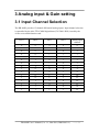
3.1 Input Channel Selection
The DB-990D provides 15 channel differential analog inputs. Input channel selection
is controlled by the 4 bit TTL/CMOS digital data (CN3 DO0~DO3) issued by the
A-82x series multi-function card .
DO 3
DO 2
DO 1
DO 0
Analog input
channel
0
0
0
0
0
0
0
0
1
1
0
0
1
0
2
0
0
1
1
3
0
1
0
0
4
0
1
0
1
5
0
1
1
0
6
0
1
1
1
7
1
0
0
0
8
1
0
0
1
9
1
0
1
0
10
1
0
1
1
11
1
1
0
0
12
1
1
0
1
13
1
1
1
0
14
1
1
1
1
15
DB-889D User’s Manual (Ver. 1.1, Mar/2010, DMH-003-11)
------- 9
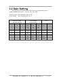
3.2 Gain Setting
The high grade instrumentation provides software programmable gains or
switch selectable gain of 0.5 1, 5, 10, 50, 100 , 500, 1000.
Software Setting : JP18 should be place on “R”
Switch Setting : JP18 should be place on “L”
Software Setting
(Remote control)
Switch Setting
(Local Control)
Gain
DO 6
DO 5
DO 4
SW1-3
SW1-2
SW1-1
0
0
0
ON
ON
ON
0.5
0
0
1
ON
ON
OFF
1
0
1
0
ON
OFF
ON
5
0
1
1
ON
OFF
OFF
10
1
0
0
OFF
ON
ON
50
1
0
1
OFF
ON
OFF
100
1
1
0
OFF
OFF
ON
500
1
1
1
OFF
OFF
OFF
1000
DB-889D User’s Manual (Ver. 1.1, Mar/2010, DMH-003-11)
------- 10
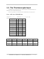
3.3. The Thermocouple Input
The DB-889D can accept thermocouple sensor to measure temperature. The DB-889D should be set to
different gain value if use different thermocouple type.
If you are using A82XPGL series multi-function bard to linked DB-889D you have got the gain as :
Gain = A82X Gain X DB-889D Gain
A821PGL Gain = 1 , 2 , 4 , 8
DB-889D Gain = 0.5 , 1 , 5 , 10 , 50 , 100 , 1000
Examples
A-82XPGL Series
DB-889D
Gain
1
X
1
1
2
X
1
2
4
X
1
4
1
X
5
5
1
X
10
10
1
X
100
100
2
X
100
200
4
X
100
400
1
X
500
500
1
X
1000
1000
:
X
:
:
:
X
:
:
Thermocouple type & suitable gain
TYPE E
TYPE J
TYPE K
TYPE R
TYPE S
TYPE T
-270°C to 1000°C
-210°C to 760
-270°C to 1370°C
0°C to 1760°C
0°C to 1760°C
-270°C to 400°C
-9.835 mV to
-8.096 mV to
-6.458 mV to
0 mV to
0 mV to
-6.258 mV to
76.358 mV
42.922 mV
54.807 mV
21.006 mV
18.612 mV
20.869 mV
Gain=50
Gain=100
Gain=50
Gain=200
Gain=200
Gain=200
DB-889D User’s Manual (Ver. 1.1, Mar/2010, DMH-003-11)
------- 11
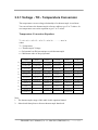
3.3.1 Voltage - TO - Temperature Conversion
The temperature-versus-voltage relationship of a thermocouple is not linear.
You can reference the thermocouple reference tables to get V to T values. Or
use temperature conversion equation to get V to T values.
Temperature Conversion Equation:
T = a0 + a1 x + a2 x^2 + a3 x^3 + a4 x^4 + …….. + an x^n
where
T = Temperature
x = Thermocouple Voltage
a = Polynomial coefficients unique to each thermocouple
n = Maximum order of the polynomial
TYPE E
TYPE J
a0 -100°C to 1000°C 0°C to 760°C
TYPE K
0°C to 1370°C
TYPE R
TYPE S
TYPE T
0°C to 1000°C 0°C to 1750°C -160°C to 400°C
a1
0.104967248
-0.048868252
0.226584602
0.263632917
0.927763167
0.100860910
a2
17189.45282
19873.14503
24152.10900
179075.491
169526.5150
25727.94369
a3
-282639.0850
-218614.5353
67233.4248
-48840341.37
-31568363.94
-767345.8295
a4
12695339.5
11569199.78
2210340.682
1.90002E+10
8990730663
78025595.81
a5
-448703084.6
-264917531.4
-860963914.9
-4.82704E+12
-1.63565E+12
-9247486589
a6
1.10866E+10
2018441314
4.835606E+10
7.62091E+14
1.88027E+14
6.97688E+11
a7
-1.76807E+11
-1.18452E+12
-7.20026E+16
-1.37241E+16
-2.66192E+13
a8
1.71842E+12
1.38690E+13
3.71496E+18
6.17501E+17
3.94078E+14
a9
-9.19278E+12
-6.33708E+13
-8.03104E+19
-1.56105E+19
2.06132E+13
1.69535E+20
Note :
1. The thermocouple range of this table is this equation limited.
2. Other detail data please reference thermocouple data book.
DB-889D User’s Manual (Ver. 1.1, Mar/2010, DMH-003-11)
------- 12
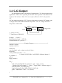
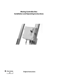
3.4 CJC Output
The DB-889D provides Cold-Junction Compensation (CJC) for the thermocouple
applications. If the CJC is required, place the JP17 in the position of the channel to be
used as a CJC reference. If the CJC is not required, Place the JP17 in the position
“X” .
CJC has output on connector CN7. Using a voltage meter measures CN7 which exists
a voltage related to the DB-889D board temperature. The CJC voltage transfers to
temperature with formula:
CN7
T(°C) = V*1000/24.4
A.GND
Voltage meter
CJC output
+
-
V: Voltage of CN7
T: Temperature of DB-889D
Example : (Turbo C )
Multi-Function Card : A-822PGL
If the DB-889D JP17 place on “7” .
/*====================Example Program ===================*/
#include <stdio.h>
#include “A822.h>
main(void)
{int ad_channel , gain , trigger_mode, poll_data ;
float temp;
A822_Initialize(0,0x220, -1, -1);
/* Initials A-822PGL Ref. A-822PGH/L Software Manual */
ad_channel=7;
gain=0;
trigger_mode=1;
for(;;)
{
A822_AD_SetChGainMode(ad_channel , gain , trigger_mode );
/* Setting A822 A/D channel =7 , Gain=1 , Trigger mode = Software trigger */
poll_data=A822_AD_PollingVar();
temp=(float)(((poll_data-2048)*5/2048)*1000/24.4);
prinf(“ Temperature = %4.1f °C \n”, temp);
}
}
DB-889D User’s Manual (Ver. 1.1, Mar/2010, DMH-003-11)
------- 13
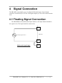
4
Signal Connection
The DB-889D can multiplex up to 16 channel differential inputs. Input channel
selection is controlled by a CN3 D4~ D6 digital output by A-82x series multi-function
card.
4.1 Floating Signal Connection
The DB-889D has only differential input channels, each input channel should be
two signal wires. The input should be connected as:
CH0HI
Floating Signal Source
DB-889D
CH0LO
Differential signal input
A.GND
DB-889D User’s Manual (Ver. 1.1, Mar/2010, DMH-003-11)
------- 14
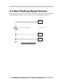
4.2 Non-Floating Signal Source
Some the signal source has one side connect to a local ground. The signal ground with
DB-889D ground will not be same voltage level. The input should be show as:
CH0HI
Common mode Signal Source
DB-889D
CH0LO
A.GND
Common mode signal input
DB-889D User’s Manual (Ver. 1.1, Mar/2010, DMH-003-11)
------- 15
4.3 Cascading DB-889D
DB-889D #1
37Pin Cable
A-82X series A/D card
20 Pin Flat Cable
1.
A821PGH/L
2.
A-822PGH/L
3.
A-823PGH/L
DB-889D #2
4.
A-826PGH/L
5.
PCI-1800PGH/L
Note : PCI-1802 should be via DB-1825
connect to DB-889D
A-82X series
DB-889D
JP16
A/D Channel 0
DB-889D #1
0
A/D Channel 1
DB-889D #2
1
A/D Channel 2
DB-889D #3
2
A/D Channel 3
DB-889D #4
3
A/D Channel n
DB-889D #n
n
A/D Channel 9
DB-889D #10
9
DB-889D #3
DB-889D #n
Up to 10 Board
Note : Each DB-889D JP17 place on “X”
DB-889D User’s Manual (Ver. 1.1, Mar/2010, DMH-003-11)
------- 16
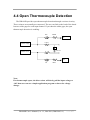
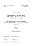
4.4 Open Thermocouple Detection
The DB-889D provides open thermocouple detection through a resistor circuitry.
These resisters are normally not connected. The user can find on the back of the board
has two solder gaps for each input channel. If you short the solder gaps, the open
thermocouple detection is enabling.
HJ0
100MΩ
-15V
1.2KΩ
Channel 0 High
1uF 50V
Channel 0 Low
1.2KΩ
GND
LJ0
10KΩ
Note :
If a thermocouple opens, the bias resistor will slowly pull the input voltage to
-10V then user can use a simple application program to detect the voltage
change.
DB-889D User’s Manual (Ver. 1.1, Mar/2010, DMH-003-11)
------- 17
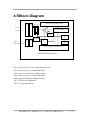
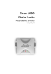
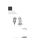
4.5Block Diagram
CN1
CN2
CN8 Connector with R/C filter
JP16 JP17
A-82X
AMP
Analog input
16 channel Multiplexer
VR1
CJC
Dip Switch
CN3
A-82X
CN4
Control
Logic
VR2
D/O control signal
CN6 Connector with R/C filter
DB-889D Block Diagram
CN1: connect to A-82x series multi-function card
CN2: connect to CN1 of another DB-889D
CN3: connect to A-82x series digital output
CN4: connect to CN3 of another DB-889D
AMP: programmable gain amplifier (PGA).
VR1 : PGA off-set adjustment.
VR2 : CJC gain adjustment
DB-889D User’s Manual (Ver. 1.1, Mar/2010, DMH-003-11)
------- 18
5 Programming
The A-82x series multi-function card can support up to 160 channel by cascading 10
DB-889D’s. And this is very easy to programming DB-889D.
5.1 Using A-822PGL
This section will use A-822PGL to link DB-889D.
The major step are listed below:
Step 1 Hardware installing.
1.
Turn off power of computer.
2.
Plug in A-822PGL then connect 37 pin cable & 20 pin flat cable to CN1 and CN3
of DB-889D.
3.
4.
5.
6.
7.
setup DB-889D (Ref. Jumper setting section of DB-889D. the example program
use default setup )
Connected your signal wiring.
Turn on your computer power.
Installing A-822PGL C library.
Now your ready to programming.
Step 2. Software programming ( C Language)
1.
Using A-822 library function to initial A-822PGL
2.
Setup A-822PGL : Bipolar mode , Gain = 1 , Analog input channel = 0 , Trigger
mode = Polling mode.
3.
Send digital output of A-822PGL data to control DB-889D
D0~D3 : DB-889D channel selection , D4~D6 : DB-889D Gain setting
4.
Reading A-822PGL analog input data
5.
Conversion data to voltage or temperature
Note :
The A-82X series programming step same as A822PGL
DB-889D User’s Manual (Ver. 1.1, Mar/2010, DMH-003-11)
------- 19
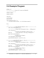
5.2 Example Program
DEMO_01.C
/* ============== Using A-822 / connect one DB-889D
=================*/
#include <stdio.h>
#include “A822.h”
main(void)
{int data1,data2;
float vol1,vol2;
A822_Initialize(0,0x220,-1,-1);
/* A-822 Base address in 0x220
ref. A-822 Software manual */
for(;;)
{
/*===============reading DB-889D Channel 0 , Gain =1 =============*/
A822_AD_SetChGainMode(0,0,1);
/* Setup A-822 A/D channel 0, Gain = 1 , Polling mode */
A822_DO(0x0010);
/* Send D/O data to DB-889D , Channel 0, Gain=1 */
delay(10);
/* delay about 43u sec . Ref. Page 3 Settling time */
data1=A822_AD_PollingVar();
/* Reading A-822 A/D data */
vol1=(float)((data1-2048)*5/2048);
printf(“DB-889D channel 0= %6.4f V\n”,vol1);
/*===========reading DB-889D Channel 1 , Gain=10 ===============*/
A822_AD_SetChGainMode(0,0,1);
/* Setup A-822 A/D channel 0, Gain = 1 , Polling mode */
A822_DO(0x0021);
/* Send D/O data to DB-889D , Channel 1, Gain=10 */
delay(10);
/* delay about 43u sec , Ref. Page 3 Setting time*/
data2=A822_AD_PollingVar();
/* Reading A-822 A/D data */
vol2=(float)((data2-2048)*0.5/2048);
printf(“DB-889D channel 1= %6.4f V\n”,vol2);
}
DB-889D User’s Manual (Ver. 1.1, Mar/2010, DMH-003-11)
------- 20
}
DB-889D User’s Manual (Ver. 1.1, Mar/2010, DMH-003-11)
------- 21
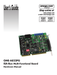
6. Calibration
The DB-889D is calibrated to its best of operation. For environment with large
vibration, recalibration is recommended. Before calibrating the DB-889D, user should
take care the following issue:
z
z
z
One 6 digital voltage meter.
One temperature meter
One A-82x series multifunction card
6.1 Calibration VR Description
There are two VRs on the DB-889D .
VR Num.
Description
VR1
Amplifier Offset adjustment
VR2
CJC Gain adjustment
6.2 Calibration Steps
1.
2.
3.
4.
5.
6.
7.
8.
9.
10.
11.
Turn off computer power.
Connect A-822PGL ( Or Any A-82x series multi-function card ) to DB-889D.
Setup DB-889D to default setting
Short CH0HI to CH0LO to A.GND of DB889D.
Connect probe of voltage meter to CN7 ( CJC output :+ , A.GND : - ).
Turn on computer power
Waiting about 5 minute ( warn up ).
Run Calibration program of DB-889D.
Close the probe of temperature meter to DB-889D them reading temperature
value.
adjust VR1 until the screen value = 0;
adjust VR2 until voltage meter reading value = temperature value X 2.44 mV
DB-889D User’s Manual (Ver. 1.1, Mar/2010, DMH-003-11)
------- 22