1
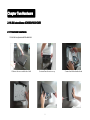
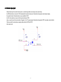
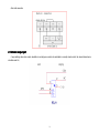
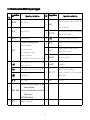
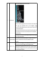
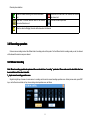
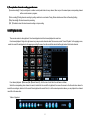
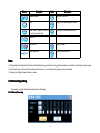
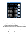
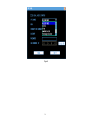
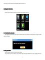
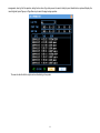
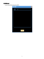
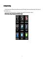
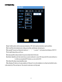
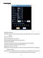
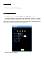
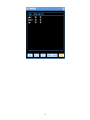
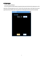
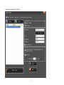
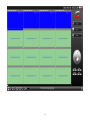
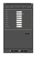
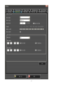
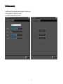
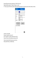
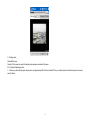
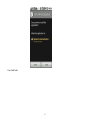
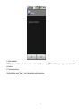
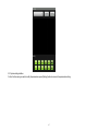
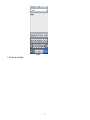
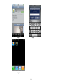
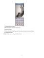
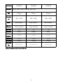
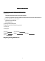
H.264 Standalone DVR
4CH/8CH/16CH
USER MANUAL v1.00
1
INDEX
............................................................................................................................ 5
Chapter one Products Introduce
Introduce............................................................................................................................
1.1 Technical Parameter......................................................................................................................................................................................................................... 5
1.2 Performance..................................................................................................................................................................................................................................... 6
.............................................................................................................................................. 8
Chapter Two Hardware
Hardware..............................................................................................................................................
2.1H.264 standalone 4CH/8CH/16CH DVR..........................................................................................................................................................................................8
...................................................................................................................... 14
Chapter Three Products Introduce
Introduce......................................................................................................................
3.2 Powering On.................................................................................................................................................................................................................................. 18
3.2.1 Boot-strap......................................................................................................................................................................................................................... 18
3.2.2 Shutdown..........................................................................................................................................................................................................................18
3.3 Enter System Menu........................................................................................................................................................................................................................ 19
3.4 Power-down and Revert................................................................................................................................................................................................................. 20
3.5 Preview.......................................................................................................................................................................................................................................... 20
3.6 Recording operation....................................................................................................................................................................................................................... 21
3.6.1 Manual recording.............................................................................................................................................................................................................21
3.6.2 Playback video.................................................................................................................................................................................................................22
3.6.3 Recording setting.............................................................................................................................................................................................................23
3.6.4 Video Detection................................................................................................................................................................................................................26
3.6.5 Alarm setting and alarm linkage recording.................................................................................................................................................................. 30
3.7 Backup recording file.....................................................................................................................................................................................................................31
3.7.1 Detection device.............................................................................................................................................................................................................. 31
3.7.2 Backup operation.............................................................................................................................................................................................................32
3.8 How to control PTZ....................................................................................................................................................................................................................... 33
3.8.1 Method of connection......................................................................................................................................................................................................33
3.8.2 The method of PTZ control operation...........................................................................................................................................................................33
3.8.3 PTZ control....................................................................................................................................................................................................................... 34
3.9 3G module......................................................................................................................................................................................................................................35
.................................................................................................................. 38
Chapter Four Menu Operation Guide
Guide..................................................................................................................
2
4.1 Menu Navigation............................................................................................................................................................................................................................38
4.2 Menu Operation............................................................................................................................................................................................................................. 41
4.2.1 Play Back..........................................................................................................................................................................................................................41
4.2.2 System Information......................................................................................................................................................................................................... 42
4.2.3 System Setting.................................................................................................................................................................................................................46
4.2.4 Record Control.................................................................................................................................................................................................................53
4.2.5 Hard Disk Drive Management....................................................................................................................................................................................... 53
4.2.6 Alarm Control................................................................................................................................................................................................................... 54
4.2.7 Advanced Options........................................................................................................................................................................................................... 54
4.2.8 File Backup.......................................................................................................................................................................................................................60
Chapter Five IE Preview
..........................................................................................................................................
61
Preview..........................................................................................................................................
..........................................................................................................................................61
5.1 logging on interface....................................................................................................................................................................................................................... 61
5.1.1 To input the IP address................................................................................................................................................................................................... 61
5.2 System Settings.............................................................................................................................................................................................................................. 64
5.3 State control................................................................................................................................................................................................................................... 67
.......................................................................................................
70
.......................................................................................................70
Chapter Six Instruction for mobile monitor
monitor.......................................................................................................
6.1. DVR Setup.................................................................................................................................................................................................................................... 70
6.2. Mobile phone setup....................................................................................................................................................................................................................... 70
........................................................................................
97
........................................................................................97
Chapter Seven FAQ (Frequently Asked Questions)
Questions)........................................................................................
3
�...
Power
This DVR select the adaptor is DC12V; please make sure the power supply voltage before use the machine.
If long time do not use the machine, please turn off the power of DVR machine, and let the electric plug away from power socket;
�...
safety
This DVR only for indoor use, as for prevent short circuit or electric danger, please do not let the DVR in the raining or humid area.
In case any solid or liquid inside the case of DVR, please turn off the power immediately, and ask the qualified technician check it before reboot
the DVR;
The DVR is the precision machine, there is nothing for repair by customers themselves in it, when it break down, please ask the qualified
technician to check and repair, or contact with the agents of it.
�...
Installation
Please keep the DVR in level for installation;
Pay attention to equipment ground;
For the first time to install the DVR, please make sure if the hard disk drive install or not;
Prevent to open the case and change the hard disk drive in electrified;
Propose to select the performance of hard disk drive will be 7200 rotating speed person second;
Please select the appropriate installation site, so let the air can be free flow inside the DVR, prevent the machine overheating;
Please do not install the DVR nearby the radiator, air chute etc. heat source, or where the direct sunlight, too much dust, or mechanical vibration
or attack;
4
Chapter one Products Introduce
1.1 Technical Parameter
Compression standard
iInput
H.264 baseline [email protected]
Composite 1.0Vp-p/75Ω,BNC×4/ BNC×8/ BNC×16
Video output
Composite 1.0Vp-p/75Ω,BNC×1, VGA×1
Resolution
Preview
Bit rate
Preview/ recording
4ch 100fps(PAL), 120fps(NTSC
8ch 200fps(PAL), 240fps(NTSC)
16ch 400F/S(PAL), 480F/S(NTSC)
Audio input
-8dB~22k,RCAx4(4ch), RCAx4(4ch)
Audio output
-8dB~92dB,RCAx1
Audio decode
ADPCM
Alarm input
Input low level alarm, user setting normal open or normal close, Varies according to
the model
Alarm output
1ch output or 2ch output;Varies according to the model
Recording mode
Manual recording, timing recording , motion detection recording and external alarm
recording
Simplex/duplex/ triplex
triplex(recording, playback , LAN transmission)
LAN
RJ45(10M/100M self-adapting)
PTZ control
Yes
Communication
RS485×1,USB2.0×1
USB
USB mouse control
Hard disk drive
1or2x SATA(2TB or above)
D1 720×576(PAL)
,720×480(NTSC)
CIF 352×288(PAL),320×240(NTSC)
Recording D1 720×576(PAL)
,720×480(NTSC)
CIF 352×288(PAL),320×240(NTSC)
5
Remote control unit
Yes
Dimension
Main board size : 220mm x 112mm
Power supply
AC110-230V
1.2 Performance
Real-time
monitoring
Turn-by-turn analog video output and VGA Storage
interface, according to TV monitor or VGA function
monitor to live view in 1/4/8/9/16 or more
video channel to monitoring the recording
streaming and the record file capacity in
every hours every channel, to presentation
the status of video channel, recording,
dynamic detection, video loss, monitoring
lock-up. You can view the system log in
local DVR.
Internal 1or2 SATA interface, MAX 2TB hard disk
drive, the file of hard disk drive include cover mode
circulation recording and none cyclical recording,
the storage data to use the proprietary format, can not
falsify the data, make sure the data safety.
Compressi
on format
Video compression format:: H.264
Support 8ch video and audio signal, video
and audio maintaining stability in
synchronous.
Through USB interface to backup. ( for example USB
Backup
function
drive and mobile hard disk drive etc.)
The video file can be downloaded by Client software
through LAN to laptop hard disk drive.
6
Recording
and
* Multiplex, to achieve real time recording Network
to be independent at the same time to Operation
* through network to real time remote monitoring;
* PTZ control
playback
function
single channel playback, research and function
backwards, network monitoring, network
search download etc.
* Multiple recording mode: Manual,
* recording research and real time playback;
* system setting parameter modify and the system
software upgrade;
* remote monitoring alarm process and view the
normal, alarm, linkage, dynamic detection
recording etc. turn-by-turn pre-recording
function.
* Can playback the record file in DVR
through network, to achieve quick-search
the recording file and recording type,
multiple playback type: SLOW, Fast
system log message;
* to use embedded TCP/IP protocol and Embedded
Operation System, can access the DVR through client
software program bundle in the package;
* Management Model: use enhancement user
management, password mode to make sure the valid
user to login the system, flexible convenient and fast
Forward, Backwards, step Forward.
Display the exact time of event occurred
while recording file playback.
to set the different permission user requirement.
Alarm
linkage
function
8ch alarm input ( alarm event mode can be Comset normal open or normal close
munication
selection), and turn-by-turn video loss
port
alarm, dynamic detection alarm, the alarm
device may be smoke detection censer,
temperature detector, IR detector.
Possess 4ch relay switch alarm output,
flexible convenient and fast to achieve
alarm linkage and lighting control at site.
They’re possess protective circuit in Alarm
input and alarm output port, make sure the
device not to damaged.
* Possess specific interface, achieve alarm input and
PTZ control;
* possess a standard Ethernet interface, achieve the
network remote monitoring.
PTZ
control
* Support PTZ decoder through RS485 Intelligent
communicate
operation
* scalable multiple decoder protocol, easy
to achieve to control the pan driver and
* mouse operation function;
* In menu for same setting and to process shortcut
copy operation
7
speed dome camera function.
8
Chapter Two Hardware
2.1H.264 standalone 4CH/8CH/16CH DVR
2.1.1 Hard disk Installation
For the first use, please install the hard disk
1 Remove the screws on both sides of shell
○
2 extracted from the next cover up
○
9
3 connect hard disk and mother board
○
4 fix the screw of hard disk
○
5 close cover
○
6 install the screws on both sides of shell
○
2.1.2 Rear panel
4CH
Item
Interface
1
VIDEO IN
4ch video input
2
AUDIO IN
4ch audio input
3
V-OUT
1ch video output
4
A-OUT
1ch audio output
5
VGA
VGA monitor
6
NET
RJ45 for internet
7
USB/ MOUSE
8
ON/OFF
Power supply switcher
9
DC-12V
Power adaptor port
10
Description
First USB for backup or upgrade system of DVR; Second
USB for mouse
ALARM IN:1 2 3 4 alarm input port
RS-485:A, B
ALARM OUT: N1 alarm output port, every channel connect
every two channel OUT, COM port is for GND;
8CH
10
GND、OUT、COM;
Item
Interface
1
VIDEO IN
8ch video input
2
AUDIO IN
4ch audio input
3
V-OUT
1ch video output
4
A-OUT
1ch audio output
5
VGA
VGA monitor
6
NET
RJ45
7
USB/ MOUSE
8
ON/OFF
Power supply switcher
9
DC-12V
Power adaptor port
10
Description
First USB for backup or upgrade system of DVR; Second
USB for mouse
ALARM IN:IN1-IN4 alarm input port
RS-485:A , B
ALARM OUT: N1 N2 alarm output port, every channel connect
every two channel OUT, COM port is for GND;
16CH
11
GND、OUT、COM;
Item
Interface
1
VIDEO IN
16ch video input
2
AUDIO IN
4ch audio input
3
V-OUT
1ch video output
4
A-OUT
1ch audio output
5
VGA
VGA monitor
6
NET
RJ45 for internet
7
USB
First USB for backup or upgrade system of DVR;Second
8
ON/OFF
Power supply switcher
9
DC-12V
Power adaptor port
10
Description
ALARM IN:4CH
USB for mouse
alarm input port
RS-485:A, B
ALARM OUT: N1 N2 for alarm output port, every channel connect
is for GND;
12
C and O;COM port
2.1.3 Alarm input port
8chanel alarm input, the mode of alarm input is no restriction (possible is normal open also normal close);
the GND alarm detector connect to COM under parallel connection (the power of alarm detector supply by external power supply;
the ground terminal of alarm detector join-up in parallel with DVR;
the NC of alarm detector connect with the input end (alarm) of DVR;
when you want to reset the remote alarm of triggered , the +12V power supply of alarm detector supply by DVR, for example, smoke detector.
When you select the external power supply, please share the GND with DVR;
Alarm input circuit:
13
Alarm inlet connection:
2.1.4 Alarm output port
4 way switching value alarm output, selectable in normally open contact, also selectable in normally closed contact, the external alarm device
should be need Vcc;
14
Chapter Three Products Introduce
Operation instruction
3.1Operation
15
3.1.1 Remote control AND Front panel keypad
S/N
pad Name
KEYpad
Operating instruction
【OK】
9
【SWITCH】
Switch capital letter/small letter/symbol
input on soft keyboard
Access main menu
10
【
Switching of 1/4/8/9 Preview mode
Exit operation or enter upper menu
Close soft keyboard
Close current window
Exit from current control
Return to last menu
Exit from PTZ control under preview state
11
【PTZ】
Access/exit from PTZ control under preview
state
12
【+/-】
Volume or number increase/reduction
Select item of the list
13
【SEARCH】
Search for playback
14
【ALARM】
Alarm reset
15
【0~9 10+】
Digital input Corresponding;
Channel is magnified in full screen under
preview state
Play / Pause
16
【FN】
Short cut
17
18
Power ON/OFF
2
【DEV】
Select DVR1,2,3,…
3
【MENU】
【ESC】
【
】
Slow playback,1/2 × , 1/4 × , 1/8 × and
single frame play
【
】
Fast playback, 2×,4× and 8× playback
【
】
Playback stop
5
】
Operating instruction
8
【POWER】
【
Keypad Name
This button is used as “enter”and“ok” key
in
most circumstances
1
4
S/N
6
【▲.▼.⊳. �】
Four-way to move the focal point in main
menu, up and down
to move in the normal window, to control pan
driver to move in
the PTZ control windows
7
【REC】
To mode of recording
16
】
3.1.2 How to use mouse of DVR (for right hand mouse)
To any function menu icon click the mouse left key into the menu
To run the control point out operation
Change again select frame or motion detection piece mode
Click the assemble frame popping to pull down the list
1
Left key single click
In the input frame, can select digit, character, lowercase, block letter, left click mouse on
the keyboard of character input, that’s. ← say move back, _ say blank
17
Right click mouse, popping the shortcut menu, as follows;
2
Right click mouse
。
while life view monitoring, popping short cut menu: multi picture mode, recording mode,
PTZ control, clear alarm,enable listen into, video adjustment, recording
control,TV/VGA Switch display,main menu etc short cut manner. Thereinto, the PTZ
control and video adjustment
manner are set the video channel where cursor locates at that time, before setting, if the
mode if multi picture, then the system can automatically switch to the correspondence
single channel picture.
In the title bar, if you click right key of mouse wherever outside of the edit box and the
button, it will close current window.
3
Double click left button
To run the ActiveX Control ActiveX special operation, For example, double click the
certain item of record listed file, then the system will playback the segment
record video.
Depress the left key and dragging the mouse, banding select Motion detection area,
depress right key of mouse and Dragging, cancel the banding select area.
4
Dragging the mouse
Dragging playback ProgressBar back and forth to dolly moves, to achieve the playback
position adjustment. Dragging the audio and video regulation parameter bar dolly moves,
to achieve the parameter adjustment.
18
3.2 Powering On
.1 Boot-strap
3.2
3.2.1
If【POWER】pilot lamp off, please follow the operation step by step:
First step: if the power does not plug into, please plug into the power, then the DVR-4108 begin to start, by now, if the DVR-4108 still inactive, to
enter the next step;
Second step: turn on the power supply of the DVR-4108 at the back panel, DVR begins to start.
If【POWER】pilot lamp to offer RED, press the 【POWER】key, DVR-4108 begins to start.
The video output mode of DVR-4108’s the default setting is multi picture channel mode after starting the DVR-4108, if the time of start the
DVR-4108 is in the Timing Recording Setting, the DVR-4108 will automatically to start the Timing Recording function, the corresponding channel’s
recording pilot lamp will be light, the DVR-4108 is normal operation.
If you do not install the hard disk drive in the DVR-4108 before turn on the power, after Login the system, the system will call attention to as follows;
3.2.2 Shutdown
� There are two safety mode for Shutdown
A. Pressing the POWER key in 3 second, according to Shutdown warning to stop the all running of DVR-4108, then you can turn off the power key
behind the DVR case.
19
B. Enter【Main Menu】→【Log Out】select【Shutdown system】.
� Abnormal shutdown
Through the rear panel to shutdown
During the DVR-4108 running, directly to turn off the power through the rear panel power switch, please avoid as much as possible to do it.
(specially while the DVR recording).
Directly to pull up the power cable of DVR-4108
While the DVR-4108 running, directly to pull up the power cable of DVR-4108, please avoid as much as possible to do it. (specially while the DVR
recording).
Caution: In some area, the power supply is irregularity, it will cause the DVR-4108 working not normal-operation, the DVR-4108 will be damaged in
serious. In this surroundings, suggest select the stabilized voltage supply.
3.3 Enter System Menu
How to enter the Menu Mode
� Press【MENU】key, enter main menu
� Click【Mouse right key】enter shortcut menu
� Click【T-RSH】shortcut, enter playback menu
� click【REC】shortcut, enter manual recording operation menu
� Click【PTZ】shortcut, enter PTZ control operation menu
20
Introductions: you should input the user name and password when you login DVR system, the default user name is “admin”, and the password is
“666666”.
There are three default user, that’s “admin, user, default”, and the user and default’s password is “123456”. The user name “admin” is the top
authority user in default, and the “default” is the low authority user in default, only for monitoring, playback, backup etc. authority.
Password security: you can try 5 times in 30 minutes, otherwise, the user name will be locked;
Remark: for safety, suggest to change the password after use the DVR-4108, put the additional user name and change the default user name, for
the use setting please refer to Menu operation----User management.
Concerning the input method: except the front panel and remote control unit can be input, you also can input the character in the InputBox, single
left click the mouse, the system will dropping the software keyboard.
3.4 Power-down and Revert
When the DVR run under Recording, Timing recording, Alarm Recording, if the power of DVR to be turn off or be forced to turn off, and turn on the
power again, DVR will automatically save the recording before turn off, and automatically to revert the operating condition before turn off to work on.
3.5 Preview
After log in system of DVR, system will automatically directly enter the preview mode
In the preview picture, you can see the overprint date, time, channel name, if the date and time is not correct show on the picture, re setting the
date. There is a alarm input mode icon. (the meaning of every kind of icon as following table)
21
Channel picture attention
1
When that channel recording, this mark will be showed
on it
2
When there is a motion detection alarm in that channel, 4
this mark will be show on it
5
3
When there is a video loss in that channel, this mark will
be showed on it
The mark of alarm input mode
When the video be Dodging, this mark will be showed on that channel
3.6 Recording operation
Customer can according to select the different kind of recording mode in this system. For the different kind of recording mode you set, the channel
will be showed the mark on everyone channel.
3.6.1 Manual recording
” permission. Please make sure the hard disk drive has
Note: Manual recording operational requirement the user should have “recording
recording”
been installed and it has been formatted
formatted..
Input manual recording operation menu
1)Input
Single click right key of mouse or In main menu=> recording control can into manual recording operation menu. Under preview mode, press REC
key or on the Remote controller unit key into recording control operation menu, as follows:
22
2) The explanation of manual recording operation menu
【manual recording】 Priority level highest, no matter currently what status of every channel, after carry out the manual press, corresponding channel
will be record common in progress;
【Auto recording】Setting channel recording by setting condition to record under Timing, Motion detection and Alarm in Recording Setting;
【Stop Recording】All video channel stop recording;
【All 】Possible to select all video channel recording or stop recording.
3.6
3.6..2 Playback video
There are two mode in video playback: One channel playback and four channel playback at same time.
One channel playback: Single click right mouse key in anyone video channel under Preview menu, select “Record Playback” in the popping menu,
search the record file and playback in the popping recording file menu, then the record that selected will be play backed in that video channel.
Four channel playback:【Main menu】�【Record Search】, click the icon of mark file in the red frame as follows;
Select the corresponding video channel to search, double click the record file to playback; then move the mouse to the Second video channel to
search the record again, double click the record file and playback the record file in it; to do the same step mention above, you can playback four channel
record file at the same time.
Toolbar of playback
23
Button
Description
Button
Description
Playback/pause
Open the record file
stop
Single video channel playback mode
From quick playback, slow to
normal play back mode
Four video channel playback mode
Slow, fast
Sound on/off
Hide the toolbar
Voice adjustment
Close the window menu
Note:
1) During playback the Playback Tool will show the file playback speed, channel, timing, playback speed etc. information in the Playback control panel;
2) Can’t same time to select the Fast forward operation function in over 2 channel, only progress in anyone channel;
3) Can drag the Playback Speed toolbar by mouse;
3.6
3.6..3 Recording setting
Two mode in recording: Manual Recording and Auto Recording
3.6.3.1 Manual Recording
24
Click 【Main Menu】�【Recording Control】, as above diagram,select anyone channel to recording, the White color means the recording function
enable,Black color means disable;
Also can select “All” mark,if select it, then the recording function enable in all channel, click confirm.
3.6.3.2 Auto Recording
The Auto Recording function includes;
External Alarm Recording: Please find the details of it in 3.6.5 in this menu(Alarm setting and Alarm linkage Recording)
Normal Schedule Recoding: The default setting is 24hours non-stop recording after the First time to boot the DVR system. Login the menu, can set
the Timing of DVR to record continually, that’s recording in the timing that you select in sometime area, find the details
setting in 【Main Menu】�【System Setting】�【Recording Setting】
Motion Detection Recording: Please find the details of it in 3.6.4 in this menu(Motion Detection)
25
Including the time slice of setting Normal Recording, Motion Detection Recording, Alarm Recording;
【Channel】/【Recording Schedule】Drop-down menu, select the corresponding channel Number/Week to set, select “ALL” can set the all channel
function enable in onetime;
【Alarm Recording】Can record 3-5seonds video before the alarm event to occur(the timing depends on the capacity of video streaming);
【Time Slice】The means the recording mode of that channel currently in some time, “■” anti-display setting normal, alarm recording mode, can
select single or multi in it, four time slice for setting selectable. Under some recording mode and the time in different time slice, you
can duplicate to set, the time setting range is 00:00-24:00, after set the channel parameter, please press the save key to save the
setting in the system.
Shortcut setting
1) Duplicate the same setting from one channel to another channel, for example, select channel one, after recording mode setting, click the copy
icon into the others.
2) User should save the setting one by one after channel setting.
26
3.6
3.6..4 Video Detection
Note:
1) Select【Main Menu】�【System Setting】�【Video Detection】 to enter the setting menu;
2) During motion mode switch, there is not None Area and Sensitivity setting in video loss and video cover detection;
3) When there is a motion detection event in one channel, the symbol of motion detection will show in the channel;
4) No need to use FN function key when you drag the motion detection area by mouse, click the right key of mouse to save the setting before exit, the
user press the SAVE to confirm before exit the Motion Detection menu.
27
VIDEO Detection
1)VIDEO
To excessive the video picture, when the system detect the motion event that the sensitivity fit for the preinstall, then motion detection alarm on.
Method of Operation:
【Channel】 Select what you want to set the motion detection function channel area;
【Alarm Mode】Select the motion detection mode: Motion Detection;
【 Recording Channel 】 Select what you want to need the channel to recording ( can repeat to select ), when there is a alarm, the system can
automatically to start the recording in that channel, At the same time, should set the motion detection recording mode in
【Recording Setting】, set the Auto Recording mode in 【Recording Control】;
【Clear Time Delay】That means, when the motion event finish, the recording will be stopped in extending time, the time in Second, the range from
5-300;
【Channel Cruise】Anti-display■Setting when there is an alarm event, it will automatically to switch the single channel video that set the recording
channel before. The switching time setting in the【Local Display】 setting;
【Region】Move the mouse to setting, press ENTER key to enter; the set region divide into 192 (16x12) region;
The border blocks representatives where the cursor locates, the green region is dynamic detection security region, achromatic color is open
28
security region. Press <Fn> key to set on security or not, set the on security press direction key to move the green border grid to set the dynamic
detection region, after setting, press <ENTER> confirm to exit dynamic detection region setting, if press < ESC> exit dynamic detection region then it
will cannel the all security setting. When you exit the dynamic detection menu, must to press save key to save the setting, otherwise, the dynamic
detection security function is disabling.
【Sensitivity】You can set them to: Highest, high, normal, low, lowest;
【Alarm output】When there is dynamic detection event, to start the linkage alarm output port to the external alarm device;
【Screen presentation】Invert signify show happen dynamic detection, it will show the prompting message;
【Time Slice】Can set the alarm output situation in two time slice, please do not set the repeat in the time slice setting, alarm output and prompting
message option invert the corresponding channel option selector button, that’s there is an alarm to start alarm output or prompting
message in the selected time slice.
Video Loss
2)Video
When there is a video loss situation, select【Alarm Output】and【Screen presentation】 that’s the video loss message shows on the local screen.
Method of Operation:
【Channel】Select that channel what you want to set the dynamic detection region;
【Alarm Mode】Select detection mode: Video Loss;
【Recording Channel】That means it needs to record video (multi selectable) when there is a video loss, when there is an alarm, the system will
automatic start to record in that channel. At the meantime, select the dynamic detection recording in the【Recording Setting】,
29
select the automatic recording in【Recording Control】;
【Clear Time delay】That means after the dynamic, the recording will be stopped in some time delay, the time unit is in second, the range is 10-300;
【Channel Switcher】When there is an alarm in Invert setting, the single video channel will switch in that selected to start record channel, the time of
channel switcher setting in【Local Display】setting;
【Alarm Output】When there is a video loss, start the linkage alarm output port to the external alarm device;
【Time Slice】Can set alarm output situation in two time slice, the time slice setting allow in repeat, the system according to the selected operational
context to press or operate in the current time slice. That is if there is a prompting message in the current time slice One, no in time
slice Two, then there is a prompting message in this time slice. Alarm output and prompting message selection invert, that’s there is an
alarm output or prompting message in the selected time slice.
Video Cover
3)Video
When some body malice to cover the lens of camera, or due to the lighting caused etc. lead to the video output display in monochrome attic, that is
unable to monitor scene video. Through the Video Cover alarm setting, it can effective to prevent phenomenon to happen, select【Alarm Output】and
【Prompting Message】.
Method of Operation:
【Channel】Select that channel you want to set the Dynamic Detection region;
【Alarm Mode】Select detection mode: Cover Detection;
【Recording Channel】That means it needs to record video (multi selectable) when there is a video loss, when there is an alarm, the system will
automatic start to record in that channel. At the meantime, select the dynamic detection recording in the【Recording Setting】,
select the automatic recording in【Recording Control】;
【Clear Delay】That means after the dynamic, the recording will be stopped in some time delay, the time unit is in second, the range is 10-300;
【Channel Switcher】When there is an alarm in Invert setting, the single video channel will switch in that selected to start record channel, the time of
channel switcher setting in【Local Display】setting;
【Alarm Output】When there is a video loss, start the linkage alarm output port to the external alarm device;
【Time Slice】Can set alarm output situation in two time slice, the time slice setting allow in repeat, the system according to the selected operational
context to press or operate in the current time slice. That is if there is a prompting message in the current time slice One, no in time
slice Two, then there is a prompting message in this time slice. Alarm output and prompting message selection invert, that’s there is an
alarm output or prompting message in the selected time slice.
Explanation:
30
1.During copy the setting what you did before, only copy the same setting what you wan to set. That’s say, the setting of video loss can not be ed to
paste to video cover after copied(For example: the cover detection of Channel One only be copied to the others channel’s cover detection, can not be
copied into the other mode), by parity of reasoning.
2. In the default operation process, according to the different setting of channel and detection mode, only to detect the mode of current channel in
default operation. For example, default operation in cover detection menu, only set cover detection in default, the operation can not to set the other
detection mode.
3.Caution: you can select the short cut copy function to set the same channel, but in video detection setting, that can not be copy to use the
dynamic detection copy function region parameter, because there is not same in everyone channel video.
3.6
3.6..5 Alarm setting and alarm linkage recording
Details setting in【Main Menu】�【System Setting】�【Alarm setting】
User should separate to save after to everyone channel setting.
【Alarm Input】Select corresponding alarm channel Number;
31
【Device Mode】Select normal open/normal close (voltage output);
【Channel Switcher】Invert■setting when there is an alarm event, due to select start to record the channel progress to single channel switching
display, select the switching setting time mode in the menu【Output Mode】;
【Recording channel】Select the require recording channel( repeat selectable), when there is an alarm event, the system will automatic to start that
channel to record. At the same time, select the dynamic detection recording in【Recording Setting】, select the automatic
recording in【Recording Control】;
【Alarm Output】Alarm linkage output port(repeat selectable),when there is an alarm event, can be linked the corresponding alarm output device.
【Clear Time Delay 】Select corresponding time delay(5-300, the unit in second),after clear the external alarm, system automatic to delay the
corresponding time, then close the alarm and linkage output;
【Prompting message】Show the prompting alarm message in the local DVR;
【Time Slice】Can set alarm output situation in two time slice, the time slice setting allow in repeat, the system according to the selected operational
context to press or operate in the current time slice. That is if there is a prompting message in the current time slice One, no in time
slice Two, then there is a prompting message in this time slice. Alarm output and prompting message selection invert, that’s there is an
alarm output or prompting message in the selected time slice.
3.7 Backup recording file
The backup of Standalone DVR can be by SATA DVD-R/RW, USB DVD-R/RW, USB storage device, download through LAN etc.
First to introduce the USB storage backup operation, please find the details of it in the LAN client operation download backup through LAN.
3.7
.1 Detection device
3.7.1
The backup device are USB DVD-RW, pen drive, mobile hard disk drive etc. devices, it will show the detection device in the file backup device. And
show the total storage file capacity.
【Detection】Click Detection button, if use the USB backup device in the USB port, then show the display device mode, partition in the above list box;
【Remove】Click the Remove button, the installed mobile USB device will be uninstalled, the information of device will be clear in the list box;
32
.2 Backup operation
3.7
3.7.2
【Add】Click the backup dialog box ”Accession ” button, popping “Recording Searching” . Searching the DVR record file according the time, channel,
searching mode etc. information, searching information show in the dialog box. One or more file to add selection in one time, after process,
the file will be showed in the “file backup” diagram dialog box that the file need to backup.
【Delete】You can delete the one or more file in the “file backup” dialog box file list frame, the operation will be delete the content list only, and do not
delete file;
【Clear】Clear the content list in the dialog box;
【Backup】To backup the all file in the dialog box into the appointed backup device, before the backup operation, please confirm the selected backup
device, and it has enough space to backup.
During the backup operation, you can process to the other operation, after the backup furnish, it will automatic to show
the successful information
information.. The backup task cannot be canceled
canceled..
You can check the backup video file in your personal computer, the format of video file is: channel name + year/month/day/hour/minute/second.lvf
33
3.8 How to control PTZ
3.8.1 Method of connection
1)connect RS-485 port of speed dome camera with he DVR PTZ port ;
2)connect the video cable of speed dome with the DVR video input jet ;
3)turn on the power of speed dome after connected mention above;
3.8.2 The method of PTZ control operation
1) the current video channel must switch to that channel camera will be controlled in the video channel;
2) finish setting the ID of speed dome;
3) confirm if it is correct or not from the cable A,B of speed dome to the cable A,B of DVR,(please see the details of in chapter II: 2.1.2)
4) process corresponding setting in DVR menu, details setting in 【Main Menu】�【System Setting】�【PTZ Setting】.
34
【Channel】Select the connect channel of camera;
【Protocol type】Select the corresponding brand model protocol of speed dome camera;
【Address】Setting the corresponding ID of speed dome camera;
Caution; the ID and protocol setting of DVR should fit for the speed dome camera, other wise, you can not control the speed dome camera
through RS-485 of DVR;
【Baud rate】Select the corresponding baud rate of speed dome camera, can control to the corresponding channel PTZ and camera, the default
setting is 9600;
【Data bit】Default is 8;
【Stop bit】Default is 1;
【examination】Default is None;
【Flow-control】Default is None;
PTZ setting should be saved in everyone channel after setting.
3.8.3 PTZ control
To control the 【direction】,【speed】,【aperture】,【focus】,【Iris】,【cruise control】,【cruising setting】,【scan boundary】,【back light Compensation】,
【auto scan】Of PTZ, coordinate with the direct key during setting;
There are two different kind of control interface in PTZ control, in preview mode, click right key of mouse in everyone channel, the shortcut menu will
popping the “PTZ Control” selection as follows.
【Assist On/Off】Can call the user-defined assist function, for example, lighting, windshield wiper etc;
【Preset setting】Preset point setting;
【Call preset】Call the preset point setting;
The function call display menu interface in【Main menu】�【PTZ control】 as follows;
The setting of pan driver step length through the inferior level slid bard of direction key to adjust. Major for neck rein operation, the step length is
more and more longer then the rotational speed follows;
Direct to single click the key of
,
of zoom, focus, IRIS, adjustment for zoom, definition, illumination.
35
The rotation of pan driver can supports 4 direction, there is Up, Down, Left and Right.
The 【Boundary Scan】setting move to control the JIONT of speed dome, left margin setting, horizontal shifting move to the another point, to set the
right margin.
【Auto Scan】after the running Auto scan, can control the it running in Auto Scan in the left and right boundary of speed dome camera.
3.9 3G module
or this function, first enter “3G DIAL ”(MAIN MENU→ADVANCE→3G DIAL) and then start to setup,as Figure1, the interface shows as Figure 2,
Figure 3.
“3G DIAL” have two modes with automatic and manual dialing, the operation follows as below.
Figure1
1. Automatic Dialing
Select the Automatic Dialing in the interface of Figure 2, fill the right information according to the operator where the 3G card belongs to and the 3G
referred guide, It includes IPS names, AP, dial-telephone, ID and password, the interface shows as Figure 3 (some IPS once be chosen, the other
36
relative information has been already done, so you needn’t fill any more, click “SAVE” directly). Then click “Save” directly. After having detected the 3G
signal when DVR start, the system will dial up automatically.
Figure2
2. Manual Dialing
In the interface of figure 2, users would fill the right information in the menu bar as same as
Automatic dialing and click “SAVE”. Then click “Dial-up” after saving successfully (The referred information would be saved still after the DVR
restart, but you should click “Dial-up” again).
In these two modes, if the dial-up want success, first you should make sure that the 3G card is available. Since the 3G signal has been existed, the
related menu bar will show the correct IP address; if failed, system will popup a window to show the wrong information.
37
Figure3
38
Chapter Four Menu Operation Guide
4.1 Menu Navigation
Main Menu
First level
menu
Option remarks
To achieve the function of record file searching and playback, the listing of
searching according to the record mode, channel, timing, display the result situation
in listing, process the playback after the record file select ed.
R-Normal recording, A-Alarm recording, M-Motion detection recording
Play Back
Hard disk
drive
Log
System
information
version
Online user
System
setup
Encoding
setting
System Setting
The interface position of SATA hard disk drive, the total capacity, surplus capacity,
the start-stop recording time information of all hard disk drive and everyone.
Mode: read-write drive, read-only drive etc.
Display the log of system important event, and record the log appointed.
Display the property of system hardware, software version and the day of release
Check the information of on line user
System time, preservation mode of record, the DVR model etc. basic parameter
Encode mode, bit rate, quality parameter etc. setting of audio and video,
Recording
setting
The timing setting includes the timing recording, dynamic detection, external alarm
event;
The duration of everyday timing operation in one week( recording, receive external
alarm event, running dynamic detection), the every mode can be set in two different
kind of duration in everyday
PTZ setting
Parameter setting of PTZ
39
Network
setting
Alarm
setting
The parameter setting of network ID, video data transmission protocol etc. and the
function of PPPoE, DDNS.
The parameter setting of for external alarm output and record response.
Video
detection
The dynamic detection parameter setting of sensitivity, region and pre-processing
(alarm output and start recording) , video loss, blank screen detection etc.
Local
display
The parameter setting of output menu and monitoring switching
Caution: after the menu modify output attribute, the presentation will be go to take
effect after system reboot.
On or Off the channel recording
Recording
Control
The operation of Hard disk drive management, clear the data in hard disk drive;
Attention: modify property of hard disk drive, it will take a effect after the system
reboot.
Hard disk drive
management
PTZ Advanced Features
Alarm input, output function
Alarm control
User
account
The user management function
Exception
Advanced
System
upgrade
The item need to system maintenance setting, upgrade function
40
Options
Output
adjustment
Revert
default
Adjust the output parameter of VGA
According to select revert all or part of it into default delivery setting
Attention: user account setting is not the recovery function
Detection backup device
Listed the detected device, display the name, mode and capacity etc.
Backup the record file into the backup device.
File backup
Log off, turn off, reboot system operation
Turn off system
41
4.2 Menu Operation
Main menu interface introductions
The main menu function includes recording search, system information, system setting, recording control, hard disk drive management, alarm
control, Advanced Options, file backup, turn off system.
Explanation:
The all-following sub-menu setting should to take effect after save, otherwise, the setting invalid.
The checkbox be filled means that someone function sleeted, not be filled that means no select some one function.
4.2.1 Play Back
To achieve the recording search and playback function, the listed searching according to the recording mode(all, normal, alarm, dynamic detection),
42
channel, timing to search, please see the result listed table( please see chapter III 3.6.2)
4.2.2 System Information
Sub-system menu: hard disk drive information, log information, version information, on-line user.
4.2.2.1 Hard Disk Drive information
Display SATA hard disk drive interface status, mode, all hard disk drive and everyone hard disk drive interface position, total capacity, available
capacity etc. information.
4.2.2.2 Log Information
Show the system log, convenience of customers to see the login log.
The log message type can be divided into system operation, setting operation, data management, alarm event, recording operation, user
43
management, clear log file, file operation, setting the time slice of log what you want to search, directly to press Search button, system will display the
record log listed, press Page up or Page Down key to search the page turning operation.
The user who has the limits to rights can clear the date log in the system.
44
4.2.2.3 Version Information
Display the system hardware characteristic, software version and release date code etc information.
45
4.2.2.4 Online user
To see the LAN user information who log in the local DVR.
46
4.2.3 System Setting
Sub-Menu:【System Setup】,【Encoding Setting】,【Recording Setting】,【PTZ Setting】,【Network Setting】,【Alarm Setting】,【Video Detection】,
【Local Display】etc. menu.
Please see the details of【Recording Setting】,【PTZ Setting】,【Alarm Setting】,【Video Detection】in Chapter III.
Attention: System setting must login by who hold the limits to rights
47
4.2.3.1 System Setup
【System Time】Be used for modify the current system date and time of DVR, click the right hand side button to save the modification;
【Date Format】Select the date display format, including year/month/date, month/date/year, date/month/year etc;
【Date separator】There are three different kind of selection in it, “— ” “ / ” “.” , if you select “.” , then the system time will display as: 2008.07.20
【Time Format】Including 24 hours and 12 hours;
【Recording Length】Can setting the duration of everyone recording file, default is 60 minutes;
【Identification Number】Be used for the situation that use one remote controller unit to over one DVR, only press the ID of remote controller unit on
it and the same corresponding DVR ID number, so, you can control the DVR;
【Video System】According to setup setting different system;
【Menu Standing by】Possible to set the menu standby-time 20-60second, 0 is not set the standby-time, if you Setup time, behind that time slice,
system automatic log off the current login user, if the user wants to operate menu, must to login again.
48
4.2.3.2 Encoding Setting
【Channel】Select channel Number;
【Encoding Type】Select “audio & video” then the recording file will be audio and video composite streaming, select “video” the streaming will be
video only;
【Encoding Size】CIF/Half D1/D1;
【Streaming Control】Including fixed bit rate, dynamic bit rate;
【Encoding Quality】6level video quality, they’re best, well, good, middle, worst, bad;
【Code Rate】Max 1 Mbps, Min64Kbps;
Caution: when the code rate control set into dynamic bit rate, the default setting will be the upper limit in the 【Code Rate】;
【IP Gap】From 0 to 255 adjustment to continues, 0 means full I frame pattern encoding;
【Frame Rate】1fps to 25fps in PAL, or 30fps UNCAL;
【Default】Channel is the First channel, encoding type is video, resolution is CIF, streaming control is dynamic code rate, the code rate upper limit is
512Kbps, frame rate is 25fps;
【Region Override】Invert, press the appear setting button and cover type selection, enter the corresponding channel video, user can select any size
area to cover by mouse, anyone can not monitor or playback the area that has been set the cover area before;
49
【Time Overlap】and【Character Overlap】Overlap everyone channel encoding, there are time and channel title overlap, can set if you want to overlap
where the time and channel overlap in the encoding data, single click the setting button, drag the time title
or channel title to good place. If overlapped, the time and channel message will be display on video file
when you playback the record file.
4.2.3.3 Recording Setting
Please find the details of it at Chapter III 3.6 (Recording Operation).
4.2.3.4 PTZ Setting
Please find the details of it at Chapter III 3.8 (PTZ Control Operation).
4.2.3.5 Network Setting
50
【IP Address 】 Press Up/Down/Left/Right key or input the corresponding numeric key to modify the IP address parameter value ( the IP address
setting can be set in this setting item), then set the subnet mask and Default Gateway of the corresponding IP address;
【Server Port】The general default is 7777, according to set the port under the user actual-need (remark: the server port 7777 preserve for UDP port,
please do not configure for the others);
【HTTP Port】General default is 80;
【Start Multicast】Start Multicast network transmission modes, turn on the multicast function nee to set the corresponding multicast address and port;
【Start DDNS】Via DDNS server, it compatible with DYNDNS.ORG, NO-IP.ORG, support www.3322.org DDNS server;
【Start PPPoE】Input ISP ( Internet Service Provider) user name and password provided by PPPoE, reboot the system after save the setting. After
boot the DVR, system will automatic to setup the PPPoE network connection, after successful setting, the IP of 【IP address】will be
modify automatically achieved the Internet dynamic IP address;
Operation: After PPPoE dialup successfully, please check the IP on【IP Address】, achieved the currently IP of DVR, then access the IP of DVR
through client.
51
4.2.3.6 Alarm Setting
Set alarm output port, Invert ■ that means selected, press confirm button to save and exit, press cancel button to cancel and exit, manual to turn
On/Off the corresponding alarm output port.
4.2.3.7 Video Deteciton
Please find the details of it at Chapter III 3.6.4 (Video Detection).
4.2.3.8 Local Display
52
【Channel Name】Press the channel name modify button, enter the channel name menu, can modify the name of channel, during modify the channel
name in local, the WEB or client do not update the new channel name immediately follow the local DVR modify, need to open the
channel name to upgrade the channel name in WEB or client;
【Window Color】According to the user favor to choose the background color and transparency;
【Transparency】There are three type for select: 25%, 50%, 75%;
【Time Overlap】
、【Channel Name Overlap】Status invert■marking, display the system date time and channel number in the monitoring video;
【Start Switching】Invert signify Start Switching function;
【Switching Gap】Setting switching time, switching blanking time is 5-120 second, the switching video including single video and quad video. The 8
selected video frame signify the channel of switching in the single frame, the two selected switching video frame has four frame
video in one bar (1, 2,3,4 channel is First page, the others is Second page), the single and quad video frame can be switched at
the same time, if you selected 1,2,5,7 in single video frame, at the same time, sleeted quad video frame in the Second page, when
there is a switching, it will First to display in spacing 1,3,5,7, then display the quad video frame in the Second page.
53
4.2.4 Record Control
Please find the details of it at Chapter III 3.6.3 (Recording Setting).
4.2.5 Hard Disk Drive Management
Host hard disk drive setting management, enter 【Main Menu】�【Advanced Options】�【Hard disk drive management】.
The following pictures show the properties current hard disk drive: type, status, total capacity, capacity, available capacity. The red cross mark
means there is not hard disk drive be connected to DVR, the yellow cross mark means there is a connected hard disk drive but it should be formatted,
green hook means the hard disk drive can be used. Operate to format the all data on the hard disk drive, Press Execution button to operation, after
finish, press confirm button and the system will presentation should reboot the system for confirm.
After formatted hard disk drive, the file format is ext3.
54
4.2.6 Alarm Control
Please find the details of it at Chapter III 3.6.5 (Alarm Setting and Alarm Linkage Recording).
4.2.7 Advanced Options
The Advanced Options including menu: hard disk drive management, user account, system maintenance, output regulation, Revert Default.
4.2.7.1 User Account
Management user account properties
The user name max character size is 8 character, the beginning and the end of the string is bland invalid, it can not be blank in the middle. The
legal character: letter, numeral, not allowed to use the other character symbol.
The user quantity max is 20pcs, the user can be added in user-defined, but the name of user can not be same repeat, the everyone user name can
be modified permission by admin, the other user name can permission modify the password themselves;
Modify password: permission to modify the password of user name, select user name, input the new password in the new password and confirm
the new password again. Press save button for confirm the password modification. The password can be set from 1-8pcs, the
password can not be in blank at the beginning and the end, the middle allow in blank. The legal character: letter, numeral, not
allowed to use the other character symbol.
Caution: The current password means the user logins
55
56
Add user: add user name in group and set the user permission control. Enter add user menu interface, input user name and password, select it
which group does belongs to, and select is it multiplex user or not. Multiplex means that user can be used at same time, the user name can be used
by some client at same time, “■” means selected.
57
There are 3 user name admin,usrer,default in initialization, admin is the highest permission in delivery default setting, and the password is
666666,and the default user name is low permission user under delivery default setting, only can monitoring, playback, backup permission etc.
Default:this user is for system internal use, can not be deleted. When there locates “no user login” situation at local DVR, system will automatic to
log in under this default user name. user can according to modify the permission of this user account, accomplish the operation of some no need to
login. The other user who have account permission can modify the permission of Default, that is, user can use this function when there is not user login
DVR, For example, if you want to view some video channel when there is not user login, you can select the permission in that corresponding video
channel in Default account, scalable setting the others permission setting.
4.2.7.2 Exception
58
4.2.7.3 System Upgrade
Set the item can Autonomous Maintenance.
User can set the automatic reboot system themselves, the automatic reboot system need to set the date and time, (please make sure to set the
enable function in DVR where longtime no body to look for it. Finally to click the confirm button, otherwise, it will be canceled. User can copy the
upgrade firmware software into USB drive, click the “start upgrade” button, after finished upgrade successful, the system will reboot automatically.
59
4.2.7.4 Output Adjustment
Adjust the VGA output area, brightness, chromaticity and resolution.
60
4.2.7.5 Revert Default
System revert to the default setting status of Delivery (according to revert the details sleeted in the menu.
Attention: Menu color, language, date time format, video system, IP address, user account etc. can not be reverted.
4.2.8 File Backup
Please see the details of it at Chapter III 3.7 (The Backup Operation of Recording File ).
61
Chapter Five IE Preview
5.1 logging on interface
5.1.1 To input the IP address
62
Pretermission IP address is 192.168.0.19
63
64
5.2 System Settings
Point
, As the picture ,You can set up language directory,After all to save you set.
65
66
67
5.3 State control
In state control you can set reboot server, close server , remote to go up
Remote upgrade: let PC file load in the system
Log: to inquire sometime the server’s action
68
69
70
Chapter Six Instruction for mobile monitor
Remark: only the mobile phone with Windows Mobile and Symbian operating system can
support the mobile phone monitor function.
1. DVR Setup
6.
6.1.
Please login MAIN MENU>>>>>NETWORK, setup MOBILE PORT:
2. Mobile phone setup
6.
6.2.
6.2.1 Windows Mobile Operating system
1)Program download
Please copy the installation program whose name is amplayersetup.CAB from the
attached CD to your mobile phone, the default save path is My Documents.
71
2)Click the program and start to install it, just select default path when it ask you to select
install path.
3)Click install button to start to install.
4)After installed, click the Naway icon to run the program.
72
5)login the main interface as follow.
Channel: select the channel you want to monitor. When you select a channel, it will connect to DVR automatically.
Connect: press it to connect to DVR.
Setup: Press it to enter into the interface to config the parameters for mobile phone monitor.
Button definition:【PTZ direction control(left、right、up、down)】;【area select(zoom in、zoom out)】;【focus(+、-)
】;【aperture(+、-)】;
【snapshot】.
73
Remark: Please make sure the parameters for PTZ in DVR is correct.
Snapshot default save path is: Program>>>Naway>>>> photo
6)When you login for the first time, please setup the network parameters first, press setup to enter into the interface, as follow:
User name: can be blank.
Password: should be the same as IE.
Sever: the public IP or dynamoic domain name of DVR.
Sever port: this port is the mobile port you setup in DVR.
Channel: setup the default channel you want to check.
Please press OK after you finished setup.
74
7)Display mode
Normal/Full screen
Remark: Click screen can switch the display mode between normal and full screen.
6.2.2 Symbian Operating system
1)Please copy the install program whose name is amplayersetup.CAB from the attached CD to your mobile phone, the default save path is memory
card. As follow:
75
2)Click the program to install it.
3)You can select the install path you want as the follow picture .
76
4)Please select continue when you got the follow window, and make sure your mobile phone can access to internet.
5)you will got a message “install finished” after installed successful.
77
6)Please find the Naway icon in Application and run it.
7)when you login, you will find the window as follow:
78
Button definition:
CH1 CH2 PTZ : up left zoom in + focus + aperture +
CH3 CH4 PTZ :down right zoom out – focus – aperture –
【Play/Pause】【Full screen/Normal】【Snapshot】【Setup】【Exit】
Remark: Snapshot default save path is: "C:\Data\Images\”
8)When you login for the first time, please setup the network parameters first, press
【Setup】 to enter into the interface, as follow:
79
Net Access point: Please select the network, GPRS/EDGE/3G
Sever address: the public IP or dynamic domain name of DVR.
Sever port: the sever port is the mobile port you setup in DVR.
User name: can be blank.
Password: the same as IE.
Channel: setup the default channel you want to check.
Please press Apply after you finished setup.
80
9)Display mode
Normal/ Full screen
Remark: Click screen can switch the display mode between normal and full screen.
6.2.3 Android Operating system
1 Install the program
1. Copy the setup software P2PPlayer.apk to SD card.
2. Close USB, access to [Setting] — [Applications ] — [Application installer], and then the user can find the setup file:
81
Clue: Do you want to install this application?
82
Press “Install” button.
83
If the installation is finished, the picture is as below:
84
2. System explanation
P2PPlayer phone port mainly contain: video surveillance, channel switch, full screen magnify, PTZ control, focus, capture image, save as favorite and
exit function.
2.1 System main interface
After the installation, press“Naway” icon in the application, see the below picture:
85
Open the main interface, see the below picture:
86
2.2 System setting interface
For the first time using or need to modify the parameters, press [Setting] button to access to the parameters setting.
87
Favorite:
The record which is saved can be found here;
UserName:
The user name which is set on DVR [phone surveillance];
Password:
The user password which is set on DVR [phone surveillance];
Server:
The public IP address and dynamic domain name of DVR.
Port:
The server port which is set on DVR [mobile phone].
ChannelCount:
Set the quantity of the channel.
Default channel:
Set the default channel which will do the video surveillance.
88
RecordName:
Save the name of the record.
①After the setting press [Save] then it will go to the favorite folder. Next time you can find the record in the file.
②After the setting press [setting] and back to the front interface.
After the setting, press “connect” button on the main interface and then it will connect the server. In this interface it can also switch the channel, full
screen magnify, PTZ control, focus, phone capture and full screen display.
The detail information is as below:
:Press this icon to connect the server
: Press this icon to open the setting interface
: Switch the channel function.
89
:It can control the PTZ move up, down, left and right.
: It can operate the zoom, focus and iris.
:Press it to enter into full screen mode, press it again back to the common mode.
:Capture the image function.
3 Familiar questions and their answers
1:Why it can not connect the server?
a: Check the setting page layout, server, port, user name, password is right or not.
b: Check the internet; check if the mobile phone is connected with the internet.
2:After enter into the main interface, why the user can not control the PTZ?
a: Check if the channel has the PTZ.
b: The reflection of the PTZ is too slow, please wait for a moment.
6.2.4 Iphone Operating system
I. The installation of Aplayer
1. Open the icon“
”, the below image will appear:
90
Image 1
2. Click“
”
,Input “naway” in the searching bar, click “
” the below
91
image will appear:
Image 2
3. Then the image 3 will appear:
92
Image 3
4. After click the “FREE” on image 3, the image 4 will appear, click “INSTALL”option on image 4, and the image 5 will appear. Input the password of
Apple account on image 5, then click “ok”, image 6 will appear.
93
Image 4
image 5
Image 6
94
5. After
change to
on image 6, it means it is downloading
Aplayer software and set it automatically. After the process bar “
” of
is full, it means it finishes the installation.
6.After finishing the installation, the interface of the mobile phone will appear Naway icon, like the image 7.
Image7
II. How to use APlayer
1. Click Aplayer icon, open the software. The introduction of the interface function is as below:
95
① PTZ direction key (up, down, left and right)
② PTZ lens control (magnify+, reduce-),(focus+, focus-), (iris+, iris-)
③ Choose the monitor channel
④ The function of the key from left to right: Pause, capture, full screen mode,next monitor option, monitor connection setting.
⑤ Exit, the middle key of the phone
2. Set the monitor point: it is the same setting with Symbian and Windows.
96
①
②
③
④
IP address of the monitor point
Network port
User name
Password
97
Chapter Seven FAQ (Frequently Asked Questions)
01:Why the DVR did not run after connect the power supply?
①Please check the power switch turn on or off at the rear panel of DVR.
②Please check if the turn on DVR operation correct or not?
③If you select the adaptor +12V, 5A or above? (8ch 5A, 16ch 220V 200W)
02:Still stop over on the boot-strap frame?
Physical damaged in hard disk drive
Boot manager abnormal.
03:Why does appear the boot running too slow?
①There are too much capacity data in hard disk drive, the system will automatic search the data when the system boot up, caused the boot
running slow.
②The hard disk drive error will cause the system research the data repeatedly, caused the boot running slow.
04:Why does the system reboot repeatedly?
①Check the hard disk drive, if there is not the FAT32 formatted in it or the problem in it and caused the DVR reboot;
②Please check the power supply of DVR, if you installed a lot of hard disk drive, it may be reboot repeatedly underpower;
③Please pull up the network cable, then to check the DVR can work normally or not, being the catastrophe failure in network,
it will cause the DVR reboot repeatedly;
05:Why does the system halted of DVR during the playback and search the video file information in progress?
Please check if you install the hard disk drive or if the drive is ok or not? Please replace the good one for it soon;
If the ambient temperature on the high side or not?
98
Is there any heaven current installation surrounding and external video device, heavy current surging video cable, caused the DVR can not
work properly and the system halted;
06:Firmware upgrade failure?
U drive is not good compatible with the DVR, cause the DVR can not detected it, suggested to try one or two more different kind of U drive in
the market;
USB interface is not good;
The voltage hunting fearfulness during the system firmware upgrade in progress;
07:Why the display color is black and white in TV and VGA monitor?
Check the video system is it matching the video input, DVR, TV or VGA monitor, if there is not on all fours, please set the video system mode in
auto automatic recognition;
08:Why does nothing display on the TV or VGA monitor?
①please make sure if the power supply of TV or VGA monitor turn on or not; if the illumination located in the lowest status?
②if the video connected with TV or VGA monitor properly? Check if there is any video signal input? And make sure the line faulty or not?
09:Why does the video like water wave, to appear obstruction distortion?
①if there is short circuit, open circuit or insufficient solder and connection failure of video cable?
②If the video cable obstruction by high voltage interference, please separate the video and high voltage in linkup cabling, at the meantime,
please select the better quality, shield video cable for the project;
③ In the whole system, only select the central point to grounding, please do not multi port to grounding, then, cause the common mode
obstruction, please connect the screw in DVR rear panel to grounding;
④Check if there is the become old problem in the camera or TV monitor and cable?
10:Why do the color of live video and record video data distortion?
①Make sure the input and output video parameter of main menu setting correct;
②Make sure the connection is correct;
11:Why does the video skew became deformed, color cast?
①Make sure the VGA cable and DVR be connected with grounding properly;
99
② The DVR working atmosphere temperature high, or no good in radiating, cause the VGA chipset working exceptional, or the mention circuit
parameter is abnormal;
12:Why does the record video playback in mosaic under local DVR?
①The recording parameter setting is too low cause the record video quality overall down, sometime appears to mosaic;
②The record video file locates where there is a bad sector in a hard disk drive, it will cause the mosaic raising;
100
Postscript
Product parameter Table
4CH
Compress
standard
8CH
16CH
H.264 baseline [email protected]
Video in
BNC(1.0Vp-p/75Ω)
BNC(1.0Vp-p/75Ω)
BNC(1.0Vp-p/75Ω)
Video out
1 BNC(1.0Vp-p,75Ω),1VGA.
1 BNC(1.0Vp-p,75Ω),1VGA.
1 BNC(1.0Vp-p,75Ω),1VGA.
Picture standard
PAL(720×576), NTSC(720×480)
PAL(720×576), NTSC(720×480)
PAL(720×576), NTSC(720×480)
resolution ratio
1024x768/800x600
1024x768/800x600
1280x1024/1024x768
D1/HD1/CIF
D1/HD1/CIF
D1/HD1/CIF
Record play
1/4CH
1/4/8CH
1/4/8/16CH
Roll rate
PAL:1~25 roll/S;NTSC:1~30 roll/S
PAL:1~25 roll/S;NTSC:1~30 roll/S
PAL:1~25 roll/S;NTSC:1~30 roll/S
Audio in
RCA×1CH/4CH
RCA×1CH/8CH
RCA×4CH/16CH
Audio out
BNC×1
BNC×1
RCA×1
Audio encoded
ADPCM
ADPCM
ADPCM
32Kbps
32Kbps
32Kbps
Alarm In
4CH
4CH
4CH
Alarm Out
1CH
1CH
1CH
Manual record,motionrecord and externa
Manual record,motionrecord and externa
Manual record,motionrecord and externa
alarm record
alarm record
alarm record
Record,P lay,Internet
Record,P lay,Internet
Record,P lay,Internet
Record encoded
Audio encoded
rate
Record mode
Mult mode
101
Network interface
Mobil platform
RS485
RJ45(10M/100M)
RJ45(10M/100M)
RJ45(10M/100M)
Naway.CAB;symbian v3;symbian v5;Naway-Android;iphone,Blackberry
PTZ control
PTZ control
PTZ control
RS485×1,USB2.0×2
RS485×1,USB2.0×2
RS485×1,USB2.0×2
Hard Disc
1or2SATA(maximum 2T)
1or2SATA(maximum 2T)
1or2SATA(maximum 2T)
USB interface
Usb mouse,Usb disc backup
Usb mouse,Usb disc backup
Usb mouse,Usb disc backup
Remote control
Yes
Yes
Yes
Power adapter
12V/2.5A DC
12V/2.5A DC
12V/4A DC
0℃~+60℃
0℃~+60℃
0℃~+60℃
Working humidity
10%~90%
10%~90%
10%~90%
Product size(mm
mm)
330x250x50mm
330x250x50mm
380x300x55mm
2.6(without disc)
2.6(without disc)
3.0(without disc)
Communication
port
Working
temperature
Product weight
Kg
(Kg
Kg)
Attention:Power adapter according to the number of hard disk
102
PRODUCT WARRANTY CARD
All the products sold are covered by 12months warranty from the date of invoice.
Warranty instructions:
1. Please contact us when the product is caused by its own fault within 1year warranty.
2. Please mail us your written warranty card as soon as possible after purchasing our products so that we can repair or replace this product to its
original operation condition. Or the company will not deal with it.
3. Please write the truth on the warranty card.
4. Paid for repairing as follows:
A: Equipment failure caused by human operation
B: Equipment failure caused by not conforming to the using environment
C: No warranty card
D: Warranty expired
Product model
Purchasing time
Telephone
Product serial number
User name
Contact person
Please keep the warranty card for the better service.
Note
Note:Please
103
104


![Manual de utilizare[DOWNLOAD]](http://vs1.manualzilla.com/store/data/005723533_1-258331d4abba7698d1081b2119c4c2bf-150x150.png)