1
Catalog No.HEA/HEB-1
Solenoid Valves
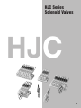
HEA/HEB and HJC/HJE Series
Responds to
various needs for
control!
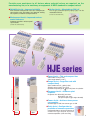
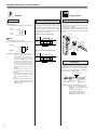
HEA/HEB Series
Compact with large flow rate!
HJC/HJE Series
A small, easy-to-use, simple configuration!
Responsive to varied needs and professional control,
while achieving still lower power consumption levels and
quick response!
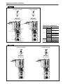
HEA/HEB Series Solenoid Valves
HEA series
(2, 3, 5-port pilot type solenoid valves)
Provides sure assistance to all factors
where solenoid valves are required, on
the manufacturing line, or in machinery
or equipment.
A NEW standard in compact valves!
● Space Assist —Thin and compact size
Valve width: 10mm [0.39in.]
Valve length: 56.7mm [2.23in.] (HEA series)
53mm [2.09in.] (HEB series)
(for standard type)
● Range Assist —Efficient flow rate
56.7mm [2.23in.]
Sonic conductance C: 0.26dm3/(s-bar)
(Effective area: 1.3mm2 [Cv: 0.07])
Optimum for pilot-operated valves, and for operating
up to 25 [0.98in.] bore size cylinders.
● Response Assist —Achieves quick
response
Response time: When ON, max. 6ms
When OFF, max. 7ms
(for quick response type single
solenoid)
● Power Assist —Achieves lower power
consumption
10mm
[0.39in.]
Standard type: 0.55W, Low current type: 0.15W
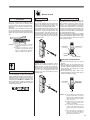
● Reliability Assist —Improved reliability
HEB series
(2, 3-port pilot type solenoid valves)
New solenoid configuration and stem configuration
congregating valve technology have boosted working
life, response, and other basic performance.
● Environment Assist —Improved
environmental tolerance
Grommet type offers moisture-proof
specifications.
53mm [2.09in.]
INDEX
Characteristics and Product Range --------------------------------------------------------------------------------------------------- 1
Safety Precautions ---------------------------------------------------------------------------------------------------------------------------------------------------------- 6
General Precautions ---------------------------------------------------------------------------------------------------------------------------------------------------- 8
Handling Instructions and Precautions ----------------------------------------------------------------------------------------- 9
HEA Series Specifications ------ 13 HJC Series Specifications ------- 37
Order Code --------------- 41
Order Code -------------- 17
Dimensions --------------- 44
Dimensions -------------- 20
HEB Series Specifications ------ 25 HJE Series Specifications ------- 51
Order Code --------------- 55
Order Code -------------- 29
Dimensions --------------- 58
Dimensions -------------- 32
10mm
[0.39in.]
1
Caution
Always read the “Safety Precautions” on page 6 before use.
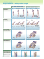
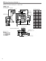
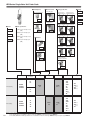
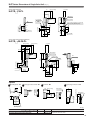
—Variation Assist—
Responds with a wide product range
HEA Series Solenoid Valves
Single unit
(direct piping)
Single
solenoid
HEA10
Double
solenoid
F5
HEA10
(for 2, 3-port
valves)
HEB Series Solenoid Valves
Normally closed (NC)
HEB10
HEB10
F6
F1
F3
Normally open (NO)
HEB10
HEB10
F2
F4
p.20
Single unit
(base piping)
HEA10
F type manifold
(direct piping type)
HEA10
A6-25
p.20
A1-25
A3-25
HEB10
HEB10
F
A
HEBM
p.22
Standard type: Blue
HEAM
AJ
p.22
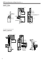
Normally open (NO)
HEB10
HEB10
A2-25
A4-25
p.32
Manifold for 2, 3-port valves
Manifold with combined mounting of 2, 3, 5-port valves
HEAM
Function-specific
solenoids (for both
HEA and HEB series)
A5-25
Normally closed (NC)
Manifold with combined mounting of 2, 3, 5-port valves
HEAM
A, AJ type manifold
(base piping type)
Double
solenoid
Single
solenoid
p.32
F
p.33
Manifold for 2, 3-port valves
HEBM
Low current type: Light blue
A
HEBM
AJ
p.33
Quick response type: White
● Standard type, low current
type and quick response
type can be identified by
the color of the housing.
2
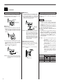
Easy-to-use, simple configuration!
Responsive to varied needs and professional control, while
achieving still lower power consumption levels, quick response
and large flow rate!
HJC/HJE Series Solenoid Valves
(2, 3, 5-port pilot type solenoid valves)
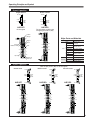
HJC series
● Space Assist —Thin and compact size
Valve width: 10mm [0.39in.]
Valve length: 65.4mm [2.58in.]
● Range Assist— Large flow rate with
compact body
65.4mm [2.58in.]
Sonic conductance C: 0.6dm3/(s-bar)
(Effective area S: 3.0mm2 [Cv: 0.17])
Optimum for operating up to 40 [1.58in.] bore size
cylinders.
● Response Assist —Achieves quick
response
Response time: When ON, max. 6ms
When OFF, max. 7ms
(for quick response type single solenoid)
10mm
14mm
[0.39in.]
[0.55in.]
● Power Assist —Achieves lower power
consumption
Standard type: 0.55W, Low current type: 0.15W
Caution
3
Always read the “Safety Precautions” on page 6 before use.
Provides sure assistance to all factors where solenoid valves are required, on the
manufacturing line, or in machinery or equipment. A NEW standard in compact valves!
● Reliability Assist—Improved reliability
New solenoid configuration and stem configuration
congregating valve technology have boosted working
life, response, and other basic performance.
● Option Assist —Mountable on DIN rail
The A type manifold (base piping type) can be
mounted on DIN rail.
(for both HJC and HJE series)
● Environment Assist —Improved environmental tolerance
Grommet type offers moisture-proof
specifications.
(for both HJC and HJE series)
HJE series
● Space Assist —Thin and compact size
Valve width: 12mm [0.47in.]
Valve length: 80mm [3.15in.]
● Range Assist— Large flow rate with
compact body
Sonic conductance C: 1.9dm3/(s-bar)
(Effective area: 9.5mm2 [Cv: 0.53])
Optimum for operating up to 80 [3.15in.] bore size cylinders.
80mm [3.15in.]
● Response Assist —Achieves quick
response
Response time: When ON, max. 6ms
When OFF, max. 10ms
(for quick response type single solenoid)
● Power Assist —Achieves lower power
consumption
Standard type: 0.55W, Low current type: 0.15W
● Safety Assist—Configuration for
prevention of erroneous operations
12mm
18mm
[0.47in.]
[0.71in.]
Configuration boosts safety with inclusion of
manual lever-type override to prevent
erroneous operations. (HJE series only)
4
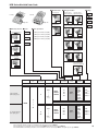
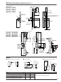
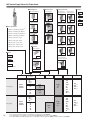
—Variation Assist—
Responds with a wide product range
Single unit
(direct piping)
HJC Series Solenoid Valves
HJE Series Solenoid Valves
Single
solenoid
Single
solenoid
HJC10
Double solenoid
F5
HJC10
3-position
HJC10
HJC10
HJC10
F6
F7
F8
F9
HJE12
Double
solenoid
F5
HJE12
3-position
HJE12
HJE12
HJE12
F6
F7
F8
F9
p.44
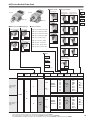
Single unit
(base piping)
Single solenoid
HJC10
A5-25
Double solenoid
HJC10
A6-25
3-position
HJC10
HJC10
HJC10
p.58
Single
solenoid
A7-25
A8-25
A9-25
HJE12
Double
solenoid
A5-25
p.44
F type manifold
(direct piping type)
Manifold with combined mounting of 2, 3, 5-port valves
HJCM
A type manifold
(base piping type)
● Standard type, low current
type and quick response
type can be identified by
the color of the housing.
5
p.47
Manifold with combined mounting of 2, 3, 5-port valves
HJCM
Function-specific
solenoids (for both
HJC and HJE series)
F
A
Standard type: Blue
p.48
HJE12
A6-25
3-position
HJE12
HJE12
HJE12
A7-25
A8-25
A9-25
p.58
Manifold with combined mounting of 2, 3, 5-port valves
HJEM
F
p.61
Manifold with combined mounting of 2, 3, 5-port valves
HJEM
A
Low current type: Light blue
p.62
Quick response type: White
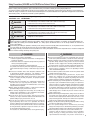
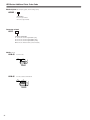
Safety Precautions (HEA/HEB and HJC/HJE Series Solenoid Valves)
Always read these precautions carefully before use.
Before selecting and using products, please read all the Safety Precautions carefully to ensure proper product use.
The Safety Precautions shown below are to help you use the product safely and correctly, and to prevent injury or damage to assets beforehand.
Follow the Safety Precautions for: ISO4414 (Pneumatic fluid power—Recommendations for the application of equipment to transmission
and control systems), JIS B 8370 (Pneumatic system regulations)
The directions are ranked according to degree of potential danger or damage:
CAUTION! and ATTENTION!
DANGER!
WARNING!
DANGER
Expresses situations that can be clearly predicted as dangerous.
If the noted danger is not avoided, it could result in death or serious injury.
It could also result in damage or destruction of assets.
WARNING
Expresses situations that, while not immediately dangerous, could become dangerous.
If the noted danger is not avoided, it could result in death or serious injury.
It could also result in damage or destruction of assets.
CAUTION
Expresses situations that, while not immediately dangerous, could become dangerous.
If the noted danger is not avoided, it could result in light or semi-serious injury.
It could also result in damage or destruction of assets.
ATTENTION
While there is little chance of injury, this content refers to points that should be observed for
appropriate use of the product.
This product was designed and manufactured as parts for use in General Industrial Machinery.
Before selecting the equipment and using any product, always read the Safety Precautions, the Catalog, the Instruction Manual, etc.
After reading the Catalog and Instruction Manual, etc., always place the Manual where it can be easily available for reference to
users of this product.
If transferring or lending the product to another person, always attach the Catalog and Instruction Manual, etc., to the product where
it is easily visible, to ensure that the new user can use the product safely and properly.
The danger, warning, and caution items listed under these “Safety Precautions” do not cover all possible cases. Read the catalog and
user’s manual carefully, and always keep safety first.
DANGER
● Do not use for the purposes listed below:
1. Medical equipment related to maintenance or management of
human lives or bodies.
2. Mechanical devices or equipment designed for the purpose of
moving or transporting people.
3. Critical safety components in mechanical devices.
This product has not been planned or designed for purposes that
require advanced stages of safety. It could cause injury to human
life.
● Do not use in locations with or near dangerous substances such
as flammable or ignitable substances. This product is not an
explosion prevention type. It could ignite or burst into flames.
● When attaching the product, always ensure that it is securely fixed
in place. Dropping or falling the product, or improper operation
could result in injury.
● Persons who use a pacemaker, etc., should keep a distance of at
least one meter (3.3 feet) away from the product. There is the
possibility that the pacemaker will malfunction due to the strong
magnet built into the product.
● Never attempt to rebuild the product. It could result in abnormal
operation leading to injury, electric shock, fire, etc.
● Never attempt inappropriate disassembly or assembly of the
product’s basic configurations, or of its performance or functions.
It could result in injury, electric shock, fire, etc.
● Do not splash water on the product. Spraying it with water,
washing it, or using it underwater could result in malfunction of the
product leading to injury, electric shock, fire, etc.
● Do not touch the product or otherwise bring your body into
physical proximity with it while it is in operation. Also do not
engage in adjustment of the product interior while it is in progress,
or of any accessory items (manual override, release or connection
of wiring connectors, adjustment of pressure switches, or release
or connection of piping tubes or plugs).
The actuator, etc., could suddenly move, causing personal injury.
WARNING
● Do not use this product in excess of its specification range. Such use
could result in product breakdowns, cessation of function, or damage.
● Before supplying air or electricity to the device and before starting
operation, always conduct a safety check of the area of machine
operation. Careless supply of air or electricity could possibly result
in electric shocks, or in injury caused by contact with moving parts.
● Do not touch the terminal and the miscellaneous switches, etc.,
while the device is plugged in. There is the possibility of electric
shock and abnormal operation.
● Do not allow the product to be thrown into fire. The product could
explode and release toxic gases.
● Do not sit on the product, place your foot on it, or place other
objects on it. Accidents such as falling and tripping over could
result in injury. Dropping the product may damage or break the
product resulting in abnormal, improper or erratic operation.
● When conducting any kind of operation for the product, such as
inspection, repair, installation/removal of piping, or replacement,
always shut off the air supply completely and confirm that residual
pressure inside the product or in piping connected to the product
is zero before proceeding. In particular, be aware that residual air
will still be in the air compressor or air storage tank. The actuator
could abruptly move if residual air pressure remains inside the
piping, causing injury.
● Before commencing normal operation, always release the lock on
the locking type manual override, and confirm that the manual
override is in the original position and that the main valve is in the
proper switching position, and only then commence the operation.
Failure to do so could lead to erroneous operation.
● Always shut off power when performing wiring operations. Leaving
the power on could result in electric shocks.
● Use the specified voltage for the solenoid. Using the wrong
voltage level will prevent the solenoid from performing its function,
and could lead to breakage or burn damage of the product itself.
● Avoid scratching the cords for the sensor switch lead wires, etc.
Letting the cords be subject to scratching, excessive bending,
pulling, rolling up, or being placed under heavy objects or
squeezed between two objects, may result in current leaks or
6
●
●
●
●
●
●
●
●
●
●
defective transmission that lead to fires, electric shocks, or
abnormal operation.
Do not pull out the connectors while the power is ON. Also, do not
put unnecessary stress on the connector. It could result in
erroneous equipment operation that could lead to personal injury,
equipment breakdown, or electrical shocks, etc.
Always check the Catalog to ensure that the product wiring and
piping is done correctly. Errors in wiring and piping could lead to
abnormal operation of the actuators, etc.
In initial operations after the equipment has been idle for 48 hours or
more, or has been in storage, there is a possibility that contact parts
will stick, resulting in equipment operation delays or sudden
movements. For these initial operations, always run a test operation
before use to check that operating performance is normal.
In low frequency use (more than 30 days between uses), there is a
possibility that contact parts will stick, resulting in equipment
operation delays or sudden movements that could lead to personal
injury. Run a test operation at a minimum operations frequency of
30 days between tests to confirm that movement is normal.
In double solenoid configurations, do not apply current through both
solenoids simultaneously. It is impossible in such a situation to
maintain the correct valve position, and the equipment may operate
in an unintended direction, leading to the possibility of equipment
breakdown or personal injury.
Do not use the solenoid valves or the wiring that controls them,
near wires where large electrical currents are flowing, or in
locations subject to powerful magnetic fields or power surges.
Such application could lead to unintended operation.
Do not use where ozone may be generated, such as near ocean
beaches or other places subject to direct sunlight or mercury lamps.
Ozone can cause rubber parts to deteriorate, which can lead to
degraded performance and functions, or to equipment stoppages.
(Excludes items where measures against ozone have been taken.)
Do not use any media other than shown on the specifications. Use
of non-specified media could lead to functional shutdown after a short
period, to sudden performance drops, or to shorter operating life.
If mounting the solenoid valve inside a control panel, or if
energizing it for long periods, provide heat radiation measures to
ensure that temperatures surrounding the solenoid valve always
remain within the specified temperature range. If energizing the
unit for long periods, consult with Humphrey Products.
After wiring operations, always check to ensure that no wiring
connection errors exist before turning on the power.
CAUTION
● When mounting the product, leave room for adequate working space
around it. Failure to assure adequate working space will make it more
difficult to conduct daily inspections or maintenance, which could
eventually lead to system shutdown or damage to the product.
● When transporting or installing heavy products, use a lift or
support to firmly hold it up, or use a large number of people, and
take full precautions to ensure personal safety.
● Do not bring floppy disks or other magnetic media within one
meter (3.3 feet) of a solenoid valve when current is passing
through it. The magnetic force could damage the data on the
floppy disk, etc.
● If leakage current is occurring in the control circuit, there is a
possibility of the product performing an unintended operation.
Take measures against current leaking in the control circuit, to
ensure that the leakage current value does not exceed the
allowed range in the product specifications.
● Do not block the product's breathing holes. This will result in
pressure changes due to changes in volume during operation.
Blocking the breathing holes destroys the pressure balance, and
could cause failure of the intentioned operation, equipment
damage, or personal injury.
7
● Do not use the solenoid valve in locations subject to large
electrical currents or magnetic fields. It could result in erroneous
operation.
● Oily materials from the compressor (excluding the oil-free
compressor) can cause drastic deterioration in product
performance, and even a functional shutdown. Always install a
mist filter before pneumatic equipment to remove the oily
component.
● The properties of the lubrication oil can change if using in dry air
where dew point temperatures is lower than -20˚C (-4˚F). It
could result in degraded performance or in functional shutdown.
● Do not use in locations under direct sunlight (ultraviolet), in
locations with high temperature and humidity, in locations
subject to dust, salt, or iron powder, or in the media and/or the
ambient atmospheres that include organic solvents, phosphoric
acid ester-based hydraulic oil, sulfur dioxide gas, chlorine gas
and acids. These conditions could lead to functional shutdowns,
sudden degraded performance, or shortened operating life in
a brief period of time. For the materials used, see Major Parts
and Materials.
ATTENTION
● When considering the possibility of using this product in situations
or environments not specifically noted in the Catalog or
Instruction Manual, or in applications where safety is an important
requirement, such as in an air plane facility, combustion
equipment, leisure equipment, safety equipment and other places
where human life or assets may be greatly affected, take
adequate safety precautions such as application with enough
margins or fail-safe measures for ratings and performance. Please
consult with Humphrey Products about any questions.
● Always check the Catalog and other reference materials for
product wiring and piping.
● Install a muffler, etc., on the exhaust port. It is effective in
reducing exhaust noise.
● When handling the product, wear protective gloves, safety
glasses, safety boots, etc., to ensure safety.
● When the product can no longer be used, or is no longer
necessary, dispose of it appropriately as industrial waste.
● Pneumatic equipment can deliver degraded performance and
function over its operating life. Always conduct daily inspections of
the pneumatic equipment, and confirm that all required system
functions are satisfied, to prevent accidents from happening.
● Air leaks from the valve are not zero. For application of requiring
holding pressure (including vacuum) inside the pressurized
reservoir, consider adequate margin of capacity and holding time
in design of the system.
● For inquiries about the product, see your nearest Humphrey
Products sales office.
OTHER
● Always observe the following items.
1. When using this product in pneumatic systems, always use genuine
Humphrey Products parts or compatible parts (recommended
parts).
When conducting maintenance and repairs, always use
genuine Humphrey Products par ts or compatible par ts
(recommended parts). Always observe the required methods.
2. Do not attempt inappropriate disassembly or assembly of the
product relating to basic configurations, or its performance or
functions.
Humphrey Products cannot be responsible if these items are not
properly observed.
General precautions
Mounting
1. While any mounting direction can be allowed, avoid directly applying
shocks or vibrations on the valves.
2. Avoid using in the locations and environments listed below because
they could result in valve breakdowns. If you must use in such conditions, always provide a cover and take other adequate protective
measures.
● Locations where the valve is directly subjected to dripping water
or oil, etc.
● Environments where moisture condenses on the valve body.
● Locations where the valve is directly subjected to metal chips or
dust.
3. Always thoroughly blow off (use compressed air) the piping before
connecting it to the valve.
Entering chips, sealing tape, rust, etc., generated during piping
work could result in air leaks or other defective operation.
4. The valve cannot be used with the 4 (A) and 2 (B) ports left open.
5. If mounting the valve inside a control panel, or if energizing it for
long periods of time, provide air ventilation or other methods to
effectively radiate the heat.
Media
1. Use air for the media. For the use of any other media, consult with
Humphrey Products.
2. Use clean air that does not contain deteriorated compressor oil or
other contaminants. Install an air filter (with filtration of 40 m or
less) close to the valve to catch any airline condensate or dust.
Moreover, clean the air filter at regular intervals.
3. When the supplied pressure is low, use piping with a sufficiently
large diameter for the 1 (P) port tube.
Lubrication
While the system can be used without lubrication, if you must use oil
for the actuators, etc., use Turbine Oil Class 1 (ISO VG32) or an
equivalent.
Avoid using spindle oil or machine oil. Also be aware that excessive
amounts of lubricating oil can result in defective operation.
Prevention of erroneous operation in the manifold type
Whenever using the manifold type valve, such as operating air
cylinder or performing air blow work, defective operation due to
errors caused by the exhaust or to inadequate flow rate could
occur. Take the countermeasures listed below before starting
use of the manifold type.
1. Erroneous operation due to large exhaust flow rate
Cause:
When using large bore cylinders or simultaneous
operation of a number of cylinders, the pressure of
the collected exhaust can cause the exhaust to
flow back through the exhaust ports of other
solenoid valves, obstructing the operations of
other cylinders, or could cause the air in singleacting cylinders or air hands, etc., to flow
backward, causing errors in operation. The cause
is insufficient exhaust (large exhaust resistance) in
the manifold.
Countermeasure: To reduce exhaust resistance, open the exhaust
ports on both ends. If there is still an exhaust
interference even exhausting on both ends, split
the manifold.
2. Defective operation due to insufficient pressure or flow rate
Cause:
If using a manifold type for operating a large bore
cylinder or simultaneous operation of multiple
cylinders, or for circuits for blowing air, etc., sudden
large consumption of air could result in insufficient
flow into the neighboring cylinder, causing a drop
in speed or a shortage of cylinder thrust. Moreover,
in the pilot type valve, insufficient pressure for the
pilot signal can lead to erroneous operation of the
stem.
Countermeasure: To prevent air supply shortage to the manifold,
supply air from 1(P) ports on the both ends of the
manifold. For air blowing, either separate the air
lines and use individually, or consider using an
external pilot valve.
Atmosphere
The product cannot be used when the media or the ambient
atmosphere contains any of the substances listed below.
Organic solvents, phosphoric acid ester-based hydraulic oil, sulfur
dioxide gas, chlorine gas, or acids, etc.
Wiring
Upon completion of wiring work, always check to confirm that
no wiring misconnection exists.
8
Handling Instructions and Precautions
Plug connector
Solenoid
Internal circuit
Operating principles of low
current and quick response type
12VDC, 24VDC
(Standard type)
Solenoid with LED indicator and surge suppression
Lead wire
Red (+)
(Red)
Lead wire
Black (−)
The low current and quick response type
use a timer circuit, as shown in the above,
that achieves power savings by switching to
holding operations mode after a certain
period of time to operate at about 1/3 of the
start-up power consumption.
Attaching and removing plug connector
Pick up connector with fingers to insert it into
the pin, push in until the lever claw catches the
convex section on the connector housing, and
complete the connection.
To remove the connector, squeeze the lever
along with the connector, lift the lever claw up
from the convex section on the housing, and
pull out.
● Power cycle for low current type
Convex section
Pin
24VDC
(Low current, quick response types)
Solenoid with LED indicator and surge suppression
Power
consumption
Solenoid
valves
0.55W
OFF
Lever
Reduced power
consumption
0.15W
Lead wire
Red (+)
Connector
assembly
Start-up state time(Max. 200ms)
(Red)
Indication of
polarity (DC)
Connector
Timer
circuit
Cautions: 1. Do not apply megger between the pins.
2. Leakage current inside the circuit could
result in failure of the solenoid valve to
return to the rest position or in other
erratic operation. Always use at less than
the allowable leakage current shown in
the solenoid specifications on p.13, 25,
37 and 51. If circuit conditions, etc.,
cause the leakage current to exceed the
maximum allowable leakage current,
consult us.
3. For the double solenoid specification,
avoid energizing both solenoids simultaneously.
4. The standard housing type is colored
blue, while the low current type is light
blue, and the quick response type is
white.
5. The low current type and quick response
type will not activate if the power supply
voltage is raised slowly. Always apply the
appropriate voltage.
● Power cycle for quick response type
Solenoid
valves
Power
consumption
Lead wire
Black (−)
Housing
ON
3W
1.1W
ON
Contact
OFF
Reduced power
consumption
Start-up state time(Max. 30ms)
Crimping of connecting lead wire
and contact
To crimp lead wires into contacts, strip off
4mm [0.16in.] of the insulation from the end of
the lead wire, insert into the contact, and crimp
it. Be sure to avoid catching the insulation on
the expose wire crimping section.
Expose wire 4mm [0.16in.]
Contact
Insulation crimp holder
Hook
Expose wire crimping section
Lead
wire
Applicable wire
AWG#22∼#28
Insulation
(Maximum outer diameter:
φ1.7 [0.07in.])
Cautions: 1. Do not pull the lead wire too hard.
2. Always use the dedicated tool for
crimping of connecting lead wire and
contact.
Contact: Model 702062-2M
Manufactured by Sumiko Tech, Inc.
Crimping tool: Model F1-702062
Manufactured by Sumiko Tech, Inc.
9
Manual override
Attaching and removing connector
and contact
Inser t the contact with a lead wire into a
connector
hole until the contact hook
catches and is secured to the connector.
Confirm that the lead wire cannot be easily
pulled out.
To remove, insert a tool with a fine tip (such as
a small screwdriver) into the rectangular hole
on the side of the connector to push up on the
hook of the contact, and then pull out the lead
wire.
Non-locking type
Lever type (HJE series only)
To operate, press the manual override all
the way down.
In the single solenoid, the valve works the
same as an energized state as long as the
manual override is pushed down, and
returns to the rest position upon release.
In the double solenoid, pressing the manual
override on the 14 (SA) side switches the
state of the 14 (SA) to energized state, and
the unit remains in that state even after the
manual override is released. To return to the
rest position, operate the manual override
on the 12 (SB) side. This is the same for
solenoid 12 (SB).
Cautions: 1. Do not pull the lead wire too hard. It
could result in defective or lost connections.
2. If the pins are bent, use a small
screwdriver to gently bend the pins
back to a straight position, and then
attach the connector to the device.
To lock, push down on the manual lever all the
way down and turn it clockwise 90 degrees.
When locked, turning the manual lever 90
degrees in a counterclockwise direction
returns it to its original position, and releases
the lock. If the manual lever is never turned,
this type acts just like the non-locking type, like
the valve energizing status as long as the
manual lever is pushed down, and returning to
the rest position upon release.
To avoid inadvertently pushing in the manual
lever, a safety plate is provided for prevention
of erroneous operations. Note that the safety
plate cannot be operated when the manual
lever is locked in place.
Manual lever
Safety plate
ON
PUSH
KEEP
PU
SH
LOCK
Locked
position
90°
Push in and turn
Safety plate operating method
Locking type
Precautions for side mounting (HJE series)
If using a unit in the solenoid valve HJE series
in a side mounting, as shown in the diagram
below, mounting base-22 for side mounting is
required because the fitting interferes with the
mounting surface. Note that quick fitting
standard types TS6-M5 and TL6-M5 for the
6mm [0.24in.] tube cannot be mounted. Use
the hexagon socket straight fitting or the quick
fitting mini type instead.
To lock, use a small screwdriver to push
down on the manual override all the way
down and turn it clockwise 45 degrees.
When locked, turning the manual override
45 degrees in a counterclockwise direction
retur ns it to its original position, and
releases the lock. (Excluding the quick
response type)
qCheck that the manual lever is in the off
position.
wSlide the center of the safety plate in the
direction shown by the arrow until it comes
to a stop, a distance of about 3mm [0.12in.].
In this position, the manual lever can no
longer be pushed in.
eTo release the safety plate, slide it in the
direction opposite to that shown by the
arrow, until it comes to a stop.
Manual lever
(Off position)
Safety plate
TURN
KEEP
ON
PUSH
LOCK
Slide
Cautions: 1. The HEA, HEB, HJC, and HJE series are
pilot type solenoid valves. As a result, the
manual override on manual lever cannot
switch the main valve without supplying
air from the 1(P) port.
2. Always release the lock on the manual
override or manual lever before commencing normal operation.
3. Do not attempt to operate the manual
override on the manual lever with a pin
or other object having an extremely fine
tip.
4. For the lever type, do not apply more
force than is necessary when sliding the
safety plate. It could result in an accident. (Recommended force: 3N)
10
Manifold
Mounting on a DIN rail (A type manifold)
A mounting bracket and fixing screw are
provided for mounting on the DIN rail. First of
all, use the fixing screw to temporarily hold the
mounting bracket on the manifold.
Mounting a valve on the manifold
● Removing
qLoosen the fixing screw and lift off the
manifold away from the mounting bracket.
wInsert a flat screwdriver, etc., underneath
the mounting bracket’s release lever, and
gently lift up on the release lever to
remove the mounting bracket.
Fixing screw
If mounting a valve on the manifold, the
recommended tightening torque for the valve
mounting screw is 14.7N・cm {1.5kgf・cm}
[1.30lbf・in.].
Tube
1. Attaching and removing tubes
1
(P)
Mounting bracket
3
(R)
1
(P)
3
(R)
● Mounting
Release lever
qApproaching from the direction shown in the
diagram, let the mounting bracket hook
catch on the DIN rail claw, then press down
on the manifold to insert the tool into the
DIN rail.
(P)
1
(R)
3
wTo ensure that the mounting bracket is firmly
set against the bottom of the manifold,
tighten the fixing screw to fix the DIN rail in
place.
Recommended tightening torque:
98N・cm {10kgf・cm} [8.66lbf・in.]
Cautions: A pent-up reaction force from the mounting bracket’s plate spring could cause
the tool to fly off during the removal operation. To ensure safety, proceed with
caution during the operation. In addition,
always use a flat screwdriver when
removing the mounting bracket from the
DIN rail. Never perform the operation
using your fingers because of the danger
of serious injury due to the strong forces
that may be applied.
● Perpendicular mounting
When mounting the manifold in a perpendicular position, mount it so that the
release lever is pointing downward.
Caution: Be careful to avoid dropping the
manifold.
1
(P)
Tightening
mm [in.]
1
(P)
Caution: Since the mounting bracket cannot slide along
the DIN rail once it is set into the rail, be sure
to set the manifold in the desired position
beforehand.
11
Cautions: 1. Do not use extra-soft tubes since
their pull-out strength reduces
significantly.
2. Only use tubes without scratch on
the outer surface. If scratch is made
during repeated use, cut off the
scratched section.
3. Do not bend the tube excessively
near the fittings.The minimum
bending radius is as shown in the
table below.
4. When attaching or removing tubes,
always stop air supply. In addition,
always confirm that air has been
completely exhausted from the
manifold.
3
(R)
3
(R)
For tube connection, insert an appropriate
size tube as far as contacting with the tube
stopper, and lightly pull it to check the
connection.
For tube removal, push the tube against the
tube stopper, then push the release ring and
at the same time pull the tube out.
2. Either a nylon tube or urethane tube can
be used.
Use tubes with an outer diameter tolerance
within ±0.1mm [0.004in.] of the nominal
diameter, and allowance of out-of-ellipticity
(difference between large diameter and
small diameter) is 0.2mm [0.008in.] or less.
(Using Humphrey Products tubes is
recommended.)
Release lever
Tube size
Minimum bending radius
Nylon tube
Urethane tube
φ4 [0.157]
20 [0.8]
10 [0.4]
φ6 [0.236]
30 [1.2]
15 [0.6]
φ8 [0.315]
50 [2.0]
20 [0.8]
φ3 [0.118]
7 [0.3]
HEA Series
Solenoid Valves
HEA
12
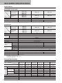
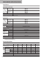
HEA SERIES SPECIFICATIONS
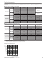
Specifications
Basic Models and Functions
HEA10□F1Note
HEA10□F2Note
HEA10□F3Note
HEA10□F4Note
HEA10□A1Note
HEA10□A2Note
HEA10□A3Note
HEA10□A4Note
Basic model For direct piping and
F type manifold
For base piping
and A, AJ type
manifold
Item
HEA10□F5
HEA10□F6
HEA10□A5
HEA10□A6
2 positions
Number of positions
2, 3 ports
Number of ports
5 ports
Single solenoid NC, NO
Valve function
Single solenoid
Double solenoid
Remark: For the optional specifications and order code, see p.17.
Note: Valves with valve specifications F1, F2, F3, F4, A1, A2, A3, and A4 are for mounting on manifolds only, and cannot be used as a single valve unit.
Specifications
HEA10□F1
HEA10□F2
HEA10□F3
HEA10□F4
HEA10□A1
HEA10□A2
HEA10□A3
HEA10□A4
Basic model For direct piping and
F type manifold
For base piping
and A, AJ type
manifold
Item
HEA10□F5
HEA10□F6
HEA10□A5
HEA10□A6
Air
Media
Internal pilot type
Operation method
Base piping (A, AJ type): 0.26
Flow rate charac- Sonic conductance C dm 3/(s・bar)
teristicsNote 1
Effective area S mm2 [Cv]
Direct piping (F type): 1.3 [0.07]
Port sizeNote 2
M3×0.5
Not required
Lubrication
0.2∼0.7 {2∼7.1} [29∼102psi.]
Operating pressure range MPa {kgf/cm2 }
Proof pressure
1.05 {10.7} [152psi.]
MPa {kgf/cm2 }
Standard type
Response timeNote 3
ms Low current type (L)
ON/OFF
Quick response type (S)
Max. 10/20
Max. 12
Max. 10/50
Max. 12
Max. 6
Max. 6/7
5
Standard type
Maximum operating
Low current type (L)
frequency
Hz
Quick response type (S)
Minimum time to energize for self holdingNote 4
2
10
Shock resistance
50
―
ms
5∼50 [41∼122]
Operating temperature range (atmosphere and media) °C [°F]
1373.0 {140} (Axial direction 147.1 {15})
1373.0 {140} (Axial direction 294.2 {30})
m/s2 {G}
Any
Mounting direction
Notes: 1. For details, see the flow rate characteristics on p.14.
2. For details, see the port size on p.14.
3. Values when air pressure is 0.5MPa [73psi.].
4. For double solenoid valve.
Solenoid Specifications
Rated voltage
Item
Operating voltage range
V
Low current type
Quick response type
Standard Current (When rated voltage is applied) mA (r.m.s)
type
W
Power consumption
Current (When rated Starting mA
voltage is applied)
Holding mA
Power consumption
6VDC
(Standard type)
12VDC
(Standard type)
24VDC
(Standard type)
24VDC
24VDC
(Low current type) (Quick response type)
4.5∼ 5.5
5.4∼ 6.6
10.8∼ 13.2
21.6∼ 26.4
21.6∼ 26.4
21.6∼ 26.4
(5±10%)
(6±10%)
(12±10%)
(24±10%)
(24±10%)
(24±10%)
110
92
46
23
―
―
0.55
0.55
0.55
0.55
―
―
―
―
―
―
23
125
46
―
―
―
―
6.3
Starting
W
―
―
―
―
0.55
3
Holding
W
―
―
―
―
0.15
1.1
ms
―
―
―
―
Max. 200
Max. 30
Allowable leakage current
mA
4.8
4
2
1
0.5
4
Insulation resistance
MΩ
Start-up time (standard time)
Color of LED indicator
Surge suppression (as standard)
13
5VDC
(Standard type)
Min. 100 (value at 500VDC megger)
Red
Flywheel diode
Port Size
Specifications
Single unit
(
2 B), (
4 A)
(
1 P)
3・5
(R)
Direct piping
M3×0.5
M3×0.5
M3×0.5
Base piping (with sub-base)
10-32UNF
10-32UNF
10-32UNF
F type
M3×0.5
10-32UNF
1/8NPT
A type
10-32UNF
1/8NPT
1/8NPT
AJ type
Quick fitting for 5/32 [0.157in.]
1/8NPT
1/8NPT
Ports
Manifold
PR
10-32UNF
Assemble at 3・5 (R) port
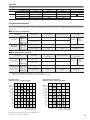
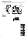
Flow Rate Characteristics
The test method for flow rate characteristics conforms to JIS B 8390:2000 (test method for air pressure — equipment for compressible fluids — flow rate
characteristics).
●When using as a single unit
Flow channel
Sonic conductance C
〔dm3/(s・bar)〕
Critical pressure ratio b
1(P)→ 4(A)
―
―
1(P)→ 2(B)
―
―
4(A)→ 5(R1)
―
―
2(B)→ 3(R2)
―
―
1(P)→ 4(A)
0.26
0.17
1.30 [0.07] Note 3
HEA10□A5
1(P)→ 2(B)
0.22
0.00
1.10 [0.06] Note 3
HEA10□A6
4(A)→ 5(R1)
0.26
0.17
1.30 [0.07] Note 3
2(B)→ 3(R2)
0.26
0.12
1.30 [0.07] Note 3
Sonic conductance C
〔dm3/(s・bar)〕
Critical pressure ratio b
Effective area S
〔mm2〕[Cv]
Basic model
Direct piping
Base piping
(with sub-base)
HEA10□F5
HEA10□F6
Effective area S
〔mm2〕[Cv]
1.30 [0.07]
0.75
[0.04] Note 1
(with fitting)
●When mounted on a manifold
Basic model
Flow channel
―
―
1(P)→4(A)
HEA10□F1
HEA10□F2
―
1
(P)
→2
(B)
HEA10□F3
HEA10□F4
―
4(A)→5(R1)
HEA10□F5
―
2(B)→3(R2)
HEA10□F6
0.26
1(P)→4(A)
HEA10□A1
HEA10□A2
0.26
1(P)→2(B)
A, AJ type manifold
HEA10□A3
(base piping type)
HEA10□A4
0.25
4(A)→5(R1)
HEA10□A5
0.26
2(B)→3(R2)
HEA10□A6
Notes: 1. Quick fitting TS3-M3M has been mounted on connection ports 1(P), 2(B), and 4(A).
2. Quick fitting TS3-M3M has been mounted on connection ports 2(B), and 4(A).
3. Figures in effective area S calculated based on sonic conductance C (S=5.0×C).
―
F type manifold
(direct piping type)
Base piping type
(Effective area S = 1.3mm2 [Cv: 0.07])
0.6
[87]
0.5
[73]
0.4
[58]
0.3
[44]
1.30 [0.07] Note 3
0.18
1.30 [0.07] Note 3
0.26
1.25 [0.07] Note 3
0.20
1.30 [0.07] Note 3
0.6
[87]
0.5
[73]
0.4
[58]
0.3
[44]
0.2
[29]
0.1
[15]
0.1
[15]
0
0
20
40
60
80
100 120 140
[0.71] [1.41] [2.12] [2.82] [3.53] [4.24] [4.94]
Flow rate R/min [ft3/min](ANR)
●
―
0.12
MPa 0.7
[psi.] [102]
0.2
[29]
●
―
0.80
[0.05] Note 2
(with fitting)
Direct piping type with fitting
(Effective area S = 0.75mm2 [Cv: 0.04])
Valve output pressure
Valve output pressure
MPa 0.7
[psi.] [102]
1.30 [0.07]
20
[0.71]
40
[1.41]
60
[2.12]
80
[2.82]
100
[3.53]
Flow rate R/min [ft3/min](ANR)
Graphs use flow rate calculations based on the radiation method.
Treat the flow rate as a general standard.
14
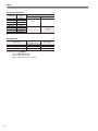
Mass
Single Valve Unit Mass
g [oz]
Additional mass
Basic model
Mass
HEA10□F1
23 [0.81]
HEA10□F2
23 [0.81]
HEA10□F3
23 [0.81]
HEA10□F4
23 [0.81]
HEA10□F5
23 [0.81]
4 [0.14]
HEA10□F6
38 [1.34]
―
HEA10□A1
23 [0.81]
HEA10□A2
23 [0.81]
HEA10□A3
23 [0.81]
HEA10□A4
23 [0.81]
HEA10□A5
23 [0.81]
HEA10□A6
38 [1.34]
-21(with bottom mounting base)
-25 (with sub-base)
―
―
―
―
―
23 [0.81]
Manifold Mass
Basic model
g [oz]
Mass calculation of each unit
(n=number of units)
Block-off plate
HEAM□F
(9 [0.32]×n)+15 [0.53]
3 [0.11]
HEAM□A
(18 [0.63]×n)+38 [1.34]
4 [0.14]
HEAM□AJ
(27.5 [0.97]×n)+50 [1.76]
4 [0.14]
Calculation example: HEAM8AJ
stn.1∼8 HEA10A5-PS-D4
(27.5×8)+50+(23×8) = 454g
[(0.97×8)+1.76+(0.81×8) = 16.00oz]
15
Operating Principle and Symbol
5-port, 2-position
Single solenoid
Double solenoid
14(SA)
4(A)
2(B)
14(SA)
4(A)
2(B)
5(R1)
1(P)
3(R2)
5(R1)
1(P)
3(R2)
12
12(SB)
HEA10F5
HEA10F6
De-energized
De-energized condition after
energizing solenoid 12 (SB)
Column
Plunger
Flapper
Solenoid
Manual override
Piston
Stem
5(R1)
4(A)
5(R1)
4(A)
1(P)
2(B)
1(P)
2(B)
3(R2)
Lip seal
3(R2)
Valve body
End cover
Major Parts and Materials
Parts
Materials
Body
Aluminum alloy
(anodized)
Stem
Lip seal
Flapper
Valve
Synthetic rubber
Mounting base Steel (zinc plated)
Sub-base
Plunger
Column
Aluminum alloy (anodized)
Magnetic stainless
End cover
Plastic
Body
Aluminum alloy (anodized)
Manifold Block-off plate Steel (nickel plated)
Seal
Synthetic rubber
16
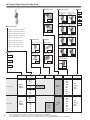
HEA Series Single Valve Unit Order Code
■ Mounting base
Without mounting base
■ Manual override
Non-locking type
■ Voltage
■ Wiring specification
S type plug connector
Lead wire 300mm [12in.]
L type plug connector
Lead wire 300mm [12in.]
-D4
24VDC
-D5
12VDCNote 4
Blank
Blank
With mounting base
Locking type Note 2
-PS
-D6
-PL
6VDCNote 4
S type plug connector
L type plug connector
Lead wire 1000mm [39in.] Lead wire 1000mm [39in.]
-D7
5VDCNote 4
■ Model
■ Valve specification
HEA10
Standard type
HEA10L
Low current type
HEA10S
Quick response type
F1, A1: 2-port normally closed
(NC)Note 1
-81
-21
-PS1
F2, A2: 2-port normally open
(NO)Note 1
F3, A3: 3-port normally closed
(NC)Note 1
F4, A4: 3-port normally open
(NO)Note 1
-PL1
S type plug connector
L type plug connector
Lead wire 3000mm [118in.] Lead wire 3000mm [118in.]
■ Sub-base
Without sub-base
-PS3
F5, A5: 5-port 2-position, single
S type plug connector
Without connector
F6, A6: 5-port 2-position, double
-PL3
L type plug connector
Without connector
Blank
With sub-base
-PSN
-PLN
Grommet typeNote 3
Lead wire 300mm [12in.]
(moisture-proof specification)
-25
-GL
Model
Direct piping
HEA10
HEA10L
HEA10S
Valve
specification
Mounting base
Sub-base
F1Note 1
F2Note 1
F3Note 1
F4Note 1
F5
Manual override
Blank
-81Note 2
Blank
-21
F6
Base piping
HEA10
HEA10L
HEA10S
A1Note 1
A2Note 1
A3Note 1
A4Note 1
A5
A6
17
Blank
-81Note 2
Blank
-25
Wiring specification
Voltage
-PS
-PS1
-PS3
-PSN
-PL
-PL1
-PL3
-PLN
-GLNote 3
-D4
-D5Note 4
-D6Note 4
-D7Note 4
-PS
-PS1
-PS3
-PSN
-PL
-PL1
-PL3
-PLN
-GLNote 3
-D4
-D5Note 4
-D6Note 4
-D7Note 4
Notes: 1. Valves with valve specifications F1, F2, F3, F4, A1, A2, A3, and A4 are for mounting on manifolds only, and cannot be used as a single valve unit.
2. The locking-type manual override is not available for the quick response type HEA10S.
3. The grommet type is not available for the low current type HEA10L and quick response type HEA10S.
4. The 5VDC, 6VDC and 12VDC specifications are not available for the low current type HEA10L and quick response type HEA10S.
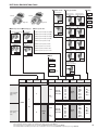
HEA Series Manifold Order Code
■ Manual override
Non-locking type
Left side
Left side
■ Voltage
■ Wiring specification
S type plug connector
Lead wire 300mm [12in.]
L type plug connector
Lead wire 300mm [12in.]
-D4
24VDC
-D5
12VDCNote 4
Right side
Right side
-PS
Locking typeNote 2
■ Manifold specification
F type (direct piping type)
■ Model
F1, A1: 2-port normally closed(NC)
HEA10
S type plug connector
L type plug connector
Lead wire 1000mm [39in.] Lead wire 1000mm [39in.]
6VDCNote 4
-D7
5VDCNote 4
-81
F2, A2: 2-port normally open(NO)
-PS1
F3, A3: 3-port normally closed(NC)
HEA10L
A type (base piping type)
-PL
■ Valve specification
Standard type
F
-D6
Blank
Low current type
-PL1
S type plug connector
L type plug connector
Lead wire 3000mm [118in.] Lead wire 3000mm [118in.]
F4, A4: 3-port normally open(NO)
F5, A5: 5-port 2-position, single
HEA10S
Quick response
type
F6, A6: 5-port 2-position, double
-PS3
S type plug connector
Without connector
-PL3
L type plug connector
Without connector
A
AJ type (with quick fitting)
(base piping type)
-PSN
-PLN
Grommet typeNote 3
Lead wire 300mm [12in.]
(moisture-proof specification)
AJ
-GL
Model
Number of
units
Manifold
Specification
Station
Model
Manifold code
F type manifold
(direct piping type)
stn.1
・
・
・
stn.□
HEA10
HEA10L
HEA10S
Note 1
A , AJ type manifold
(base piping type)
Manual
override
Wiring
specification
Voltage
Mounting valve code
F
HEAM
Valve
specification
2
・
・
・
20
F1
F2
F3
F4
F5
F6
Blank
-81Note 2
-PS
-PS1
-PS3
-PSN
-PL
-PL1
-PL3
-PLN
-GLNote 3
-D4
-D5Note 4
-D6Note 4
-D7Note 4
HEABP-F (for block-off plate)
A
AJ
stn.1
・
・
・
stn.□
Note 1
HEA10
HEA10L
HEA10S
A1
A2
A3
A4
A5
A6
Blank
-81Note 2
-PS
-PS1
-PS3
-PSN
-PL
-PL1
-PL3
-PLN
-GLNote 3
-D4
-D5Note 4
-D6Note 4
-D7Note 4
HEABP-A (for block-off plate)
Notes: 1. Valve mounting location is from the left side of manifold.
2. The locking-type manual override is not available for the quick response type HEA10S.
3. The grommet type is not available for the low current type HEA10L and quick response type HEA10S.
4. The 5VDC, 6VDC and 12VDC specifications are not available for the low current type HEA10L and quick response type HEA10S.
18
HEA Series Additional Parts Order Code
Block-off plate (block-off plate, gasket, and 2 mounting screws)
HEABP Specification
F : For F type manifold
A : For A, AJ type manifold
Connector-related
HEAZ Connector specification
P : Connector, lead wire length 300mm [12in.]
P1 : Connector, lead wire length 1000mm [39in.]
P3 : Connector, lead wire length 3000mm [118in.]
PN : Connector, without lead wire (contacts included)
Muffler mm [in.]
2.5
[0.098]
12
[0.472]
M3×0.5
HKM-05
For valve, sub-base and manifold
3.5
[0.138]
14
[0.551]
10-32UNF
19
φ6[0.236]
For in line valve
φ8[0.315]
HKM-03
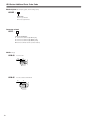
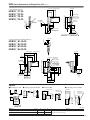
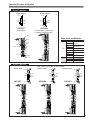
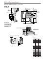
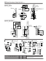
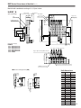
HEA Series Dimensions of Single Valve Unit mm [in.]
5-port single solenoid
30 [1.181]
HEA10□F5-PL
(300) [(11.811)]
10 [0.394]
22 [0.866]
24.8
[0.976]
2.9
[0.114]
6.4
[0.252]
4
(A)
10.9
2
(B)
10.9
[0.429]
3
(R 2)
9.3
[0.366]
φ6 [0.236]
5
(R1)
1
(P)
5-M3×0.5
[0.429]
6.4
[0.252]
12.8 [0.504]
2-φ2.1 [0.083]
(Mounting hole)
For HKM-03
Manual override
9.6
[0.378]
22.5
[0.886]
PR
14.1 [0.555]
56.7 [2.232](SF5:57.4 [2.260])
LED indicator
2
[0.079]
2 [0.079]
7.4 [0.291]
12
14
[0.472] [0.551]
2-φ2.1 [0.083] Counter bore φ3.2 [0.126]
Depth 1 [0.039]
(Mounting hole)
5-port single solenoid (with sub-base)
HEA10□A5-25-PL
(47) [(1.850)]
16
[0.630]
11 [0.433]
5 [0.197]
(300) [(11.811)]
11 [0.433]
10 [0.394]
10 [0.394]
30
[1.181]
22
[0.866]
14
[0.551]
5 [0.197]
LED indicator
(31)
[(1.220)]
9.9
[0.390]
17.5
[0.689]
27.5
[1.083]
PR
1
(P)
3
(R)
29.6
[1.165]
35
[1.378]
φ8 [0.315]
1
[0.039]
2.7
[0.106]
5-10-32UNF
2-φ3.1 [0.122]
(Mounting hole)
For HKM-05
24.8
[0.976]
56.7 [2.232]
(SA5:57.4 [2.260])
3.4
[0.134]
2
(B)
12.3
[0.484]
20 [0.787]
4
(A)
60.1 [2.366] (SA5:60.8 [2.394])
22.5
[0.886]
Manual override
14.3
[0.563]
14
17
[0.669] [0.551]
31
[1.220]
Options
24 [0.945]
27.5 [1.083]
22 [0.866]
28
[1.102]
2-φ3.5 [0.138]
(Mounting hole)
LED indicator
(Total length of valve)
22 [0.866]
B
(300) [(11.811)]
LED indicator
A
(Total length of valve)
C
19.6 (300) [(11.811)]
[0.772]
14
[0.551]
4-
●S type plug connector: -PS
18.5
[0.728]
22.5
[0.886]
2
(B)
●Grommet: -GL
24.8 [0.976]
1.2
[0.047]
●Locking type manual override: -81
3
5 [0.197]
●Mounting base: -21
mm [in.]
Model
HEA10F5, HEA10A1∼H
HEA10A5
HEA10F1∼H
Code
A
B
56.7 [2.232]
61.7 [2.429]
HEA10LF5, HEA10LA1∼H
HEA10LA5
HEA10LF1∼H
−
61.7 [2.429]
HEA10SF5, HEA10SA1∼H
HEA10SA5
HEA10SF1∼H
−
62.4 [2.457]
Remark
Length to the end of the valve
20
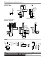
HEA Series Dimensions of Single Valve Unit mm [in.]
5-port double solenoid
HEA10
F6-PL
12 [0.472]
30 [1.181]
10 [0.394]
(300) [(11.811)]
22 [0.866]
LED indicator
14 [0.551]
2-φ2.1 [0.083]
(Mounting hole)
24.8
[0.976]
6.4
[0.252]
5-M3×0.5
4(A)
2
(B)
2 [0.079]
2.9 [0.114]
39.4 [1.551]
(SF6:40.1[1.579])
3
(R2)
39.4 [1.551]
(SF6:40.1 [1.579])
5
(R1)
1
(P)
85.2 [3.354] (SF6:86.6 [3.409])
6.4
[0.252]
For HKM-03
φ6 [0.236]
42.6 [1.677]
(SF6:43.3 [1.705])
12.8 [0.504]
2-PR
9.6 [0.378]
37.8 [1.488]
(SF6:38.5 [1.516])
22.5
[0.886]
Manual override
2-φ2.1 [0.083] Counter bore
φ3.2 [0.126] Depth 1 [0.039]
(Mounting hole)
2 [0.079]
7.4 [0.291]
5-port double solenoid (with sub-base)
A6-25-PL
30
[1.181]
22
[0.866]
14
[0.551]
LED indicator
Manual override
1 [0.039]
11 [0.433]
17
14
[0.669] [0.551]
14.3
[0.563]
10 [0.394]
10 [0.394]
5 [0.197]
PR
9.9
[0.390]
17.5
[0.689]
27.5
[1.083]
1
(P)
3
(R)
35 [1.378]
(SA6:25.8 [1.016])
29.6 [1.165]
2.7 [0.106]
5-10-32UNF
For HKM-05
25.1 [0.988]
85.2 [3.354] (SA6:86.6 [3.409])
2
(B)
12.3
[0.484]
4
(A)
20 [0.787]
31 [1.220]
2-φ3.1 [0.122]
(Mounting hole)
22.5
[0.886]
5 [0.197]
16
[0.630]
11
[0.433]
(300) [(11.811)]
φ8 [0.315]
(47) [(1.850)]
24.8
[0.976]
HEA10
(31)
[(1.220)]
Options
Grommet: -GL
S type plug connector: -PS
24 [0.945]
19.6 (300) [(11.811)]
[0.772]
LED indicator
(Total length of valve)
27.5 [1.083]
A
(Total length of valve)
22 [0.866]
B
(300) [(11.811)]
LED indicator
18.5
[0.728]
22.5
[0.886]
24.8 [0.976]
Locking type manual override: -81
mm [in.]
Model
HEA10F6, HEA10A6
21
Code
A
B
85.2 [3.354]
95.2 [3.748]
HEA10LF6, HEA10LA6
95.2 [3.748]
HEA10SF6, HEA10SA6
96.6 [3.803]
Remark
Length to the end of solenoid on opposite side
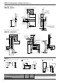
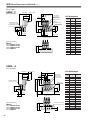
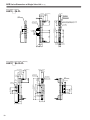
HEA Series Dimensions of Manifold mm [in.]
Manifold with combined mounting of 2, 3, 5-port valves
HEAM
F
(46) [(1.811)]
(300) [(11.811)]
30
[1.181]
22
[0.866]
(Direct piping
type)
L
10.2 [0.402] (Pitch)
13.1 [0.516]
8.1 [0.319]
LED indicator
10 [0.394]
Unit dimensions
Manual override
Number
of units
24.8
[0.976]
2
[0.079]
2
[0.079]
(4)
[(0.157)]
P
Mounting example
(30) [(1.181)]
15
14
[0.591] [0.551]
stn.1 stn.2 stn.3 stn.4 stn.5
HEAM5F
stn.1 HEA10F3-PL-D4
stn.2 HEA10F4-PL-D4
stn.3 HEA10F5-PL-D4
stn.4 HEA10F6-PL-D4
stn.5 HEABP-F
P
2
36.4 [1.433]
28.4 [1.118]
3
46.6 [1.835]
38.6 [1.520]
4
56.8 [2.236]
48.8 [1.921]
5
67.0 [2.638]
59.0 [2.323]
6
77.2 [3.039]
69.2 [2.724]
7
87.4 [3.441]
79.4 [3.126]
8
97.6 [3.843]
89.6 [3.528]
9
107.8 [4.244]
99.8 [3.929]
10
118.0 [4.646] 110.0 [4.331]
11
128.2 [5.047] 120.2 [4.732]
12
138.4 [5.449] 130.4 [5.134]
13
148.6 [5.850] 140.6 [5.535]
14
158.8 [6.252] 150.8 [5.937]
15
169.0 [6.654] 161.0 [6.339]
16
179.2 [7.055] 171.2 [6.740]
17
189.4 [7.457] 181.4 [7.142]
18
199.6 [7.858] 191.6 [7.543]
19
209.8 [8.260] 201.8 [7.945]
20
220.0 [8.661]
212.0[8.346]
A
(52) [(2.047)]
L
15.6 [0.614] 10.2 [0.402] (Pitch)
Unit dimensions
Number
of units
24.8
[0.976]
2-φ3.3 [0.130]
(Mounting hole)
23
[0.906]
38
[1.496]
56.7 [2.232] (SA※:57.4 [2.260])
62.6 [2.465] (SA※:63.3 [2.492]
Manual override
4 [0.157]
(4) [(0.157)]
P
stn.1 stn.2 stn.3 stn.4 stn.5
Plug to 2(B) for mounting HEA10※A1,※A3
2-10-32UNF (For each unit)
P
2
41.4 [1.630]
33.4 [1.315]
3
51.6 [2.031]
43.6 [1.717]
4
61.8 [2.433]
53.8 [2.118]
5
72.0 [2.835]
64.0 [2.520]
6
82.2 [3.236]
74.2 [2.921]
7
92.4 [3.638]
84.4 [3.323]
8
102.6 [4.039]
94.6 [3.724]
9
112.8 [4.441] 104.8 [4.126]
10
123.0 [4.843] 115.0 [4.528]
11
133.2 [5.244] 125.2 [4.929]
12
143.4 [5.646] 135.4 [5.331]
13
153.6 [6.047] 145.6 [5.732]
14
163.8 [6.449] 155.8 [6.134]
15
174.0 [6.850] 166.0 [6.535]
16
184.2 [7.252] 176.2 [6.937]
17
194.4 [7.654] 186.4 [7.339]
18
204.6 [8.055] 196.6 [7.740]
19
214.8 [8.457] 206.8 [8.142]
20
225.0 [8.858] 217.0 [8.543]
9.5
[0.374]
14
[0.551]
2
(B)
6
[0.236]
21
[0.827]
HEAM5A
stn.1 HEA10A3-PL-D4
stn.2 HEA10A4-PL-D4
stn.3 HEA10A5-PL-D4
stn.4 HEA10A6-PL-D4
stn.5 HEABP-A
LED indicator
10 [0.394]
5.9
[0.232]
3.1
[0.122]
1
(P)
Mounting example
(36) [(1.417)]
3
(R)
10
[0.394]
11
[0.433]
10.6
[0.417]
85.2 [3.354] (SA6:86.6 [3.409])
4-1/8NPT (Both sides)
16
[0.630]
(300) [(11.811)]
30
[1.181]
22
[0.866]
22.6 [0.890]
(SA6:23.3 [0.917])
(Base piping
type)
28.9 [1.138]
30
[1.181]
(B) 2
(B)
2
(B) 2
4 [0.157]
HEAM
16
[0.630]
6.4
[0.252]
4
(A) 4
(A)
4
(A)
(SF6:30.2 [1.189])
9.7 [0.382]
2-φ3.3 [0.130]
(Mounting hole)
29.5 [1.161]
2-10-32UNF(Both sides)
8 [0.315]
56.7 [2.232] (SF※:57.4 [2.260])
1
(P)
11 [0.433]
3
(R)
23.5 [0.925]
2-1/8NPT (Both sides)
M3×0.5
10.9
[0.429]
85.2 [3.354] (SF6:86.4 [3.402])
PR
4
(A)
3 [0.118]
3 [0.118]
Plug to 4(A) for mounting HEA10※A2,※A4
22
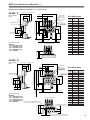
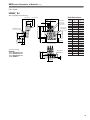
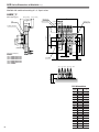
HEA Series Dimensions of Manifold mm [in.]
Manifold with combined mounting of 2, 3, 5-port valves
HEAM
AJ
(Base piping type with quick fitting)
(54) [(2.126)]
(300) [(11.811)]
Unit dimensions
L
30
[1.181]
22
[0.866]
10.6
[0.417]
15.6 10.2 [0.402] (Pitch)
[0.614]
10 [0.394]
LED indicator
Number
of units
11 [0.433]
13 [0.512]
56.7 [2.232]
(SA※:57.4 [2.260])
24.8
[0.976]
24
[0.945]
46
[1.811]
4-φ3.3 [0.130]
(Mounting hole)
7 [0.276]
13.9
[0.547]
14.6 [0.575]
(SA6:15.3 [0.602])
19.5
[0.768]
2.5
[0.098]
1
(P)
38.5
[1.516]
24
[0.945]
3
(R)
70.6 [2.780] (SA※:71.3 [2.807])
4-1/8NPT (Both sides)
85.2 [3.354] (SA6:86.6 [3.409])
Manual override
4 [0.157]
(4) [(0.157)]
P
stn.1 stn.2 stn.3 stn.4 stn.5
23
2
(B)
4
(A)
3 [0.118]
3 [0.118]
6 11
[0.236] [0.433]
Quick fitting for 2-φ4 [0.157]
(For each unit)
14
[0.551]
23
[0.906]
Mounting example
HEAM5AJ
stn.1 HEA10A3-PL-D4
stn.2 HEA10A4-PL-D4
stn.3 HEA10A5-PL-D4
stn.4 HEA10A6-PL-D4
stn.5 HEABP-A
(38) [(1.496)]
Plug to 2(B) for mounting HEA10※A1,※A3
Plug to 4(A) for mounting HEA10※A2,※A4
P
2
41.4 [1.630]
33.4 [1.315]
3
51.6 [2.031]
43.6 [1.717]
4
61.8 [2.433]
53.8 [2.118]
5
72.0 [2.835]
64.0 [2.520]
6
82.2 [3.236]
74.2 [2.921]
7
92.4 [3.638]
84.4 [3.323]
8
102.6 [4.039]
94.6 [3.724]
9
112.8 [4.441] 104.8 [4.126]
10
123.0 [4.843] 115.0 [4.528]
11
133.2 [5.244] 125.2 [4.929]
12
143.4 [5.646] 135.4 [5.331]
13
153.6 [6.047] 145.6 [5.732]
14
163.8 [6.449] 155.8 [6.134]
15
174.0 [6.850] 166.0 [6.535]
16
184.2 [7.252] 176.2 [6.937]
17
194.4 [7.654] 186.4 [7.339]
18
204.6 [8.055] 196.6 [7.740]
19
214.8 [8.457] 206.8 [8.142]
20
225.0 [8.858] 217.0 [8.543]
HEB Series
Solenoid Valves
HEB
24
HEB SERIES SPECIFICATIONS
Specifications
Basic Models and Functions
HEB10□F1
HEB10□F2
HEB10□F3
HEB10□F4
HEB10□A1
HEB10□A2
HEB10□A3
HEB10□A4
2 positions
Basic model For direct piping and
F type manifold
For base piping
and A, AJ type
manifold
Item
Number of positions
2, 3 ports
Number of ports
Single solenoid NC, NO
Valve function
Remark: For the optional specifications and order code, see p.29.
Specifications
HEB10□F1
HEB10□F2
HEB10□F3
HEB10□F4
HEB10□A1
HEB10□A2
HEB10□A3
HEB10□A4
Air
Basic model For direct piping and
F type manifold
For base piping
and A, AJ type
manifold
Item
Media
Operation method
Internal pilot type
Base piping (A, AJ type): 0.26
dm 3/(s・bar)
Flow rate charac- Sonic conductance C
teristicsNote 1
Effective area S mm2 [Cv]
Direct piping (F type): 1.3 [0.07]
Port sizeNote 2
M3×0.5
Lubrication
Not required
Operating pressure range MPa {kgf/cm2 }
Proof pressure
MPa {kgf/cm2 }
Response timeNote 3
ON/OFF
Maximum operating
frequency
Hz
0.2∼0.7 {2∼7.1} [29∼102psi.]
1.05 {10.7} [152psi.]
Standard type
Max. 10/20
Low current type (L)
Max. 10/50
Quick response type (S)
Max. 6/7
5
Standard type
2
Low current type (L)
10
Quick response type (S)
Operating temperature range (atmosphere and media) °C [°F]
Shock resistance
5∼50 [41∼122]
m/s2 {G}
1373.0 {140} (Axial direction 294.2 {30})
Mounting direction
Any
Notes: 1. For details, see the flow rate characteristics on p.26.
2. For details, see the port size on p.26.
3. Values when air pressure is 0.5MPa [73psi.].
Solenoid Specifications
Rated voltage
Item
Operating voltage range
V
Low current type
Quick response type
Standard Current (When rated voltage is applied) mA (r.m.s)
type
W
Power consumption
Current (When rated Starting mA
voltage is applied)
Holding mA
Power consumption
6VDC
(Standard type)
12VDC
(Standard type)
24VDC
(Standard type)
24VDC
24VDC
(Low current type) (Quick response type)
4.5∼ 5.5
5.4∼ 6.6
10.8∼ 13.2
21.6∼ 26.4
21.6∼ 26.4
21.6∼ 26.4
(5±10%)
(6±10%)
(12±10%)
(24±10%)
(24±10%)
(24±10%)
110
92
46
23
―
―
0.55
0.55
0.55
0.55
―
―
―
―
―
―
23
125
46
―
―
―
―
6.3
Starting
W
―
―
―
―
0.55
3
Holding
W
―
―
―
―
0.15
1.1
ms
―
―
―
―
Max. 200
Max. 30
Allowable leakage current
mA
4.8
4
2
1
0.5
4
Insulation resistance
MΩ
Start-up time (standard time)
Color of LED indicator
Surge suppression (as standard)
25
5VDC
(Standard type)
Min. 100 (value at 500VDC megger)
Red
Flywheel diode
Port Size
Specifications
Single unit
(
2 A)
(
1 P)
3(R)
Direct piping
M3×0.5
M3×0.5
M3×0.5
Base piping (with sub-base)
10-32UNF
10-32UNF
10-32UNF
F type
M3×0.5
10-32UNF
1/8NPT
A type
10-32UNF
1/8NPT
1/8NPT
AJ type
Quick fitting for 5/32 [0.157in.]
1/8NPT
1/8NPT
Ports
Manifold
PR
10-32UNF
Assemble at 3(R) port
Flow Rate Characteristics
The test method for flow rate characteristics conforms to JIS B 8390:2000 (test method for air pressure — equipment for compressible fluids — flow rate
characteristics).
●When using as a single unit
Basic model
HEB10□F1
Direct piping
HEB10□F2
HEB10□F3
HEB10□F4
HEB10□A1
Base piping
(with sub-base)
HEB10□A2
HEB10□A3
HEB10□A4
Flow channel
Sonic conductance C
〔dm3/(s・bar)〕
Critical pressure ratio b
1(P)→ 2(A)
―
―
Effective area S
〔mm2〕[Cv]
1.30 [0.07]
0.75
[0.04] Note 1
(with fitting)
2(A)→ 3(R)
―
―
1(P)→ 2(A)
0.23
0.05
1.15 [0.06] Note 3
2(A)→ 3(R)
0.23
0.38
1.15 [0.06] Note 3
Flow channel
Sonic conductance C
〔dm3/(s・bar)〕
Critical pressure ratio b
Effective area S
〔mm2〕[Cv]
1(P)→ 2(A)
―
―
●When mounted on a manifold
Basic model
HEB10□F1
F type manifold
(direct piping type)
HEB10□F2
HEB10□F3
HEB10□F4
HEB10□A1
A, AJ type manifold
(base piping type)
HEB10□A2
HEB10□A3
HEB10□A4
1.30 [0.07]
0.80
[0.05] Note 2
(with fitting)
2(A)→ 3(R)
―
―
1(P)→ 2(A)
0.26
0.21
1.30 [0.07] Note 3
2(A)→ 3(R)
0.24
0.46
1.20 [0.07] Note 3
Notes: 1. Quick fitting TS3-M3M has been mounted on connection ports 1(P), and 2(A).
2. Quick fitting TS3-M3M has been mounted on connection port 2(A).
3. Figures in effective area S calculated based on sonic conductance C (S=5.0×C)
Base piping type
(Effective area S=1.3mm2 [Cv: 0.07])
MPa 0.7
[psi.] [102]
0.6
[87]
Valve output pressure
Valve output pressure
MPa 0.7
[psi.] [102]
0.5
[73]
0.4
[58]
0.3
[44]
0.2
[29]
0.5
[73]
0.4
[58]
0.3
[44]
0.1
[15]
0
0
20
40
60
80
100 120 140
[0.71] [1.41] [2.12] [2.82] [3.53] [4.24] [4.94]
Flow rate R/min [ft3/min](ANR)
●
0.6
[87]
0.2
[29]
0.1
[15]
●
Direct piping type with fitting
(Effective area S=0.75mm2 [Cv: 0.04])
20
[0.71]
40
[1.41]
60
[2.12]
80
[2.82]
100
[3.53]
Flow rate R/min [ft3/min](ANR)
Graphs use flow rate calculations based on the radiation method.
Treat the flow rate as a general standard.
26
Mass
Single Valve Unit Mass
Basic model
Mass
HEB10□F1
22 [0.77]
HEB10□F2
22 [0.77]
HEB10□F3
22 [0.77]
HEB10□F4
22 [0.77]
HEB10□A1
22 [0.77]
HEB10□A2
22 [0.77]
HEB10□A3
22 [0.77]
HEB10□A4
22 [0.77]
g [oz]
Additional mass
-21(with bottom mounting base)
-25 (with sub-base)
4 [0.14]
―
―
17 [0.60]
Manifold Mass
Basic model
g [oz]
Mass calculation of each unit
(n=number of units)
Block-off plate
HEBM□F
(10.5 [0.37]×n)+15 [0.53]
2 [0.07]
HEBM□A
(12.5 [0.44]×n)+19 [0.67]
3 [0.11]
HEBM□AJ
(14 [0.49]×n)+24 [0.84]
3 [0.11]
Calculation example: HEBM8AJ
stn.1∼8 HEB10A3-PS-D4
(14×8)+24+(22×8)=312g
[(0.49×8)+0.84+(0.77×8)=10.92oz]
27
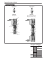
Operating Principle and Symbol
2-port
Normally closed (NC)
Normally open (NO)
12(SA)
2(A)
10(SA)
1(P)
2(A)
10
1(P)
12
HEB10F1
HEB10F2
De-energized
De-energized
Column
Plunger
Major Parts and Materials
Flapper
Manual override
Materials
Body
Aluminum alloy
(anodized)
Stem
Piston
Solenoid
Parts
Lip seal
Synthetic rubber
Flapper
Stem
Valve
Mounting base Steel (zinc plated)
Sub-base
2(A)
2(A)
1(P)
Magnetic stainless
Column
1(P)
Valve body
Lip seal
Aluminum alloy (anodized)
Plunger
End cover
Plastic
Body
Aluminum alloy (anodized)
Manifold Block-off plate Steel (nickel plated)
End cover
Seal
Synthetic rubber
3-port
Normally closed (NC)
12(SA)
2(A)
Normally open (NO)
10(SA)
1(P)
3(R)
2(A)
10
1(P)
3(R)
12
HEB10F3
HEB10F4
De-energized
De-energized
3(R)
2(A)
3(R)
2(A)
1(P)
1(P)
28
HEB Series Single Valve Unit Order Code
■ Mounting base
Without mounting base
■ Manual override
Non-locking type
■ Voltage
■ Wiring specification
S type plug connector
Lead wire 300mm [12in.]
-D4
L type plug connector
Lead wire 300mm [12in.]
24VDC
-D5
12VDCNote 3
Blank
-D6
Blank
-PS
With mounting base
■ Model
HEB10
Standard type
HEB10L
Low current type
HEB10S
Quick response
type
Locking type Note 1
6VDCNote 3
-PL
-D7
S type plug connector
L type plug connector
Lead wire 1000mm [39in.] Lead wire 1000mm [39in.]
5VDCNote 3
■ Valve specification
F1, A1: 2-port normally closed
(NC)
-81
-21
-PS1
F2, A2: 2-port normally open
(NO)
F3, A3: 3-port normally closed
(NC)
F4, A4: 3-port normally open
(NO)
-PL1
S type plug connector
L type plug connector
Lead wire 3000mm [118in.] Lead wire 3000mm [118in.]
■ Sub-base
Without sub-base
-PS3
S type plug connector
Without connector
-PL3
L type plug connector
Without connector
Blank
With sub-base
-PSN
-PLN
Grommet typeNote 2
Lead wire 300mm [12in.]
(moisture-proof specification)
-25
-GL
Model
Valve
specification
Mounting base
Sub-base
Manual override
F1
F2
Direct piping
HEB10
HEB10L
HEB10S
Blank
Blank
-21
-81Note 1
F3
F4
Base piping
29
HEB10
HEB10L
HEB10S
A1
A2
A3
A4
Blank
Blank
-25
-81Note 1
Wiring specification
Voltage
-PS
-PS1
-PS3
-PSN
-PL
-PL1
-PL3
-PLN
-GLNote 2
-D4
-D5Note 3
-D6Note 3
-D7Note 3
-PS
-PS1
-PS3
-PSN
-PL
-PL1
-PL3
-PLN
-GLNote 2
-D4
-D5Note 3
-D6Note 3
-D7Note 3
Notes: 1. The locking-type manual override is not available for the quick response type HEB10S.
2. The grommet type is not available for the low current type HEB10L and quick response type HEB10S.
3. The 5VDC, 6VDC and 12VDC specifications are not available for the low current type HEB10L and quick response type HEB10S.
HEB Series Manifold Order Code
■ Manual Override
Non-locking type
Left side
■ Voltage
■ Wiring specification
S type plug connector
Lead wire 300mm [12in.]
L type plug connector
Lead wire 300mm [12in.]
-D4
24VDC
Left side
-D5
12VDCNote 4
Blank
Right side
Locking typeNote 2
■ Manifold specification
F type (direct piping type)
■ Model
F1, A1: 2-port normally closed(NC)
HEB10
S type plug connector
L type plug connector
Lead wire 1000mm [39in.] Lead wire 1000mm [39in.]
-D6
6VDCNote 4
-D7
5VDCNote 4
-81
F2, A2: 2-port normally open(NO)
-PS1
F3, A3: 3-port normally closed(NC)
HEB10L
A type (base piping type)
-PL
■ Valve specification
Standard type
F
-PS
Right side
Low current type
-PL1
S type plug connector
L type plug connector
Lead wire 3000mm [118in.] Lead wire 3000mm [118in.]
F4, A4: 3-port normally open(NO)
HEB10S
Quick response
type
-PS3
S type plug connector
Without connector
-PL3
L type plug connector
Without connector
A
AJ type (with quick fitting)
(base piping type)
-PSN
-PLN
Grommet typeNote 3
Lead wire 300mm [12in.]
(moisture-proof specification)
AJ
-GL
Model
Number of
units
Manifold
specification
Station
Model
Manifold code
F type manifold
(direct piping type)
Valve
specification
Manual
override
stn.1
・
・
・
stn.□
HEB10
HEB10L
HEB10S
F1
F2
F3
F4
Blank
-81Note 2
Note 1
A , AJ type manifold
(base piping type)
Voltage
Mounting valve code
F
HEBM
Wiring
specification
2
・
・
・
20
-PS
-PS1
-PS3
-PSN
-PL
-PL1
-PL3
-PLN
-GLNote 3
-D4
-D5Note 4
-D6Note 4
-D7Note 4
HEBBP-F (for block-off plate)
A
AJ
stn.1
・
・
・
stn.□
Note 1
HEB10
HEB10L
HEB10S
A1
A2
A3
A4
Blank
-81Note 2
-PS
-PS1
-PS3
-PSN
-PL
-PL1
-PL3
-PLN
-GLNote 3
-D4
-D5Note 4
-D6Note 4
-D7Note 4
HEBBP-A (for block-off plate)
Notes: 1. Valve mounting location is from the left side of manifold.
2. The locking-type manual override is not available for the quick response type HEB10S.
3. The grommet type is not available for the low current type HEB10L and quick response type HEB10S.
4. The 5VDC, 6VDC and 12VDC specifications are not available for the low current type HEB10L and quick response type HEB10S.
30
HEB Series Additional Parts Order Code
Block-off plate (block-off plate, gasket, and 2 mounting screws)
HEBBP Specification
F : For F type manifold
A : For A, AJ type manifold
Connector-related
HEAZ Connector specification
P : Connector, lead wire length 300mm [12in.]
P1 : Connector, lead wire length 1000mm [39in.]
P3 : Connector, lead wire length 3000mm [118in.]
PN : Connector, without lead wire (contacts included)
mm [in.]
For in line valve
2.5
[0.098]
12
[0.472]
M3×0.5
HKM-05
For valve, sub-base and manifold
3.5
[0.138]
14
[0.551]
10-32UNF
31
φ6[0.236]
HKM-03
φ8[0.315]
Muffler
HEB Series Dimensions of Single Valve Unit mm [in.]
30 [1.181]
2, 3-port single solenoid
HEB10□F1-PL
HEB10□F2-PL
HEB10□F3-PL
HEB10□F4-PL
(300) [(11.811)]
10 [0.394]
22
[0.866]
24.8
[0.976]
[0.423]
3-M3×0.5
2
(A)
13.6
2-φ2.1 [0.083]
(Mounting hole)
10.75
Manual override
[0.535]
8.5
[0.335]
9.3
[0.366]
1(P)
8
φ6 [0.236]
10.4
[0.409]
3
(R)
[0.315]
6.4
[0.252]
For HKM-03
Plug
(For F1,F2)
5.9
[0.232]
PR
53 [2.087] (SF※:53.7 [2.114])
22.5
[0.886]
LED indicator
12
14
[0.472] [0.551]
2
[0.079]
7.4 [0.291]
2-φ2.1 [0.083] Counter bore φ3.2 [0.126]
Depth 1 [0.039]
(Mounting hole)
6 [0.236]
5 [0.197]
2, 3-port single solenoid (with sub-base)
(45.5) [(1.791)]
9.5 [0.374]
5 [0.197]
30 [1.181]
22
[0.866]
10 [0.394]
(29.5)
[(1.161)]
17
[0.669]
1
(P)
28 [1.102]
8 [0.315]
1
[0.039]
2.7
[0.106]
(15.5)
14
[(0.610)] [0.551]
3
(R)
2-φ3.1 [0.122]
(Mounting hole)
For HKM-05
φ8
[0.315]
22.6 [0.890]
22.5
[0.886]
42
[1.654]
14
[0.551]
2
(A)
4-10-32UNF
Manual override
53 [2.087] (SA※:53.7 [2.114])
For HKM-05
LED indicator
24.8
[0.976]
14.5
[0.571]
(300) [(11.811)]
0.3
[0.012]
5
[0.197]
PR
HEB10□A1-25-PL
HEB10□A2-25-PL
HEB10□A3-25-PL
HEB10□A4-25-PL
14.3
[0.563]
17
14
[0.669] [0.551]
31
[1.220]
Options
●S type plug connector: -PS
2-φ3.5 [0.138]
(Mounting hole)
HEB10F1∼HEB10F4,HEB10A1∼HEB10A4
LED indicator
(Total length of valve)
18.5
[0.728]
22.5
[0.886]
C
4-
14
[0.551]
22
[0.866]
28
[1.102]
Model
(300) [(11.811)]
24 [0.945]
22 [0.866]
B
LED indicator
27.5 [1.083]
19.6
[0.772]
(300) [(11.811)]
A
(Total length of valve)
2(A)
●Grommet: -GL
24.8
[0.976]
1.2
[0.047]
●Locking type manual override: -81
3
5 [0.197]
●Mounting base: -21
mm [in.]
Code
A
B
53 [2.087]
58 [2.283]
HEB10LF1∼HEB10LF4,HEB10LA1∼HEB10LA4
−
58 [2.283]
HEB10SF1∼HEB10SF4,HEB10SA1∼HEB10SA4
−
58.7 [2.311]
Remark
Length to the end of the valve
32
HEB Series Dimensions of Manifold mm [in.]
For 2, 3-port
(48) [(1.890)]
(300) [(11.811)]
L
30
[1.181]
22
[0.866]
5.5
[0.217]
1
(P)
18
[0.709]
3
(R)
2-10-32UNF (Both sides)
13.6
[0.535]
2-1/8NPT (Both sides)
8.5 [0.335]
LED indicator
Manual override
M3×0.5
24.8
[0.976]
53 [2.087] (SF※:53.7 [2.114])
8
[0.315]
10.2 [0.402] (Pitch)
13
[0.512]
10 [0.394]
2
(A) 2
(A) 2
(A)
36.2 [1.425]
29.2 [1.150]
3
46.4 [1.827]
39.4 [1.551]
4
56.6 [2.228]
49.6 [1.953]
5
66.8 [2.630]
59.8 [2.354]
6
77.0 [3.031]
70.0 [2.756]
7
87.2 [3.433]
80.2 [3.157]
8
97.4 [3.835]
90.4 [3.559]
9
107.6 [4.236]
100.6 [3.961]
10
117.8 [4.638]
110.8 [4.362]
11
128.0 [5.039]
121.0 [4.764]
12
138.2 [5.441]
131.2 [5.165]
13
148.4 [5.843]
141.4 [5.567]
14
158.6 [6.244]
151.6 [5.968]
15
168.8 [6.646]
161.8 [6.370]
14
[0.551]
16
179.0 [7.047]
172.0 [6.772]
17
189.2 [7.449]
182.2 [7.173]
17
[0.669]
(3.5) [(0.138)]
18
199.4 [7.850]
192.4 [7.575]
19
209.6 [8.252]
202.6 [7.976]
20
219.8 [8.654]
212.8 [8.378]
P
Mounting example
HEBM
(32) [(1.260)]
P
2
stn.1 stn.2 stn.3 stn.4
HEBM4F
stn.1 HEB10F1-PL-D4
stn.2 HEB10F3-PL-D4
stn.3 HEB10F4-PL-D4
stn.4 HEBBP-F
Number
of units
2-φ3.3 [0.130]
(Mounting hole)
2 [0.079]
3.5
[0.138]
Unit dimensions
26.5
[1.043]
F
(Direct piping type)
10.5 [0.413]
HEBM
A
(Base piping type)
(300) [(11.811)]
53 [2.087]
(SA※:53.7 [2.114])
24.8
[0.976]
3.6 [0.142]
Number
of units
2
41.4 [1.630]
33.4 [1.315]
3
51.6 [2.031]
43.6 [1.717]
4
61.8 [2.433]
53.8 [2.118]
5
72.0 [2.835]
64.0 [2.520]
6
82.2 [3.236]
74.2 [2.921]
7
92.4 [3.638]
84.4 [3.323]
8
102.6 [4.039]
94.6 [3.724]
9
112.8 [4.441] 104.8 [4.126]
10
123.0 [4.843] 115.0 [4.528]
11
133.2 [5.244] 125.2 [4.929]
12
143.4 [5.646] 135.4 [5.331]
13
153.6 [6.047] 145.6 [5.732]
14
163.8 [6.449] 155.8 [6.134]
15
174.0 [6.850] 166.0 [6.535]
16
184.2 [7.252] 176.2 [6.937]
17
194.4 [7.654] 186.4 [7.339]
18
204.6 [8.055] 196.6 [7.740]
19
214.8 [8.457] 206.8 [8.142]
20
225.0 [8.858] 217.0 [8.543]
17.2
[0.677]
32
[1.260]
2-φ3.3 [0.130]
(Mounting hole)
P
4
[0.157]
(4) [(0.157)]
stn.1 stn.2 stn.3 stn.4
10-32UNF (For each unit)
2
(A)
2 [0.079]
33
LED indicator
Manual override
6
[0.236]
HEBM4A
stn.1 HEB10A1-PL-D4
stn.2 HEB10A3-PL-D4
stn.3 HEB10A4-PL-D4
stn.4 HEBBP-A
10.2 [0.402] (Pitch)
15.6
[0.614] 10 [0.394]
14
[0.551]
Mounting example
(32) [(1.260)]
8.5 [0.335]
10.6
[0.417]
10.6
[0.417]
56.6 [2.228] (SA※:57.3 [2.256])
1
(P)
10 [0.394]
3
(R)
24.5 [0.965]
4-1/8NPT (Both sides)
Unit dimensions
L
30
[1.181]
22
[0.866]
17
[0.669]
(48) [(1.890)]
P
HEB Series Dimensions of Manifold mm [in.]
For 2, 3-port
HEBM
AJ
(Base piping type with quick fitting)
(300) [(11.811)]
30
[1.181]
22
[0.866]
15.6
[0.614]
10 [0.394]
LED indicator
Manual override
53 [2.087]
(SA※:53.7 [2.114])
24.8
[0.976]
56.6 [2.228] (SA※:57.3 [2.256])
10 [0.394]
10.6
[0.417]
3.6 [0.142]
6.7 [0.264]
1
(P)
8.5
[0.335]
3
(R)
24.5 [0.965]
4-1/8NPT (Both sides)
Unit dimensions
L
10.2 [0.402] (Pitch)
10.6
[0.417]
2-φ3.3 [0.130]
(Mounting hole)
17.2
[0.677]
32
[1.260]
(48) [(1.890)]
P
4
[0.157]
(4) [(0.157)]
stn.1 stn.2 stn.3 stn.4
Quick fitting for
φ4 [0.157]
P
2
41.4 [1.630]
33.4 [1.315]
3
51.6 [2.031]
43.6 [1.717]
4
61.8 [2.433]
53.8 [2.118]
5
72.0 [2.835]
64.0 [2.520]
6
82.2 [3.236]
74.2 [2.921]
7
92.4 [3.638]
84.4 [3.323]
8
102.6 [4.039]
94.6 [3.724]
9
112.8 [4.441] 104.8 [4.126]
10
123.0 [4.843] 115.0 [4.528]
11
133.2 [5.244] 125.2 [4.929]
12
143.4 [5.646] 135.4 [5.331]
13
153.6 [6.047] 145.6 [5.732]
14
163.8 [6.449] 155.8 [6.134]
15
174.0 [6.850] 166.0 [6.535]
16
184.2 [7.252] 176.2 [6.937]
17
194.4 [7.654] 186.4 [7.339]
18
204.6 [8.055] 196.6 [7.740]
19
214.8 [8.457] 206.8 [8.142]
20
225.0 [8.858] 217.0 [8.543]
2
(A)
6
[0.236]
17
14
[0.669] [0.551]
HEBM4AJ
stn.1 HEB10A1-PL-D4
stn.2 HEB10A3-PL-D4
stn.3 HEB10A4-PL-D4
stn.4 HEBBP-A
(32) [(1.260)]
Mounting example
Number
of units
1.6 [0.063]
34
35
HJC Series
Solenoid Valves
HJC
36
HJC SERIES SPECIFICATIONS
Specifications
Basic Models and Functions
HJC10□F1Note
HJC10□F2Note
HJC10□F3Note
HJC10□F4Note
HJC10□A1Note
HJC10□A2Note
HJC10□A3Note
HJC10□A4Note
Basic model For direct piping
and F type manifold
For base piping
and A type manifold
Item
Number of positions
HJC10□F5
HJC10□F6
HJC10□F7
HJC10□F8
HJC10□F9
HJC10□A5
HJC10□A6
HJC10□A7
HJC10□A8
HJC10□A9
3 positions
2 positions
Number of ports
5 ports
2, 3 ports
Valve function
Single solenoid
Single solenoid NC, NO
Closed center, exhaust center,
pressure center
Double solenoid
Remark: For the optional specifications and order code, see p.41.
Note: Valves with valve specifications F1, F2, F3, F4, A1, A2, A3, and A4 are for mounting on manifolds only, and cannot be used as a single valve unit.
Specifications
HJC10□F1
HJC10□F2
HJC10□F3
HJC10□F4
HJC10□A1
HJC10□A2
HJC10□A3
HJC10□A4
Basic model For direct piping
and F type manifold
For base piping
and A type manifold
Item
HJC10□F5
HJC10□F6
HJC10□F7
HJC10□F8
HJC10□F9
HJC10□A5
HJC10□A6
HJC10□A7
HJC10□A8
HJC10□A9
Media
Air
Operation method
Internal pilot type
Flow rate characteristicsNote 1
Sonic conductance C dm 3/(s・bar)
0.6
Port sizeNote 2
10-32UNF
Lubrication
Not required
Operating pressure range
MPa {kgf/cm2 }
0.2∼0.7 {2∼7.1} [29∼102psi.]
Proof pressure
MPa {kgf/cm2 }
1.05 {10.7} [152psi.]
Response timeNote 3
ON/OFF
ms
Maximum operating
Hz
frequency
0.25∼0.7 {2.5∼7.1} [36.5∼102psi.]
Standard type
Max. 10/20
Max. 12
Max. 10/30
Low current type (L)
Max. 10/50
Max. 12
Max. 10/60
Quick response type (S)
Max. 6/7
Max. 6
Max. 6/12
50
―
Standard type
5
Low current type (L)
2
Quick response type (S)
ms
Minimum time to energize for self holdingNote 4
10
―
Operating temperature range (atmosphere and media) °C [°F]
5∼50 [41∼122]
m/s2 {G}
Shock resistance
1373.0 {140} (Axial direction 294.2 {30})
1373.0 {140} (Axial direction 147.1 {15}) 1373.0 {140} (Axial direction 195.0 {20})
Mounting direction
Any
Notes: 1. For details, see the flow rate characteristics on p.38.
2. For details, see the port size on p.39.
3. Values when air pressure is 0.5MPa [73psi.]. The values for the 3-position valves are those switching from neutral state.
4. For double solenoid valve.
Solenoid Specifications
Rated voltage
Item
Operating voltage range
V
Low current type
Quick response type
Standard Current (When rated voltage is applied) mA (r.m.s)
type
W
Power consumption
Current (When rated Starting mA
voltage is applied)
Holding mA
Power consumption
6VDC
(Standard type)
12VDC
(Standard type)
24VDC
(Standard type)
24VDC
24VDC
(Low current type) (Quick response type)
4.5∼ 5.5
5.4∼ 6.6
10.8∼ 13.2
21.6∼ 26.4
21.6∼ 26.4
21.6∼ 26.4
(5±10%)
(6±10%)
(12±10%)
(24±10%)
(24±10%)
(24±10%)
110
92
46
23
―
―
0.55
0.55
0.55
0.55
―
―
―
―
―
―
23
125
46
―
―
―
―
6.3
Starting
W
―
―
―
―
0.55
3
Holding
W
―
―
―
―
0.15
1.1
ms
―
―
―
―
Max. 200
Max. 30
Allowable leakage current
mA
4.8
4
2
1
0.5
4
Insulation resistance
MΩ
Start-up time (standard time)
Color of LED indicator
Surge suppression (as standard)
37
5VDC
(Standard type)
Min. 100 (value at 500VDC megger)
Red
Flywheel diode
Flow Rate Characteristics
The test method for flow rate characteristics conforms to JIS B 8390:2000 (test method for air pressure — equipment for compressible fluids — flow rate
characteristics).
●When using as a single unit (with fitting)
Basic model
Flow channel
Sonic conductance C
〔dm3/(s・bar)〕
Critical pressure ratio b
1(P)→ 4(A)
―
―
HJC10□F5
1(P)→ 2(B)
―
―
HJC10□F6
4(A)→ 5(R1)
―
―
Direct piping Note 1
HJC10□F7
HJC10□F8
HJC10□F9
2(B)→ 3(R2)
―
―
1(P)→ 4(A)
―
―
1(P)→ 2(B)
―
―
4(A)→ 5(R1)
―
―
HJC10□A6
Note 1
Base piping
(with sub-base)
HJC10□A7
HJC10□A8
HJC10□A9
2.80 [0.16]
2.50 [0.14]
―
―
1(P)→ 4(A)
0.58
0.40
2.90 [0.16] Note 3
1(P)→ 2(B)
0.57
0.37
2.85 [0.16] Note 3
2(B)→ 3(R2)
HJC10□A5
Effective area S
〔mm2〕[Cv]
4(A)→ 5(R1)
0.51
0.29
2.55 [0.14] Note 3
2(B)→ 3(R2)
0.61
0.26
3.05 [0.17] Note 3
1(P)→ 4(A)
0.52
0.36
2.60 [0.15] Note 3
1(P)→ 2(B)
0.53
0.33
2.65 [0.15] Note 3
4(A)→ 5(R1)
0.49
0.27
2.45 [0.14] Note 3
2(B)→ 3(R2)
0.55
0.27
2.75 [0.15] Note 3
Flow channel
Sonic conductance C
〔dm3/(s・bar)〕
Critical pressure ratio b
Effective area SNote 3
〔mm2〕[Cv]
●When mounted on a manifold (with fitting)
Basic model
F type manifold Note 2
(direct piping type)
HJC10□F1
HJC10□F2
HJC10□F3
HJC10□F4
HJC10□F5
HJC10□F6
HJC10□F7
HJC10□F8
HJC10□F9
A type manifold Note 2
(base piping type)
HJC10□A1
HJC10□A2
HJC10□A3
HJC10□A4
HJC10□A5
HJC10□A6
HJC10□A7
HJC10□A8
HJC10□A9
1(P)→4(A)
0.66
0.54
3.30 [0.19]
1(P)→2(B)
0.62
0.46
3.10 [0.17]
4(A)→5(R1)
0.58
0.33
2.90 [0.16]
2(B)→3(R2)
0.55
0.14
2.75 [0.15]
1(P)→4(A)
0.56
0.41
2.80 [0.16]
1(P)→2(B)
0.56
0.42
2.80 [0.16]
4(A)→5(R1)
0.53
0.32
2.65 [0.15]
2(B)→3(R2)
0.50
0.13
2.50 [0.14]
1(P)→4(A)
0.61
0.33
3.05 [0.17]
1(P)→2(B)
0.60
0.31
3.00 [0.17]
4(A)→5(R1)
0.61
0.08
3.05 [0.17]
2(B)→3(R2)
0.60
0.08
3.00 [0.17]
1(P)→4(A)
0.54
0.29
2.70 [0.15]
1(P)→2(B)
0.54
0.30
2.70 [0.15]
4(A)→5(R1)
0.57
0.08
2.85 [0.16]
2(B)→3(R2)
0.54
0.09
2.70 [0.15]
Notes: 1. Quick fitting TSH6-M5M has been mounted on connection ports 1(P), 2(B), and 4(A).
2. Quick fitting TSH6-M5M has been mounted on connection ports 2(B) and 4(A).
3. Figures in effective area S calculated based on sonic conductance C (S=5.0×C).
(Effective area S=3.0mm2 [Cv: 0.17])
Valve output pressure
MPa 0.7
[psi.] [102]
0.6
[87]
0.5
[73]
0.4
[58]
0.3
[44]
0.2
[29]
0.1
[15]
0
100
[3.53]
200
[7.06]
300
[10.6]
400
[14.1]
Flow rate R/min [ft3/min](ANR)
Graphs use flow rate calculations based on the radiation method.
● Treat the flow rate as a general standard.
●
38
Port Size
Ports
2(B)
, 4(A)
1(P)
3・5(R)
Direct piping
10-32UNF
10-32UNF
M3×0.5
Base piping (with sub-base)
10-32UNF
10-32UNF
10-32UNF
F type
10-32UNF
1/8NPT
1/8NPT
A type
10-32UNF
1/8NPT
1/4NPT
Specifications
Single unit
Manifold
Mass
Single Valve Unit Mass
Mass
Basic model
g [oz]
Additional mass
-21 (with bottom mounting base)
-25 (with sub-base)
HJC10□F1
HJC10□F2
26 [0.92]
―
HJC10□F5
26 [0.92]
4 [0.14]
HJC10□F6
40 [1.41]
HJC10□F3
HJC10□F4
HJC10□F7
HJC10□F8
43 [1.51]
―
―
HJC10□F9
HJC10□A1
HJC10□A2
HJC10□A3
26 [0.92]
―
―
―
27 [0.95]
HJC10□A4
HJC10□A5
26 [0.92]
HJC10□A6
40 [1.41]
HJC10□A7
HJC10□A8
43 [1.51]
HJC10□A9
Manifold Mass
g [oz]
Basic model
Mass calculation of each unit
(n = number of units)
HJCM□F
(12.5 [0.44]×n)+20 [0.70]
HJCM□A
(22.5 [0.79]×n)+42 [1.48]
Block-off plate
With DIN rail mounting
bracket
3 [0.11]
―
15 [0.53]
Calculation example: HJCM8A
stn.1∼8 HJC10A5-PS-D4
(22.5×8)+42+(26×8) = 430g
[(0.79×8)+1.48+(0.92×8) = 15.16oz]
39
Operating Principle and Symbol
5-port, 2-position
Single solenoid
Double solenoid
14(SA)
4(A)
2(B)
14(SA)
4(A)
2(B)
5(R1)
1(P)
3(R2)
12
5(R1)
1(P)
3(R2)
12(SB)
HJC10F5
HJC10F6
De-energized
〔De-energized condition after
energizing solenoid 12 (SB)〕
Column
Major Parts and Materials
Plunger
Flapper
Piston
Solenoid
Materials
Body
Aluminum alloy
(anodized)
Stem
5(R1)
Lip seal
4(A)
Manual override
Parts
Stem
1(P)
5(R1)
Synthetic rubber
Flapper
2(B)
Valve
3(R2)
4(A)
Mounting base Steel (zinc plated)
Sub-base
Aluminum alloy (anodized)
1(P)
Plunger
2(B)
Magnetic stainless
Column
3(R2)
Lip seal
Valve body
End cover
Plastic
End cover
Body
Aluminum alloy (anodized)
Manifold Block-off plate Steel (nickel plated)
Synthetic rubber
Seal
5-port, 3-position
〔Both 14 (SA) and 12 (SB) are de-energized〕
Closed center
4(A)
2(B)
HJC10F7
Exhaust center
14(SA)
12(SB)
5(R1)
1(P)
3(R2)
4(A)
2(B)
HJC10F8
5(R1)
4(A)
12(SB)
1(P)
14(SA)
4(A)
2(B)
HJC10F9
5(R1)
1(P)
3(R2)
12(SB)
5(R1)
4(A)
1(P)
2(B)
3(R2)
5(R1)
1(P)
3(R2)
5(R1)
4(A)
2(B)
Pressure center
14(SA)
1(P)
2(B)
3(R2)
3(R2)
40
HJC Series Single Valve Unit Order Code
■ Manual override
Non-locking type
■ Voltage
■ Wiring specification
S type plug connector
Lead wire 300mm [12in.]
L type plug connector
Lead wire 300mm [12in.]
-D4
24VDC
-D5
12VDCNote 4
Blank
-PS
Locking type Note 2
-D6
-PL
6VDCNote 4
S type plug connector
L type plug connector
Lead wire 1000mm [39in.] Lead wire 1000mm [39in.]
-D7
5VDCNote 4
■ Valve specification
F1, A1: 2-port normally closed (NC)Note 1
-81
F2, A2: 2-port normally open (NO)Note 1
-PS1
F3, A3: 3-port normally closed (NC)Note 1
-PL1
S type plug connector
L type plug connector
Lead wire 3000mm [118in.] Lead wire 3000mm [118in.]
F4, A4: 3-port normally open (NO)Note 1
F5, A5: 5-port 2-position, single
■ Mounting base
■ Sub-base
F6, A6: 5-port 2-position, double
F7, A7: 3-position, closed center
Without mounting base
Without sub-base
F8, A8: 3-position, exhaust center
S type plug connector
Without connector
F9, A9: 3-position, pressure center
Blank
■ Model
-PS3
With mounting base
With sub-base
-PSN
HJC10L
-21
Low current type
-25
HJC10S
-GL
Quick response type
Model
Valve
specification
Mounting base
Sub-base
Manual override
F1Note 1
F2Note 1
F3Note 1
F4Note 1
HJC10
HJC10L
HJC10S
F5
Blank
Blank
-21
-81Note 2
F6
F7
F8
F9
A1Note 1
A2Note 1
A3Note 1
A4Note 1
41
-PLN
Grommet typeNote 3
Lead wire 300mm [12in.]
(moisture-proof specification)
Standard type
Base piping
L type plug connector
Without connector
Blank
HJC10
Direct piping
-PL3
HJC10
HJC10L
HJC10S
A5
A6
A7
A8
A9
Blank
-81Note 2
Blank
-25
Wiring specification
Voltage
-PS
-PS1
-PS3
-PSN
-PL
-PL1
-PL3
-PLN
-GLNote 3
-D4
-D5Note 4
-D6Note 4
-D7Note 4
-PS
-PS1
-PS3
-PSN
-PL
-PL1
-PL3
-PLN
-GLNote 3
-D4
-D5Note 4
-D6Note 4
-D7Note 4
Notes: 1. Valves with valve specifications F1, F2, F3, F4, A1, A2, A3, and A4 are for mounting on manifolds only, and cannot be used as a single valve unit.
2. The locking-type manual override is not available for the quick response type HJC10S.
3. The grommet type is not available for the low current type HJC10L and quick response type HJC10S.
4. The 5VDC, 6VDC and 12VDC specifications are not available for the low current type HJC10L and quick response type HJC10S.
HJC Series Manifold Order Code
■ Manual override
Non-locking type
Left side
Left side
■ Voltage
■ Wiring specification
S type plug connector
Lead wire 300mm [12in.]
L type plug connector
Lead wire 300mm [12in.]
-D4
24VDC
-D5
12VDCNote 4
-PS
Locking typeNote 2
■ Manifold specification ■ Mounting type
F type (direct piping type)
Direct mounting
-D6
Blank
Right side
Right side
S type plug connector
L type plug connector
Lead wire 1000mm [39in.] Lead wire 1000mm [39in.]
F1, A1: 2-port normally closed (NC)
-PS1
-PL1
S type plug connector
L type plug connector
Lead wire 3000mm [118in.] Lead wire 3000mm [118in.]
F4, A4: 3-port normally open (NO)
A type (base piping type)
-D7
5VDCNote 4
-81
F3, A3: 3-port normally closed (NC)
Blank
6VDCNote 4
■ Valve specification
F2, A2: 2-port normally open (NO)
F
-PL
F5, A5: 5-port 2-position, single
With DIN rail mounting
F6, A6: 5-port 2-position, double
bracket
(A type manifold only)
F7, A7: 3-position, closed center
-PS3
F8, A8: 3-position, exhaust center
S type plug connector
Without connector
F9, A9: 3-position, pressure center
-PL3
L type plug connector
Without connector
A
-DN
Mounting bracket is
included.
■ Model
-PSN
HJC10
-PLN
Grommet typeNote 3
Lead wire 300mm [12in.]
(moisture-proof specification)
Standard type
HJC10L
Low current type
HJC10S
Quick response type
Model
Number of
units
Manifold
specification
Mounting type
Station
Model
Manifold model
F type manifold
(direct piping
type)
stn.1
・
・
・
stn.□
HJC10
HJC10L
HJC10S
Note 1
A type manifold
(base piping
type)
Valve
specification
Manual
override
Wiring
specification
Voltage
Mounting valve code
F
HJCM
-GL
2
・
・
・
20
F1
F2
F3
F4
F5
F6
F7
F8
F9
Blank
-81Note 2
-PS
-PS1
-PS3
-PSN
-PL
-PL1
-PL3
-PLN
-GLNote 3
-D4
-D5Note 4
-D6Note 4
-D7Note 4
HJCBP (for block-off plate)
A
Blank
-DN
stn.1
・
・
・
stn.□
Note 1
HJC10
HJC10L
HJC10S
A1
A2
A3
A4
A5
A6
A7
A8
A9
Blank
-81Note 2
-PS
-PS1
-PS3
-PSN
-PL
-PL1
-PL3
-PLN
-GLNote 3
-D4
-D5Note 4
-D6Note 4
-D7Note 4
HJCBP (for block-off plate)
Notes: 1. Valve mounting location is from the left side of manifold.
2. The locking-type manual override is not available for the quick response type HJC10S.
3. The grommet type is not available for the low current type HJC10L and quick response type HJC10S.
4. The 5VDC, 6VDC and 12VDC specifications are not available for the low current type HJC10L and quick response type HJC10S.
42
HJC Series Additional Parts Order Code
Block-off plate (block-off plate and 2 mounting screws)
HJCBP
Connector-related
HEAZ Connector specification
P : Connector, lead wire length 300mm [12in.]
P1 : Connector, lead wire length 1000mm [39in.]
P3 : Connector, lead wire length 3000mm [118in.]
PN : Connector, without lead wire (contacts included)
DIN rail mounting bracket (with screws)
HJCZ -DN
mm [in.]
2.5
[0.098]
For in line valve
12
[0.472]
M3×0.5
HKM-05
3.5
[0.138]
For valve, sub-base and manifold
14
[0.551]
10-32UNF
43
φ6[0.236]
HKM-03
φ8[0.315]
Muffler
HJC Series Dimensions of Single Valve Unit mm [in.]
5-port single solenoid
HJC10
(300) [(11.811)]
30
[1.181]
F5-PL
10 [0.394]
22
[0.866]
2-M3×0.5
24.8
[0.976]
4
(A)
2
(B)
2.8 [0.110]
12.7 9.8
[0.500] [0.386]
3
(R2)
16.6
[0.654]
φ6 [0.236]
1
(P)
2-φ1.7 [0.067] Counter bore φ3.2 [0.126]
Depth 1 [0.039] (Mounting hole)
9.3
[0.366]
5(R1)
Manual override
65.4
[2.575]
2-φ2.1 [0.083]
(Mounting hole)
For HKM-03
13.1 9
[0.516] [0.354]
8.4
8.4
[0.331] [0.331]
17.6 [0.693]
PR
(Built-in muffler)
22.5
[0.886]
LED indicator
3-10-32UNF
7.6 [0.299]
12
14
[0.472] [0.551]
5-port single solenoid (with sub-base)
HJC10
A5-25-PL
(46.7) [(1.839)]
16
[0.630]
11
[0.433]
5 [0.197]
(300) [(11.811)]
10 [0.394]
30
[1.181]
22
[0.866]
14
[0.551]
1
(P)
8.1
[0.319]
3
(R)
33 [1.299]
27 [1.063]
φ8 [0.315]
16.5
[0.650]
24.8
[0.976]
65.4
[2.575]
2
[0.079]
(30.7)
[(1.209)]
PR
(Built-in muffler)
2-φ3.2 [0.126]
(Mounting hole)
For HKM-05
3
[0.118]
4-10-32UNF
Manual override
1.1 [0.043]
2
(B)
12.3 [0.484]
4
(A)
20.7 [0.815]
22.5
[0.886]
LED indicator
5 [0.197]
17
[0.669]
20
14
[0.787] [0.551]
34
[1.339]
11
[0.433]
Options
24
[0.945]
22
[0.866]
27.5
[1.083]
LED indicator
A
(Total length of valve)
C
4-
14
[0.551]
22.5
[0.886]
19.6 (300) [(11.811)]
[0.772]
22
[0.866]
28
[1.102]
2-φ3.5 [0.138]
(Mounting hole)
(300) [(11.811)]
B
(Total length of valve)
S type plug connector: -PS
18.5
[0.728]
2
(B)
Grommet: -GL
24.8
[0.976]
1.2 [0.047]
Locking type manual override: -81
3
5 [0.197]
Mounting base: -21
LED indicator
mm [in.]
Model
HJC10F5, HJC10A5
HJC10LF5, HJC10LA5, HJC10SF5, HJC10SA5
Code
A
B
65.4 [2.575]
70.4 [2.772]
70.4 [2.772]
Remark
Length to the end of the valve
44
HJC Series Dimensions of Single Valve Unit mm [in.]
5-port double solenoid
HJC10
F6-PL
12 [0.472]
30 [1.181]
(300) [(11.811)]
10 [0.394]
22
[0.866]
14
[0.551]
φ6 [0.236]
9
[0.354]
For HKM-03
4
(A)
2
(B)
3-10-32UNF
2-φ2.1 [0.083]
(Mounting hole)
2.8 [0.110]
42.9
[1.689]
2-M3×0.5
43.3
[1.705]
3(R2)
39.5
[1.555]
1(P)
9.8
[0.386]
5(R1)
2-φ1.7 [0.067] Counter bore φ3.2 [0.126]
Depth 1 [0.039] (Mounting hole)
16.6
[0.654]
95.6 [3.764]
8.4 [0.331] 8.4 [0.331]
47.8 [1.882]
2-PR
(Built-in muffler)
Manual override
24.8
[0.976]
22.5
[0.886]
LED indicator
7.6 [0.299]
5-port double solenoid (with sub-base)
A6-25-PL
2-φ3.2 [0.126]
(Mounting hole)
(30.7)
[(1.209)]
45
16.5
[0.650]
1
(P)
8.1
[0.319]
31.3
[1.232]
For HKM-05
2-PR
(Built-in muffler)
3
(R)
95.6
[3.764]
2
(B)
20.7
[0.815]
12.3
[0.484]
4
(A)
4-10-32UNF
LED indicator
Manual override
33 [1.299]
2
[0.079]
22.5
[0.886]
5 [0.197]
30
[1.181]
22
[0.866]
14
[0.551]
27 [1.063]
16
[0.630]
34 [1.339]
20
14
[0.787] [0.551]
17
[0.669]
10 [0.394]
φ8 [0.315]
11 [0.433]
(300) [(11.811)]
3
[0.118]
(46.7) [(1.839)]
24.8
[0.976]
HJC10
5 [0.197]
11
[0.433]
HJC Series Dimensions of Single Valve Unit mm [in.]
5-port, 3-position
30 [1.181]
12
[0.472]
HJC10□F7-PL
HJC10□F8-PL
HJC10□F9-PL
(300) [(11.811)]
10 [0.394]
22
[0.866]
14
[0.551]
2-PR
(Built-in muffler)
Manual override
24.8
[0.976]
22.5
[0.886]
LED indicator
2-φ2.1 [0.083]
(Mounting hole)
3-10-32UNF
2.8 [0.110]
2
[0.079]
1
(P)
2-PR
(Built-in muffler)
8.1
[0.319]
3
(R)
33 [1.299]
φ8 [0.315]
105.6
[4.157]
Manual override
40.3
[1.587]
4-10-32UNF
16.5
[0.650]
24.8
[0.976]
LED indicator
2
(B)
12.3 [0.484]
4
(A)
20.7 [0.815]
20
14
[0.787] [0.551]
17
[0.669]
10 [0.394]
27 [1.063]
5 [0.197]
34 [1.339]
30
[1.181]
22
[0.866]
14
[0.551]
22.5
[0.886]
HJC10□A7-25-PL
HJC10□A8-25-PL
HJC10□A9-25-PL
(300) [(11.811)]
(46.7) [(1.839)]
16
[0.630]
11
[0.433]
7.6 [0.299]
3
[0.118]
5-port, 3-position (with sub-base)
9.8
[0.386]
2
(B)
48.5
[1.909]
2-M3×0.5
52.3
[2.059]
φ6 [0.236]
3(R2)
4
(A)
51.9 [2.043]
For HKM-03
1(P)
16.6
[0.654]
9
[0.354]
5(R1)
105.6 [4.157]
56.8
[2.236] 8.4 [0.331] 8.4 [0.331]
2-φ1.7 [0.067] Counter bore φ3.2 [0.126]
Depth 1 [0.039] (Mounting hole)
5 [0.197]
For HKM-05
11
[0.433]
2-φ3.2 [0.126]
(Mounting hole)
(30.7)
[(1.209)]
Options
●S type plug connector: -PS
19.6 (300) [(11.811)]
[0.772]
Code
24
[0.945]
22
[0.866]
A
B
HJC10F6, HJC10A6
95.6 [3.764]
105.6 [4.157]
HJC10F7∼HJC10F9, HJC10A7∼HJC10A9
105.6 [4.157] 115.6 [4.551]
HJC10LF6, HJC10LA6, HJC10SF6, HJC10SA6
−
105.6 [4.157]
HJC10LF7∼HJC10LF9, HJC10LA7∼HJC10LA9
HJC10SF7∼HJC10SF9, HJC10SA7∼HJC10SA9
−
115.6 [4.551]
27.5
[1.083]
A
(Total length of valve)
22.5
[0.886]
18.5
[0.728]
Model
LED indicator
Remark
(300) [(11.811)]
B
(Total length of valve)
●Grommet: -GL
24.8
[0.976]
●Locking type manual override: -81
LED indicator
mm [in.]
mm
Length to the end of solenoid on opposite side
46
HJC Series Dimensions of Manifold mm [in.]
Manifold with combined mounting of 2, 3, 5-port valves
HJCM□F
(46.7) [(1.839)]
(direct piping type)
(300) [(11.811)]
LED indicator
L
10.5 [0.413] (Pitch)
30
[1.181]
22
[0.866]
9 [0.354]
Manual override
14
[0.551]
10 [0.394]
10-32UNF
2-φ4.5 [0.177]
(Mounting hole)
3(R)
1(P)
1(P)
2(B)
2(B)
2(B)
2(B)
30.3 [1.193]
9
[0.354]
〔Mounting example〕
4
[0.157]
HJCM6F
stn.1 HJC10F3-PL-D4
stn.2 HJC10F4-PL-D4
stn.3 HJC10F5-PL-D4
stn.4 HJC10F6-PL-D4
stn.5 HJC10F7-PL-D4
stn.6 HJCBP
P
38 [1.496]
4(A)
23 [0.906]
4(A)
39.3 [1.547]
4(A)
105.6 [4.157]
3(R)
4(A)
0.1
[0.004]
65.4 [2.575]
95.6 [3.764]
14.5
[0.571]
31 [1.220]
4-1/8NPT (Both sides)
12.6 9.8 [0.386]
[0.496]
24.8
[0.976]
PR
(Built-in muffler)
(4)
[(0.157)]
16
14
[0.630] [0.551]
(30.7) [(1.209)]
stn.1 stn.2 stn.3 stn.4 stn.5 stn.6
Unit dimensions
47
Number
of units
L
2
38.5 [1.516]
30.5 [1.201]
3
49.0 [1.929]
41.0 [1.614]
4
59.5 [2.343]
51.5 [2.028]
5
70.0 [2.756]
62.0 [2.441]
6
80.5 [3.169]
72.5 [2.854]
7
91.0 [3.583]
83.0 [3.268]
8
101.5 [3.996]
93.5 [3.681]
9
112.0 [4.409]
104.0 [4.094]
10
122.5 [4.823]
114.5 [4.508]
11
133.0 [5.236]
125.0 [4.921]
12
143.5 [5.650]
135.5 [5.335]
13
154.0 [6.063]
146.0 [5.748]
14
164.5 [6.476]
156.5 [6.161]
15
175.0 [6.890]
167.0 [6.575]
16
185.5 [7.303]
177.5 [6.988]
17
196.0 [7.717]
188.0 [7.402]
18
206.5 [8.130]
198.5 [7.815]
19
217.0 [8.543]
209.0 [8.228]
20
227.5 [8.957]
219.5 [8.642]
P
HJC Series Dimensions of Manifold mm [in.]
Manifold with combined mounting of 2, 3, 5-port valves
HJCM□A
55.7 [2.193]
(base piping type)
(300) [(11.811)]
L
30
[1.181]
22
[0.866]
10 [0.394]
Manual override
47 [1.850]
39.8 [1.567]
0.6
[0.024]
30.8 [1.213]
11
[0.433]
18
[0.709]
105.6 [4.157]
25 [0.984]
95.6 [3.764]
1(P)
17
[0.669]
3(R)
35 [1.378]
2-1/8NPT(Both sides)
2-φ4.5 [0.177]
(Mounting hole)
65.4 [2.575]
2-1/4NPT(Both sides)
3.1
[0.122]
LED indicator
24.8
[0.976]
PR
(Built-in muffler)
10.5 [0.413] (Pitch)
15
[0.591]
10 [0.394]
〔Mounting example〕
5
[0.197]
HJCM6A
stn.1 HJC10A3-PL-D4
stn.2 HJC10A4-PL-D4
stn.3 HJC10A5-PL-D4
stn.4 HJC10A6-PL-D4
stn.5 HJC10A7-PL-D4
stn.6 HJCBP
(5)
[(0.197)]
P
stn.1 stn.2 stn.3 stn.4 stn.5 stn.6
4(A)
2.5
[0.098]
6.5 11
[0.256] [0.433]
14
[0.551]
2(B)
3.5
[0.138]
●DIN rail mounting bracket (-DN)
(7.3) [(0.287)]
2-10-32UNF (For each unit)
25
[0.984]
(39.7) [(1.563)]
Plug to 2 (B) for mounting HJC10※A1,※A3
Plug to 4 (A) for mounting HJC10※A2,※A4
2 [0.079]
24.5
[0.965]
1(P)
(5.2)
[(0.205)]
3(R)
(48.6) [(1.913)]
Unit dimensions
Number
of units
L
2
40.5 [1.594]
30.5 [1.201]
3
51.0 [2.008]
41.0 [1.614]
4
61.5 [2.421]
51.5 [2.028]
5
72.0 [2.835]
62.0 [2.441]
6
82.5 [3.248]
72.5 [2.854]
7
93.0 [3.661]
83.0 [3.268]
8
103.5 [4.075]
93.5 [3.681]
9
114.0 [4.488]
104.0 [4.094]
10
124.5 [4.902]
114.5 [4.508]
11
135.0 [5.315]
125.0 [4.921]
12
145.5 [5.728]
135.5 [5.335]
13
156.0 [6.142]
146.0 [5.748]
14
166.5 [6.555]
156.5 [6.161]
15
177.0 [6.968]
167.0 [6.575]
16
187.5 [7.382]
177.5 [6.988]
17
198.0 [7.795]
188.0 [7.402]
18
208.5 [8.209]
198.5 [7.815]
19
219.0 [8.622]
209.0 [8.228]
20
229.5 [9.035]
219.5 [8.642]
P
48
49
HJE Series
Solenoid Valves
HJE
50
HJE SERIES SPECIFICATIONS
Specifications
Basic Models and Functions
HJE12□F1Note
HJE12□F2Note
HJE12□F3Note
HJE12□F4Note
HJE12□A1Note
HJE12□A2Note
HJE12□A3Note
HJE12□A4Note
Basic model For direct piping
and F type manifold
For base piping
and A type manifold
Item
Number of positions
HJE12□F5
HJE12□F6
HJE12□F7
HJE12□F8
HJE12□F9
HJE12□A5
HJE12□A6
HJE12□A7
HJE12□A8
HJE12□A9
3 positions
2 positions
Number of ports
5 ports
2, 3 ports
Valve function
Single solenoid NC, NO
Single solenoid
Closed center, exhaust center,
pressure center
Double solenoid
Remark: For the optional specifications and order code, see p.55.
Note: Valves with valve specifications F1, F2, F3, F4, A1, A2, A3, and A4 are for mounting on manifolds only, and cannot be used as a single valve unit.
Specifications
HJE12□F1
HJE12□F2
HJE12□F3
HJE12□F4
HJE12□A1
HJE12□A2
HJE12□A3
HJE12□A4
Basic model For direct piping
and F type manifold
For base piping
and A type manifold
Item
HJE12□F5
HJE12□F6
HJE12□F7
HJE12□F8
HJE12□F9
HJE12□A5
HJE12□A6
HJE12□A7
HJE12□A8
HJE12□A9
Media
Air
Operation method
Internal pilot type
Flow rate characteristicsNote 1
Sonic conductance C dm 3/(s・bar)
Base piping (A type): 1.9
Direct piping (F type): 10-32UNF, base piping (A type): 1/8NPT
Port sizeNote 2
Lubrication
Not required
Operating pressure range
MPa {kgf/cm2 }
Proof pressure
Response timeNote 3
ON/OFF
0.2∼0.7 {2∼7.1} [29∼102psi.]
MPa {kgf/cm2 }
ms
Maximum operating
Hz
frequency
1.05 {10.7} [152psi.]
Standard type
Max. 12/28
Max. 20
Max. 12/30
Low current type (L)
Max. 12/60
Max. 20
Max. 12/60
Quick response type (S)
Max. 6/10
Max. 8
Max. 6/10
50
―
Standard type
5
Low current type (L)
2
Quick response type (S)
ms
Minimum time to energize for self holdingNote 4
10
―
Operating temperature range (atmosphere and media) °C [°F]
5∼50 [41∼122]
m/s2 {G}
Shock resistance
1373.0 {140} (Axial direction 294.2 {30})
1373.0 {140} (Axial direction 245.0 {25})
Mounting direction
Any
Notes: 1. For details, see the flow rate characteristics on p.52.
2. For details, see the port size on p.53.
3. Values when air pressure is 0.5MPa [73psi.]. The values for the 3-position valves are those switching from neutral state.
4. For double solenoid valve.
Solenoid Specifications
Rated voltage
Item
Operating voltage range
V
Low current type
Quick response type
Standard Current (When rated voltage is applied) mA (r.m.s)
type
W
Power consumption
Current (When rated Starting mA
voltage is applied)
Holding mA
Power consumption
6VDC
(Standard type)
12VDC
(Standard type)
24VDC
(Standard type)
24VDC
24VDC
(Low current type) (Quick response type)
4.5∼ 5.5
5.4∼ 6.6
10.8∼ 13.2
21.6∼ 26.4
21.6∼ 26.4
21.6∼ 26.4
(5±10%)
(6±10%)
(12±10%)
(24±10%)
(24±10%)
(24±10%)
110
92
46
23
―
―
0.55
0.55
0.55
0.55
―
―
―
―
―
―
23
125
46
―
―
―
―
6.3
Starting
W
―
―
―
―
0.55
3
Holding
W
―
―
―
―
0.15
1.1
Start-up time (standard time)
Allowable leakage current
ms
―
―
―
―
Max. 200
Max. 30
mA
4.8
4
2
1
0.5
4
Insulation resistance
MΩ
Color of LED indicator
Surge suppression (as standard)
51
5VDC
(Standard type)
Min. 100 (value at 500VDC megger)
Red
Flywheel diode
Flow Rate Characteristics
The test method for flow rate characteristics conforms to JIS B 8390:2000 (test method for air pressure — equipment for compressible fluids — flow rate
characteristics).
●When using as a single unit (with fitting)
Basic model
Direct piping
Flow channel
Sonic conductance C
〔dm3/(s・bar)〕
Critical pressure ratio b
Effective area S Note 5
〔mm2〕[Cv]
1(P)→ 4(A)
0.81
0.55
4.05 [0.23]
HJE12□F5
1(P)→ 2(B)
0.81
0.54
4.05 [0.23]
HJE12□F6
4(A)→ 5(R1)
0.75
0.44
3.75 [0.21]
2(B)→ 3(R2)
0.76
0.43
3.80 [0.21]
1(P)→ 4(A)
0.80
0.51
4.00 [0.23]
1(P)→ 2(B)
0.80
0.52
4.00 [0.23]
4(A)→ 5(R1)
0.71
0.41
3.55 [0.20]
2(B)→ 3(R2)
0.72
0.43
3.60 [0.20]
1(P)→ 4(A)
1.91
0.19
9.55 [0.54]
HJE12□A5
1(P)→ 2(B)
1.93
0.18
9.65 [0.54]
HJE12□A6
4(A)→ 5(R1)
1.90
0.15
9.50 [0.53]
2(B)→ 3(R2)
1.90
0.12
9.50 [0.53]
1(P)→ 4(A)
1.42
0.20
7.10 [0.40]
1(P)→ 2(B)
1.49
0.21
7.45 [0.42]
4(A)→ 5(R1)
1.37
0.18
6.85 [0.39]
2(B)→ 3(R2)
1.28
0.14
6.40 [0.36]
Flow channel
Sonic conductance C
〔dm3/(s・bar)〕
Critical pressure ratio b
Effective area S Note 5
〔mm2〕[Cv]
Note 1
HJE12□F7
HJE12□F8
HJE12□F9
Base piping Note 2
(with sub-base)
HJE12□A7
HJE12□A8
HJE12□A9
●When mounted on a manifold (with fitting)
Basic model
F type manifold Note 3
(direct piping type)
HJE12□F1
HJE12□F2
HJE12□F3
HJE12□F4
HJE12□F5
HJE12□F6
HJE12□F7
HJE12□F8
HJE12□F9
A type manifold Note 4
(base piping type)
HJE12□A1
HJE12□A2
HJE12□A3
HJE12□A4
HJE12□A5
HJE12□A6
HJE12□A7
HJE12□A8
HJE12□A9
1(P)→4(A)
0.88
0.64
4.40 [0.25]
1(P)→2(B)
0.88
0.63
4.40 [0.25]
4(A)→5(R1)
0.90
0.20
4.50 [0.25]
2(B)→3(R2)
0.91
0.20
4.55 [0.26]
1(P)→4(A)
0.84
0.59
4.20 [0.24]
1(P)→2(B)
0.85
0.59
4.25 [0.24]
4(A)→5(R1)
0.85
0.20
4.25 [0.24]
2(B)→3(R2)
0.85
0.21
4.25 [0.24]
1(P)→4(A)
1.62
0.38
8.10 [0.46]
1(P)→2(B)
1.63
0.38
8.15 [0.46]
4(A)→5(R1)
1.82
0.10
9.10 [0.51]
2(B)→3(R2)
1.77
0.18
8.85 [0.50]
1(P)→4(A)
1.34
0.40
6.70 [0.38]
1(P)→2(B)
1.37
0.24
6.85 [0.39]
4(A)→5(R1)
1.34
0.08
6.70 [0.38]
2(B)→3(R2)
1.26
0.17
6.30 [0.35]
Notes: 1. Quick fitting TSH6-M5M has been mounted on connection ports 1(P), 2(B), and 4(A).
2. Quick fitting TS8-01 has been mounted on connection ports 1(P), 2(B), and 4(A).
3. Quick fitting TSH6-M5M has been mounted on connection ports 2(B) and 4(A).
4. Quick fitting TS6-01M has been mounted on connection ports 2(B) and 4(A).
5. Figures in effective area S calculated based on sonic conductance C (S=5.0×C).
Direct piping type
(Effective area S = 4.4mm2 [Cv: 0.25])
Base piping type
(Effective area S = 9.5mm2 [Cv: 0.53])
0.6
[87]
0.5
[73]
0.4
[58]
0.3
[44]
0.2
[29]
0.1
[15]
0.6
[87]
0.5
[73]
0.4
[58]
0.3
[44]
0.2
[29]
0.1
[15]
Valve output pressure
MPa 0.7
[psi.] [102]
Valve output pressure
MPa 0.7
[psi.] [102]
0
0
200
[7.06]
400
[14.1]
600
[21.2]
800
[28.2]
1000
[35.3]
Flow rate R/min [ft3/min](ANR)
●
●
Graphs use flow rate calculations based on the radiation method.
Treat the flow rate as a general standard.
100
[3.53]
200
[7.06]
300
[10.6]
400
[14.1]
500
[17.7]
Flow rate R/min [ft3/min](ANR)
52
Port Size
Ports
2(B)
, 4(A)
1(P)
3・5(R)
10-32UNF
10-32UNF
10-32UNF
Base piping (with sub-base)
1/8NPT
1/8NPT
1/8NPT
F type
10-32UNF
1/8NPT
1/8NPT
A type
1/8NPT
1/8NPT
1/8NPT
Specifications
Single unit
Direct piping
Manifold
Mass
Single Valve Unit Mass
Mass
Basic model
g [oz]
Additional mass
-21 (with bottom mounting base)
-22 (with side mounting base)
39 [1.37]
―
―
HJE12□F5
36 [1.27]
6 [0.21]
HJE12□F6
52 [1.83]
-25 (with sub-base)
HJE12□F1
HJE12□F2
HJE12□F3
HJE12□F4
HJE12□F7
HJE12□F8
55 [1.94]
―
―
5 [0.18]
HJE12□F9
HJE12□A1
HJE12□A2
HJE12□A3
39 [1.37]
―
―
―
―
―
48 [1.69]
HJE12□A4
HJE12□A5
36 [1.27]
HJE12□A6
52 [1.83]
HJE12□A7
HJE12□A8
55 [1.94]
HJE12□A9
Manifold Mass
Basic model
g [oz]
Mass calculation of each unit
(n = number of units)
HJEM□F
(13 [0.46]×n)+17 [0.60]
HJEM□A
(32 [1.13]×n)+59 [2.08]
Calculation example: HJEM8A
stn.1∼8 HJE12A5-PS-D4
(32×8)+59+(36×8) = 603g
[(1.13×8)+2.08+(1.27×8) = 21.28oz]
53
Block-off plate
With DIN rail mounting
bracket
7 [0.25]
―
15 [0.53]
Operating Principle and Symbol
5-port, 2-position
Single solenoid
Double solenoid
14(SA)
4(A)
2(B)
14(SA)
4(A)
2(B)
5(R1)
1(P)
3(R2)
12
5(R1)
1(P)
3(R2)
12(SB)
HJE12F5
HJE12F6
De-energized
〔De-energized condition after
energizing solenoid 12 (SB)〕
Column
Plunger
Major Parts and Materials
Flapper
Piston
5(R1)
Solenoid
Manual override
Aluminum alloy
(anodized)
Lip seal
1(P)
Flapper
2(B)
5(R1)
Materials
Body
Stem
4(A)
Stem
Parts
Valve
3(R2)
4(A)
Mounting base Steel (nickel plated)
Sub-base
1(P)
Plunger
2(B)
Column
3(R2)
Lip seal
Valve body
End cover
Synthetic rubber
Aluminum alloy (anodized)
Magnetic stainless
End cover
Plastic
Body
Aluminum alloy (anodized)
Manifold Block-off plate Steel (nickel plated)
Synthetic rubber
Seal
5-port, 3-position
〔Both 14 (SA) and 12 (SB) are de-energized〕
Closed center
4(A)
2(B)
HJE12F7
Exhaust center
14(SA)
12(SB)
5(R1)
1(P)
3(R2)
4(A)
2(B)
HJE12F8
5(R1)
4(A)
12(SB)
1(P)
14(SA)
4(A)
2(B)
HJE12F9
5(R1)
1(P)
3(R2)
12(SB)
5(R1)
4(A)
1(P)
2(B)
3(R2)
5(R1)
1(P)
3(R2)
5(R1)
4(A)
2(B)
Pressure center
14(SA)
1(P)
2(B)
3(R2)
3(R2)
54
HJE Series Single Valve Unit Order Code
■ Mounting base
■ Manual override
Non-locking type
Without mounting base
■ Voltage
■ Wiring specification
S type plug connector
Lead wire 300mm [12in.]
L type plug connector
Lead wire 300mm [12in.]
-D4
24VDC
-D5
12VDCNote 4
Blank
Blank
With mounting base
(for bottom mounting)
Locking type Note 2
-PS
-D6
-PL
6VDCNote 4
S type plug connector
L type plug connector
Lead wire 1000mm [39in.] Lead wire 1000mm [39in.]
-D7
5VDCNote 4
■ Valve specification
F1, A1: 2-port normally closed (NC)Note 1
F2, A2: 2-port normally open (NO)Note 1
Note 1
F3, A3: 3-port normally closed (NC)
-81
-21
Lever type (with prevention
of incorrect operations)
With mounting base
(for side mounting)
F4, A4: 3-port normally open (NO)Note 1
-PS1
-PL1
S type plug connector
L type plug connector
Lead wire 3000mm [118in.] Lead wire 3000mm [118in.]
F5, A5: 5-port 2-position, single
F6, A6: 5-port 2-position, double
F7, A7: 3-position, closed center
-22
-84
F8, A8: 3-position, exhaust center
Mounting base for side
mounting is included.
F9, A9: 3-position, pressure center
■ Sub-base
-PS3
S type plug connector
Without connector
-PL3
L type plug connector
Without connector
Without sub-base
■ Model
-PSN
HJE12
Blank
Standard type
-PLN
Grommet typeNote 3
Lead wire 300mm [12in.]
(moisture-proof specification)
With sub-base
HJE12L
Low current type
HJE12S
-GL
Quick response type
-25
Model
Valve
specification
Mounting base
Sub-base
Manual override
F1Note 1
F2Note 1
F3Note 1
F4Note 1
Direct piping
HJE12
HJE12L
HJE12S
Blank
Blank
F5
F6
F7
F8
F9
-81Note 2
-84
-21
-22
Blank
-22
A1Note 1
A2Note 1
A3Note 1
A4Note 1
Base piping
55
HJE12
HJE12L
HJE12S
Blank
A5
A6
A7
A8
A9
Blank
-25
-81Note 2
-84
Wiring specification
Voltage
-PS
-PS1
-PS3
-PSN
-PL
-PL1
-PL3
-PLN
-GLNote 3
-D4
-D5Note 4
-D6Note 4
-D7Note 4
-PS
-PS1
-PS3
-PSN
-PL
-PL1
-PL3
-PLN
-GLNote 3
-D4
-D5Note 4
-D6Note 4
-D7Note 4
Notes: 1. Valves with valve specifications F1, F2, F3, F4, A1, A2, A3, and A4 are for mounting on manifolds only, and cannot be used as a single valve unit.
2. The locking-type manual override is not available for the quick response type HJE12S.
3. The grommet type is not available for the low current type HJE12L and quick response type HJE12S.
4. The 5VDC, 6VDC and 12VDC specifications are not available for the low current type HJE12L and quick response type HJE12S.
HJE Series Manifold Order Code
■ Manual override
Left side
Left side
■ Voltage
■ Wiring specification
Non-locking type
S type plug connector
Lead wire 300mm [12in.]
L type plug connector
Lead wire 300mm [12in.]
-D4
24VDC
-D5
12VDCNote 4
-D6
Blank
Right side
-PS
Right side
-PL
Locking typeNote 2
S type plug connector
L type plug connector
Lead wire 1000mm [39in.] Lead wire 1000mm [39in.]
■ Manifold specification ■ Mounting type
F type (direct piping type)
Direct mounting
F1, A1: 2-port normally closed (NC)
F3, A3: 3-port normally closed (NC)
-81
Lever type (with prevention
of incorrect operations)
F4, A4: 3-port normally open (NO)
Blank
A type (base piping type)
With DIN rail mounting
bracket
(A type manifold only)
-D7
5VDCNote 4
■ Valve specification
F2, A2: 2-port normally open (NO)
F
6VDCNote 4
-PS1
-PL1
S type plug connector
L type plug connector
Lead wire 3000mm [118in.] Lead wire 3000mm [118in.]
F5, A5: 5-port 2-position, single
F6, A6: 5-port 2-position, double
-84
F7, A7: 3-position, closed center
-PS3
F8, A8: 3-position, exhaust center
S type plug connector
Without connector
F9, A9: 3-position, pressure center
-PL3
L type plug connector
Without connector
A
-DN
Mounting bracket is
included.
■ Model
-PSN
HJE12
-PLN
Grommet typeNote 3
Lead wire 300mm [12in.]
(moisture-proof specification)
Standard type
HJE12L
Low current type
HJE12S
-GL
Quick response type
Model
Number of
units
Manifold
specification
Mounting type
Station
Model
Manifold model
F type manifold
(direct piping
type)
stn.1
・
・
・
stn.□
HJE12
HJE12L
HJE12S
Note 1
A type manifold
(base piping
type)
Manual
override
Wiring
specification
Voltage
Mounting valve code
F
HJEM
Valve
specification
2
・
・
・
20
F1
F2
F3
F4
F5
F6
F7
F8
F9
Blank
-81Note 2
-84
-PS
-PS1
-PS3
-PSN
-PL
-PL1
-PL3
-PLN
-GLNote 3
-D4
-D5Note 4
-D6Note 4
-D7Note 4
HJEBP (for block-off plate)
A
Blank
-DN
stn.1
・
・
・
stn.□
Note 1
HJE12
HJE12L
HJE12S
A1
A2
A3
A4
A5
A6
A7
A8
A9
Blank
-81Note 2
-84
-PS
-PS1
-PS3
-PSN
-PL
-PL1
-PL3
-PLN
-GLNote 3
-D4
-D5Note 4
-D6Note 4
-D7Note 4
HJEBP (for block-off plate)
Notes: 1. Valve mounting location is from the left side of manifold.
2. The locking-type manual override is not available for the quick response type HJE12S.
3. The grommet type is not available for the low current type HJE12L and quick response type HJE12S.
4. The 5VDC, 6VDC and 12VDC specifications are not available for the low current type HJE12L and quick response type HJE12S.
56
HJE Series Additional Parts Order Code
Block-off plate (block-off plate and 2 mounting screws)
HJEBP
Connector-related
HEAZ Connector specification
P : Connector, lead wire length 300mm [12in.]
P1 : Connector, lead wire length 1000mm [39in.]
P3 : Connector, lead wire length 3000mm [118in.]
PN : Connector, without lead wire (contacts included)
DIN rail mounting bracket (with screws)
HJEZ -DN
mm [in.]
2.5
[0.098]
For in line valve
12
[0.472]
M3×0.5
HKM-05
3.5
[0.138]
For valve, sub-base and manifold
14
[0.551]
10-32UNF
57
φ6[0.236]
HKM-03
φ8[0.315]
Muffler
HJE Series Dimensions of Single Valve Unit mm [in.]
HJE12
(300) [(11.811)]
32 [1.260]
5-port single solenoid
F5-PL
12 [0.472]
24
[0.945]
14
[0.551]
2
[0.079]
10 [0.394]
LED indicator
Manual override
2-φ3.5 [0.138]
(Mounting hole)
2-φ2.15 [0.085] Counter bore φ3.2 [0.126]
Depth 1 [0.039] (Mounting hole)
24.8
[0.976]
22.5
[0.886]
PR
(Built-in muffler)
φ8 [0.315]
1(P)
3(R2)
4
(A)
15.8
17.4
[0.622] [0.685]
80 [3.150]
For HKM-05
18.7
[0.736]
12
18.5
[0.728] [0.472]
5(R1)
11.6 [0.457]
11.6 [0.457] 11.6 [0.457]
24.5 [0.965]
5-10-32UNF
2
(B)
2.2 [0.087]
2.8
[0.110]
14
18
[0.551] [0.709]
2.2 [0.087]
9.4
[0.370]
5-port single solenoid (with sub-base)
HJE12
A5-25-PL
12 [0.472]
(300) [(11.811)]
(49.7) [(1.957)]
10 [0.394]
32 [1.260]
24 [0.945]
14
[0.551]
LED indicator
24.8
[0.976]
8.5
[0.335]
PR
(Built-in muffler)
Manual override
22.5
[0.886]
2
[0.079]
8.5 [0.335]
17
18
[0.669] [0.709]
(35.7)
[(1.406)]
2-φ4.5 [0.177]
(Mounting hole)
40
[1.575]
35
[1.378]
4
(A)
3(R2)
4
[0.157]
23.5
[0.925]
7 [0.276]
1
(P)
2
(B)
6 [0.236]
47 [1.850]
1
[0.039]
31.7 [1.248]
5(R1)
15.2
[0.598]
80 [3.150]
5-1/8NPT
9.1 [0.358]
28
[1.102]
Options
14.3
[0.563]
Lever type manual override: -84
S type plug connector: -PS
26
[1.024]
24
[0.945]
24.8
[0.976]
24
[0.945]
30
[1.181]
25 [0.984]
12
[0.472]
4
(A)
2
(B)
2-φ3.5 [0.138]
(Mounting hole)
LED indicator
KEEP
A
(Total length of valve)
2.3
[0.091]
(300) [(11.811)]
18.5
[0.728]
22.5
[0.886]
12
[0.472]
21.6
[0.850]
LED indicator
ON
PUSH
5
]
97
[0.1
LOCK
3.6
[0.142]
(300) [(11.811)]
B
(Total length of valve)
12.4 [0.488]
Grommet: -GL
27.5
[1.083]
2-φ3.3 [0.130]
(Mounting hole)
Locking type manual override: -81
24.8
[0.976]
Mounting base: -22
(for side mounting)
12
18.5
[0.728] [0.472]
4-
R4
18
[0.709]
5 [0.197]
2
(B)
1.2 [0.047]
Mounting base: -21
mm [in.]
Model
HJE12F5, HJE12A5
HJE12LF5, HJE12LA5, HJE12SF5, HJE12SA5
Code
A
B
80 [3.150]
85 [3.346]
85 [3.346]
Remark
Length to the end of the valve
58
HJE Series Dimensions of Single Valve Unit mm [in.]
5-port double solenoid
F6-PL
(300) [(11.811)]
32 [1.260]
2-PR
(Built-in muffler)
10 [0.394] LED indicator
Manual override
22.5
[0.886]
2
[0.079]
12 [0.472]
24
[0.945]
14
[0.551]
2-φ3.5 [0.138]
(Mounting hole)
2-φ2.15 [0.085] Counter bore φ3.2 [0.126]
Depth 1 [0.039] (Mounting hole)
24.8
[0.976]
HJE12
11.6 [0.457]
17.4
[0.685]
111 [4.370]
4
(A)
2
(B)
46.8
[1.843]
49.5
[1.949]
3(R2)
For HKM-05
49.7
[1.957]
1(P)
12
[0.472]
5(R1)
φ8 [0.315]
11.6 [0.457] 11.6 [0.457]
55.5 [2.185]
5-10-32UNF
2.2 [0.087]
2.8
[0.110]
14
18
[0.551] [0.709]
2.2 [0.087]
9.4
[0.370]
5-port double solenoid (with sub-base)
HJE12
A6-25-PL
(49.7) [(1.957)]
(300) [(11.811)]
9 [0.354] 12 [0.472]
10 [0.394]
32 [1.260]
24 [0.945]
2-φ4.5 [0.177]
(Mounting hole)
14
[0.551]
24.8
[0.976]
8.5
[0.335]
LED indicator
Manual override
22.5
[0.886]
2
[0.079]
2-PR
(Built-in muffler)
8.5 [0.335]
17
18
[0.669] [0.709]
(35.7)
[(1.406)]
59
3(R2)
4
[0.157]
28
[1.102]
23.5
[0.925]
1
(P)
2
(B)
40
[1.575]
4
(A)
7 [0.276]
35
[1.378]
6 [0.236]
111 [4.370]
47 [1.850]
5(R1)
32
[1.260]
15.2
[0.598]
31.7 [1.248]
5-1/8NPT
HJE Series Dimensions of Single Valve Unit mm [in.]
(300) [(11.811)]
32 [1.260]
5-port, 3-position
LED indicator
Manual override
22.5
[0.886]
HJE12□F7-PL
HJE12□F8-PL
HJE12□F9-PL
2
[0.079]
10 [0.394]
2-φ3.5 [0.138]
(Mounting hole)
2-φ2.15 [0.085] Counter bore φ3.2 [0.126]
Depth 1 [0.039] (Mounting hole)
24.8
[0.976]
2-PR
(Built-in muffler)
12 [0.472]
24
[0.945]
14
[0.551]
5-port, 3-position (with sub-base)
(300) [(11.811)]
(49.7) [(1.957)]
17.4
[0.685]
4
(A)
2
(B)
55.8 [2.197]
58.5
[2.303]
64.5 [2.539]
3(R2)
120 [4.724]
φ8 [0.315]
For HKM-05
58.7 [2.311]
12
[0.472]
5(R1)
1(P)
2.2 [0.087]
2.8
[0.110]
14
18
[0.551] [0.709]
HJE12□A7-25-PL
HJE12□A8-25-PL
HJE12□A9-25-PL
11.6 [0.457]
11.6 [0.457] 11.6 [0.457]
5-10-32UNF
2.2 [0.087]
9.4
[0.370]
9 [0.354] 12 [0.472]
10 [0.394]
32 [1.260]
24 [0.945]
2
[0.079]
2-φ4.5 [0.177]
(Mounting hole)
14
[0.551]
LED indicator
2-PR
(Built-in muffler)
8.5
[0.335]
24.8
[0.976]
22.5
[0.886]
Manual override
8.5 [0.335]
5-1/8NPT
3(R2)
40
[1.575]
2
(B)
23.5
[0.925]
1
(P)
7 [0.276]
35
[1.378]
47 [1.850]
41
[1.614]
6 [0.236]
120 [4.724]
15.2
[0.598]
31.7 [1.248]
5(R1)
4
(A)
4
[0.157]
18
17
[0.669] [0.709]
(35.7)
[(1.406)]
28
[1.102]
Options
25 [0.984]
12
[0.472]
2
(B)
Model
Code
mm [in.]
Remark
A
B
HJE12F6, HJE12A6
111 [4.370]
121 [4.764]
HJE12F7∼HJE12F9, HJE12A7∼HJE12A9
120 [4.724]
HJE12LF6, HJE12LA6, HJE12SF6,HJE12SA6
−
130 [5.118] Length to the
end of solenoid
121 [4.764]
on opposite
side
130 [5.118]
HJE12LF7∼HJE12LF9, HJE12LA7∼HJE12LA9
HJE12SF7∼HJE12SF9, HJE12SA7∼HJE12SA9
−
●S type plug connector: -PS
26
[1.024]
24
[0.945]
LED indicator
B
(Total length of valve)
5
]
97
[0.1
3.6
[0.142]
ON
PUSH
LOCK
LED indicator
A
(Total length of valve)
KEEP
4
(A)
(300) [(11.811)]
(300) [(11.811)]
2.3
[0.091]
21.6
[0.850]
18.5
[0.728]
22.5
[0.886]
12
[0.472]
●Grommet: -GL
27.5
[1.083]
2-φ3.3 [0.130]
(Mounting hole)
14.3
[0.563]
24.8
[0.976]
12.4 [0.488]
●Lever type manual override: -84
24.8
[0.976]
●Locking type manual override: -81
●Mounting base: -22
(for side mounting)
60
HJE Series Dimensions of Manifold mm [in.]
Manifold with combined mounting of 2, 3, 5-port valves
HJEM□F
(Direct piping type)
PR
(Built-in muffler)
(48.2) [(1.898)]
32
[1.260]
24
[0.945]
(300) [(11.811)]
L
LED indicator
12.5 [0.492] (Pitch)
15
[0.591]
9 [0.354]
12 [0.472]
Manual override
4-φ4.5 [0.177]
(Mounting hole)
5
(R1)
4
(A)
1
(P)
1
(P)
2
(B)
2
(B)
2
(B)
2
(B)
3
(R2)
3
(R2)
2.2
[0.087]
2.2
[0.087]
120 [4.724]
4
(A)
17
14.5
[0.571] [0.669]
46 [1.811]
4
(A)
32.5 [1.280]
8.5
[0.335]
4
(A)
41.5 [1.634]
80 [3.150]
17.2 11.6 [0.457]
[0.677]
5
(R1)
1.5
[0.059]
111 [4.370]
16.5
[0.650]
23 [0.906]
16.5
[0.650]
24.8
[0.976]
6-1/8NPT (Both sides)
〔Mounting example〕
HJEM6F
stn.1 HJE12F3-PL-D4
stn.2 HJE12F4-PL-D4
stn.3 HJE12F5-PL-D4
stn.4 HJE12F6-PL-D4
stn.5 HJE12F7-PL-D4
stn.6 HJEBP
2.2
[0.087]
10-32UNF
4
[0.157]
2.2
[0.087]
(4)
[(0.157)]
P
18
[0.709]
15.5
[0.610]
(34.2) [(1.346)]
stn.1 stn.2 stn.3 stn.4 stn.5 stn.6
Unit dimensions
Number
of units
61
L
P
2
42.5 [1.673]
34.5 [1.358]
3
55.0 [2.165]
47.0 [1.850]
4
67.5 [2.657]
59.5 [2.343]
5
80.0 [3.150]
72.0 [2.835]
6
92.5 [3.642]
84.5 [3.327]
7
105.0 [4.134]
97.0 [3.819]
8
117.5 [4.626]
109.5 [4.311]
9
130.0 [5.118]
122.0 [4.803]
10
142.5 [5.610]
134.5 [5.295]
11
155.0 [6.102]
147.0 [5.787]
12
167.5 [6.594]
159.5 [6.280]
13
180.0 [7.087]
172.0 [6.772]
14
192.5 [7.579]
184.5 [7.264]
15
205.0 [8.071]
197.0 [7.756]
16
217.5 [8.563]
209.5 [8.248]
17
230.0 [9.055]
222.0 [8.740]
18
242.5 [9.547]
234.5 [9.232]
19
255.0 [10.039]
247.0 [9.724]
20
267.5 [10.531] 259.5 [10.217]
HJE Series Dimensions of Manifold mm [in.]
Manifold with combined mounting of 2, 3, 5-port valves
HJEM□A
(300) [(11.811)]
(64.2) [(2.528)]
(Base piping type)
PR
(Built-in muffler)
L
LED indicator
32
[1.260]
24
[0.945]
12.5 [0.492] (Pitch)
16
[0.630]
12 [0.472]
10 [0.394]
Manual override
2-φ4.5 [0.177]
(Mounting hole)
〔Mounting example〕
36.5 [1.437]
14
[0.551]
24.5
[0.965]
5
[0.197]
HJEM6A
stn.1 HJE12A3-PL-D4
stn.2 HJE12A4-PL-D4
stn.3 HJE12A5-PL-D4
stn.4 HJE12A6-PL-D4
stn.5 HJE12A7-PL-D4
stn.6 HJEBP
120 [4.724]
80 [3.150]
21.5
[0.846]
49 [1.929]
83.5 [3.287]
3.5
[0.138]
111 [4.370]
3
(R2)
(5)
[(0.197)]
P
stn.1 stn.2 stn.3 stn.4 stn.5 stn.6
18
[0.709]
2
(B)
31.5
[1.240]
(50.2) [(1.976)]
Plug to 2 (B) for mounting HJE12※A1,※A3
9 12.5
[0.354] [0.492]
29.5
[1.161]
13.5
[0.531]
27.5 [1.083]
5
(R1)
1
(P)
42.1 [1.657]
24.8
[0.976]
6-1/8NPT (Both sides)
4
(A)
Plug to 4 (A) for mounting HJE12※A2,※A4
2-1/8NPT (For each unit)
●DIN rail mounting bracket (-DN)
Unit dimensions
(7.3) [(0.287)]
2 [0.079]
21
[0.827]
3
(R2)
(48.6) [(1.913)]
5
(R1)
1
(P)
(8.7)
[(0.343)]
Number
of units
L
P
2
44.5 [1.752]
34.5 [1.358]
3
57.0 [2.244]
47.0 [1.850]
4
69.5 [2.736]
59.5 [2.343]
5
82.0 [3.228]
72.0 [2.835]
6
94.5 [3.720]
84.5 [3.327]
7
107.0 [4.213]
97.0 [3.819]
8
119.5 [4.705]
109.5 [4.311]
9
132.0 [5.197]
122.0 [4.803]
10
144.5 [5.689]
134.5 [5.295]
11
157.0 [6.181]
147.0 [5.787]
12
169.5 [6.673]
159.5 [6.280]
13
182.0 [7.165]
172.0 [6.772]
14
194.5 [7.657]
184.5 [7.264]
15
207.0 [8.150]
197.0 [7.756]
16
219.5 [8.642]
209.5 [8.248]
17
232.0 [9.134]
222.0 [8.740]
18
244.5 [9.626]
234.5 [9.232]
19
257.0 [10.118]
247.0 [9.724]
20
269.5 [10.610] 259.5 [10.217]
62