1
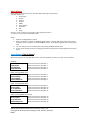
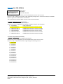
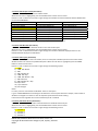
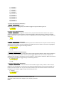
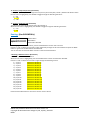
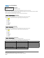
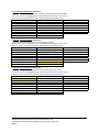
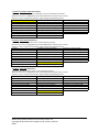
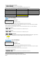
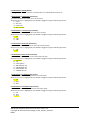
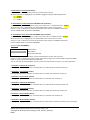
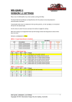
DMON-16S 1 to 16 Channel (3G/HD/SD)‐SDI Multi‐Viewer with SDI and HDMI outputs Operating Manual for Firmware Version 1.3 Introduction Thank you for purchasing the DMON‐16S 16 Channel (3G/HD/SD)‐SDI Multi‐Viewer with HDMI and SDI outputs. The DMON‐16S is a truly portable converter, which incorporates our new easy to use LCD and button control system. This gives you easy access to most of the amazing features that have been unavailable without a computer until now. The days of having to play with complicated dip switches or having to carry around a computer to change a simple setting are gone. The DMON‐16S features the following: Low cost miniature (3G/HD/SD)‐SDI 1 to 16 channel Multi‐Viewer or 16 to 1 input multiplexer Custom Layouts with various standard layouts 16 Character UMD overlay per window with individual enables, custom positioning and size 8 Channel Audio Metering overlay per window with individual enables, custom positioning and size Safe Action and Safe Title overlay per window with individual enables and adjustment Centre Cross overlay per window with individual enable Audio ID overlay Tallies can be applied to either Tally Boxes (Default), Outside Safe Action Area or Border Tally boxes allows for up to 4 Tallies per window with Tally Boxes (Green, Red, Blue and Yellow) Load and restore Custom Layouts Fast switching between inputs using Full‐Screen scaling Selectable output format in both Full‐Screen and Multi‐Viewer mode Low latency buffering for each input allowing non‐synchronous inputs Linked (3G/HD/SD)‐SDI and HDMI outputs 16 x (3G/HD/SD)‐SDI inputs with auto detection (26 Formats supported in total) Supports both 3G level A and B on the input and output Each window is independent of the others, allowing any 3G/HD/SD format of any frame rate to be displayed simultaneously Variable aspect ratios per window Pass‐Through mode allowing any of the 16 inputs to be selected for output In Pass‐Through mode the selected input is passed through to both the (3G/HD/SD)‐SDI and HDMI outputs The DMON‐16S is a truly portable converter that incorporates our new easy to use LCD and button control system. This gives you easy access to most of the amazing features without using complicated LED/button control, dip switches or having to carry around a computer to change a simple setting. This unit also includes: ‐ 32 GPI on 37‐pin D‐SUB connector for Dynamic Tallies and Remote Switching ‐ RS422/485 on 37‐pin D‐SUB connector for Dynamic UMD and Tallies via TSL protocol ‐ USB port for control and firmware updates ‐ Heavy duty metal box ‐ Metal Thread Locking DC Power Socket ‐ Power Supply, HDMI Cable and USB Cable DMON‐16S Hardware Manual for Firmware Version 1.3 Copyright © 2015 Decimator Design Pty Ltd, Sydney, Australia E&OE 1 Main Menus Upon power up the unit will start in the Main Menu pointing to Input Status. The Main Menus are: 1. Input Status 2. Control 3. Routing 4. Colours 5. UMDs 6. Audio Meters 7. Graticules 8. GPI 9. Setup Press the < and > buttons to move left or right through the menus. To enter into a menu press the ENTER button. Notes: 1. Defaults are highlighted in yellow. 2. When an option is changed, a highlighted S will appear in the top right of the LCD screen and will disappear when the options are saved after 10 seconds. Avoid powering down the unit during this time. 3. You can always return to the Main Menu by pressing the BACK button twice. 4. As you move through the menus changing parameters, they will be instantly applied to the output signal. Input Status: (Has 4 states) When pressing enter in the Input Status menu, will cycle between the status for input 1‐4, 5‐8 and 9‐12. (Default) 1:3GA 1080p59.94 Current format on SDI Input 1 2:HD 720p50 Current format on SDI Input 2 3:SD 480i59.94 Current format on SDI Input 3 Current format on SDI Input 4 4:HD 1080i59.94 (After pressing ENTER once) 5:3GA 1080p60 Current format on SDI Input 5 6:3GB 1080p50 Current format on SDI Input 6 7:3GA 1080p60 Current format on SDI Input 7 8:3GB 1080p59.94 Current format on SDI Input 8 (After pressing ENTER twice) 9:HD 1080p24 Current format on SDI Input 9 10:HD 720p50 Current format on SDI Input 10 11:SD 480i59.94 Current format on SDI Input 11 12:HD 1080i59.94 Current format on SDI Input 12 (After pressing ENTER three times) 13:SD 576i50 Current format on SDI Input 13 14:HD 720p24 Current format on SDI Input 14 15:SD 480i59.94 Current format on SDI Input 15 163GB 1080p59.94 Current format on SDI Input 16 DMON‐16S Hardware Manual for Firmware Version 1.3 Copyright © 2015 Decimator Design Pty Ltd, Sydney, Australia E&OE 2 Control: (Has SUB‐MENUs) Control HDMI Output Type HDMI RGB444 2C Main Menu <== Sub Menu Parameter Window When highlighted in the Main Menu, press the ENTER button to enter this sub‐menu. Press the < and > buttons to move left or right respectively through the 13 menus below and press the BACK button to go back to the Main Menu when finished. The current value for each Sub Menu is shown in the Parameter Window. 1. Control / HDMI Output Type (Parameter) This is the current HDMI output type for output 1. When the sub menu is highlighted, press ENTER to toggle through the following types: 1.) DVI RGB444 DVI‐D RGB 4:4:4 2.) HDMI RGB444 2C HDMI RGB 4:4:4 with 2‐Channels of Audio 3.) HDMI YCbCr444 2C HDMI YCbCr 4:4:4 with 2‐Channels of Audio 4.) HDMI YCbCr422 2C HDMI YCbCr 4:2:2 with 2‐Channels of Audio 5.) HDMI RGB444 8C HDMI RGB 4:4:4 with 8‐Channels of Audio HDMI YCbCr 4:4:4 with 8‐Channels of Audio 6.) HDMI YCbCr444 8C 7.) HDMI YCbCr422 8C HDMI YCbCr 4:2:2 with 8‐Channels of Audio 2. Control / Output Select (Parameter) This is the current source for the HDMI and SDI outputs. When the sub menu is highlighted, press the ENTER button to enter this sub‐menu. Press the < and > buttons to move left or right through the following sources: 1.) Multi‐View 2.) Window 1 3.) Window 2 4.) Window 3 5.) Window 4 6.) Window 5 7.) Window 6 8.) Window 7 9.) Window 8 10.) Window 9 11.) Window 10 12.) Window 11 13.) Window 12 14.) Window 13 15.) Window 14 16.) Window 15 17.) Window 16 DMON‐16S Hardware Manual for Firmware Version 1.3 Copyright © 2015 Decimator Design Pty Ltd, Sydney, Australia E&OE 3 3. Control / MV Output Format (Parameter) This is the current output format for the Multi‐Viewer. When the sub menu is highlighted, press the ENTER button to enter this sub‐menu. Press the < and > buttons to move left or right through the 26 video formats listed below and the BACK button to leave this SUB‐MENU. 1. SD 720x487i59.94 10. HD 1920x1080psf23.98 19. HD 1280x720p30 2. SD 720x576i50 11. HD 1920x1080p30 20. HD 1280x720p29.97 3. HD 1920x1080i60 12. HD 1920x1080p29.97 21. HD 1280x720p25 4. HD 1920x1080i59.94 13. HD 1920x1080p25 22. HD 1280x720p24 5. HD 1920x1080i50 14. HD 1920x1080p24 23. HD 1280x720p23.98 6. HD 1920x1080psf30 15. HD 1920x1080p23.98 24. 3G 1920x1080p60 7. HD 1920x1080psf29.97 16. HD 1280x720p60 25. 3G 1920x1080p59.94 8. HD 1920x1080psf25 17. HD 1280x720p59.94 26. 3G 1920x1080p50 9. HD 1920x1080psf24 18. HD 1280x720p50 Note: Currently we do not support HD 1280x720p24/23.98 on the HDMI output 4. Control / MV Windows (Parameter) This is the current number of windows shown on the multi‐view output. When the sub menu is highlighted, press the ENTER button to enter this sub‐menu. Press the < and > buttons to move left or right through the number of windows displayed from 1 to 16. Default Windows displayed is 16 windows. 5. Control / MV Layout (Parameter) This is the current layout of the multi‐viewer, there are 32 layouts selectable per format and multi‐viewer window number. 10 of these are predefined layouts. When the sub menu is highlighted, press the ENTER button to enter this sub‐menu. Press the < and > buttons to move left or right through the following layouts: 1.) 100% 2.) 100% with Border 3.) 90% 4.) 90% with Border 5.) 100% with Gap 6.) 100% with Border + Gap 7.) 90% with Gap 8.) 90% with Border + Gap 9 to 30) Custom 31.) Top to Bottom 32.) Left to Right Notes: For every ‘Format’ and ‘Number of Windows’ there are 32 layouts. E.g. for a 1920x1080i60 format showing 12 windows there are 32 layouts tied to this output, if the number of windows is changed to 11 there are also 32 separate layouts attached to this setting. Full Screen Pass through will also use the selected layout for 1 window. 6. Control / MV Audio Source (Parameter) This selects which window the audio is extracted from for the Multi‐Viewer output. When the sub menu is highlighted, press the ENTER button to enter this sub‐menu. Press the < and > buttons to move left or right through the following sources: 1.) Window 1 2.) Window 2 3.) Window 3 4.) Window 4 DMON‐16S Hardware Manual for Firmware Version 1.3 Copyright © 2015 Decimator Design Pty Ltd, Sydney, Australia E&OE 4 5.) Window 5 6.) Window 6 7.) Window 7 8.) Window 8 9.) Window 9 10.) Window 10 11.) Window 11 12.) Window 12 13.) Window 13 14.) Window 14 15.) Window 15 16.) Window 16 7. Control / MV Reference (Parameter) This is reference for the Multi‐Viewer. When the sub menu is highlighted, press ENTER to toggle through the following sources: 1.) Window 1 2.) Free‐Run 8. Control / Pass Scaled (Parameter) When the Output Select is changed to window 1 to 16, this parameter determines whether the output is scaled or passed through unchanged from the selected window. When the output is scaled, the selected layout for window 1 is used. When the sub menu is highlighted, press ENTER to toggle through the following selections: 1.) Yes 2.) No 9. Control / Format Status (Parameter) When an input is detected the DMON‐16S will display the format detected in the top left of each window by default unless the location has been modified via the USB Control Panel. When the sub menu is highlighted, press ENTER to toggle through the following selections: 1.) Show for 5 sec 2.) Show Always 3.) Off 10. Control / Audio Source ID (Parameter) The Audio Source Identification icon will appear when selecting which window the audio will be passed from to the output when in multi‐viewer mode. This option toggles whether the icon is shown to indicate the window source the audio is coming from. This icon appears in front of the Format Status. When the sub menu is highlighted, press ENTER to toggle through the following selections: 1.) Show for 5 sec 2.) Show Always 3.) Off 11. Control / Apply Tally to (Parameter) The Apply tally to parameter allows the selection of the 3 different types of tally indicators. When a tally is triggered it can be displayed as a small box on the bottom left (default position) of the inputs window or as border around the window. The Tally can also fill the outside of the safe action box. When the sub menu is highlighted, press ENTER to toggle through the following selections: 1.) Border 2.) Out Safe Action 3.) Tally Boxes DMON‐16S Hardware Manual for Firmware Version 1.3 Copyright © 2015 Decimator Design Pty Ltd, Sydney, Australia E&OE 5 12. Control / Tally Transparency (Parameter) The Tally transparency feature changes the transparency of the tally box / border / Outside safe Action. When the sub menu is highlighted, press ENTER to toggle through the following selections: 1.) 0% 2.) 25% 3.) 50% 13. Control / 3G Output is B (Parameter) This determines if the 3G‐SDI output level is B instead of A. When the sub menu is highlighted, press ENTER to toggle through the following selections: 1.) Yes 2.) No Routing: (Has SUB‐MENUs) Routing Window 1 Source Input 1 Main Menu <== Sub Menu Parameter Window When highlighted in the Main Menu, press the ENTER button to enter this sub‐menu. Press the < and > buttons to move left or right respectively through the 16 menus below and press the BACK button to go back to the Main Menu when finished. The current value for each Sub Menu is shown in the Parameter Window. 1. Routing / Window 1 Source (Parameter) This is the input source for Window 1. When the sub menu is highlighted, press the ENTER button to enter the Parameter Window. Press the < and > buttons to move left or right through the following sources: 1.) Input 1 (default for Window 1) 2.) Input 2 (default for Window 2) 3.) Input 3 (default for Window 3) 4.) Input 4 (default for Window 4) 5.) Input 5 (default for Window 5) 6.) Input 6 (default for Window 6) 7.) Input 7 (default for Window 7) 8.) Input 8 (default for Window 8) 9.) Input 9 (default for Window 9) 10.) Input 10 (default for Window 10) 11.) Input 11 (default for Window 11) 12.) Input 12 (default for Window 12) 13.) Input 13 (default for Window 13) 14.) Input 14 (default for Window 14) 15.) Input 15 (default for Window 15) 16.) Input 16 (default for Window 16) Please note that Windows 2 to 16 sources are the same as above. DMON‐16S Hardware Manual for Firmware Version 1.3 Copyright © 2015 Decimator Design Pty Ltd, Sydney, Australia E&OE 6 Colours: (Has SUB‐MENUs) Colours Background Color Black Main Menu <== Sub Menu Parameter Window When highlighted in the Main Menu, press the ENTER button to enter this sub‐menu. Press the < and > buttons to move left or right respectively through the 10 menus below and press the BACK button to go back to the Main Menu when finished. The current value for each Sub Menu is shown in the Parameter Window. 1. Colours / Background Colour (Parameter) This is background colour for the Multi‐Viewer. When the sub menu is highlighted, press the ENTER button to enter this sub‐menu. Press the < and > buttons to move left or right through the following colours: 1.) Black 2.) Blue 3.) Green 4.) Cyan 5.) Red 6.) Magenta 7.) Yellow 8.) White 2. Colours / Border Colour (Parameter) This is border colour for the Multi‐Viewer. When the sub menu is highlighted, press the ENTER button to enter this sub‐menu. Press the < and > buttons to move left or right through the following colours: 1.) Black 2.) Blue 3.) Green 4.) Cyan 5.) Red 6.) Magenta 7.) Yellow 8.) White 3. Colours / UMD Foreground (Parameter) This is the UMD colour and transparency setting for the text. When the sub menu is highlighted, press the ENTER button to enter this sub‐menu. Press the < and > buttons to move left or right through the following colours: 1. None 10. Black (Transparent 25%) 19. Blue (Transparent 0%) 2. Black (Transparent 50%) 11. Blue (Transparent 25%) 20. Green (Transparent 0%) 3. Blue (Transparent 50%) 12. Green (Transparent 25%) 21. Cyan (Transparent 0%) 4. Green (Transparent 50%) 13. Cyan (Transparent 25%) 22. Red (Transparent 0%) 5. Cyan (Transparent 50%) 14. Red (Transparent 25%) 23. Magenta (Transparent 0%) 6. Red (Transparent 50%) 15. Magenta (Transparent 25%) 24. Yellow (Transparent 0%) 7. Magenta (Transparent 50%) 16. Yellow (Transparent 25%) 25. White (Transparent 0%) 8. Yellow (Transparent 50%) 17. White (Transparent 25%) 9. White (Transparent 50%) 18. Black (Transparent 0%) DMON‐16S Hardware Manual for Firmware Version 1.3 Copyright © 2015 Decimator Design Pty Ltd, Sydney, Australia E&OE 7 4. Colours / UMD Background (Parameter) This is the UMD colour and transparency setting for the background of the UMDs. When the sub menu is highlighted, press the ENTER button to enter this sub‐menu. Press the < and > buttons to move left or right through the following colours: 1. None 10. Black (Transparent 25%) 19. Blue (Transparent 0%) 2. Black (Transparent 50%) 11. Blue (Transparent 25%) 20. Green (Transparent 0%) 3. Blue (Transparent 50%) 12. Green (Transparent 25%) 21. Cyan (Transparent 0%) 4. Green (Transparent 50%) 13. Cyan (Transparent 25%) 22. Red (Transparent 0%) 5. Cyan (Transparent 50%) 14. Red (Transparent 25%) 23. Magenta (Transparent 0%) 6. Red (Transparent 50%) 15. Magenta (Transparent 25%) 24. Yellow (Transparent 0%) 7. Magenta (Transparent 50%) 16. Yellow (Transparent 25%) 25. White (Transparent 0%) 8. Yellow (Transparent 50%) 17. White (Transparent 25%) 9. White (Transparent 50%) 18. Black (Transparent 0%) 5. Colours / Format ForeGrnd (Parameter) This is the Status Format text colour and transparency setting. When the sub menu is highlighted, press the ENTER button to enter this sub‐menu. Press the < and > buttons to move left or right through the following colours: 1. None 10. Black (Transparent 25%) 19. Blue (Transparent 0%) 2. Black (Transparent 50%) 11. Blue (Transparent 25%) 20. Green (Transparent 0%) 3. Blue (Transparent 50%) 12. Green (Transparent 25%) 21. Cyan (Transparent 0%) 4. Green (Transparent 50%) 13. Cyan (Transparent 25%) 22. Red (Transparent 0%) 5. Cyan (Transparent 50%) 14. Red (Transparent 25%) 23. Magenta (Transparent 0%) 6. Red (Transparent 50%) 15. Magenta (Transparent 25%) 24. Yellow (Transparent 0%) 7. Magenta (Transparent 50%) 16. Yellow (Transparent 25%) 25. White (Transparent 0%) 8. Yellow (Transparent 50%) 17. White (Transparent 25%) 9. White (Transparent 50%) 18. Black (Transparent 0%) 6. Colours / Format BackGrnd (Parameter) This is the Status Format text background colour and transparency setting. When the sub menu is highlighted, press the ENTER button to enter this sub‐menu. Press the < and > buttons to move left or right through the following colours: 1. None 10. Black (Transparent 25%) 19. Blue (Transparent 0%) 2. Black (Transparent 50%) 11. Blue (Transparent 25%) 20. Green (Transparent 0%) 3. Blue (Transparent 50%) 12. Green (Transparent 25%) 21. Cyan (Transparent 0%) 4. Green (Transparent 50%) 13. Cyan (Transparent 25%) 22. Red (Transparent 0%) 5. Cyan (Transparent 50%) 14. Red (Transparent 25%) 23. Magenta (Transparent 0%) 6. Red (Transparent 50%) 15. Magenta (Transparent 25%) 24. Yellow (Transparent 0%) 7. Magenta (Transparent 50%) 16. Yellow (Transparent 25%) 25. White (Transparent 0%) 8. Yellow (Transparent 50%) 17. White (Transparent 25%) 9. White (Transparent 50%) 18. Black (Transparent 0%) DMON‐16S Hardware Manual for Firmware Version 1.3 Copyright © 2015 Decimator Design Pty Ltd, Sydney, Australia E&OE 8 7. Colours / Outside S.Action (Parameter) This is the Colour and transparency setting for the area outside the safe action. When the sub menu is highlighted, press the ENTER button to enter this sub‐menu. Press the < and > buttons to move left or right through the following colours: 1. None 10. Black (Transparent 25%) 19. Blue (Transparent 0%) 2. Black (Transparent 50%) 11. Blue (Transparent 25%) 20. Green (Transparent 0%) 3. Blue (Transparent 50%) 12. Green (Transparent 25%) 21. Cyan (Transparent 0%) 4. Green (Transparent 50%) 13. Cyan (Transparent 25%) 22. Red (Transparent 0%) 5. Cyan (Transparent 50%) 14. Red (Transparent 25%) 23. Magenta (Transparent 0%) 6. Red (Transparent 50%) 15. Magenta (Transparent 25%) 24. Yellow (Transparent 0%) 7. Magenta (Transparent 50%) 16. Yellow (Transparent 25%) 25. White (Transparent 0%) 8. Yellow (Transparent 50%) 17. White (Transparent 25%) 9. White (Transparent 50%) 18. Black (Transparent 0%) 8. Colours / Safe Action (Parameter) This is the Safe Action graticule colour and transparency setting. When the sub menu is highlighted, press the ENTER button to enter this sub‐menu. Press the < and > buttons to move left or right through the following colours: 1. None 10. Black (Transparent 25%) 19. Blue (Transparent 0%) 2. Black (Transparent 50%) 11. Blue (Transparent 25%) 20. Green (Transparent 0%) 3. Blue (Transparent 50%) 12. Green (Transparent 25%) 21. Cyan (Transparent 0%) 4. Green (Transparent 50%) 13. Cyan (Transparent 25%) 22. Red (Transparent 0%) 5. Cyan (Transparent 50%) 14. Red (Transparent 25%) 23. Magenta (Transparent 0%) 6. Red (Transparent 50%) 15. Magenta (Transparent 25%) 24. Yellow (Transparent 0%) 7. Magenta (Transparent 50%) 16. Yellow (Transparent 25%) 25. White (Transparent 0%) 8. Yellow (Transparent 50%) 17. White (Transparent 25%) 9. White (Transparent 50%) 18. Black (Transparent 0%) 9. Colours / Safe Title (Parameter) This is the Safe Title graticule colour and transparency setting. When the sub menu is highlighted, press the ENTER button to enter this sub‐menu. Press the < and > buttons to move left or right through the following colours: 1. None 10. Black (Transparent 25%) 19. Blue (Transparent 0%) 2. Black (Transparent 50%) 11. Blue (Transparent 25%) 20. Green (Transparent 0%) 3. Blue (Transparent 50%) 12. Green (Transparent 25%) 21. Cyan (Transparent 0%) 4. Green (Transparent 50%) 13. Cyan (Transparent 25%) 22. Red (Transparent 0%) 5. Cyan (Transparent 50%) 14. Red (Transparent 25%) 23. Magenta (Transparent 0%) 6. Red (Transparent 50%) 15. Magenta (Transparent 25%) 24. Yellow (Transparent 0%) 7. Magenta (Transparent 50%) 16. Yellow (Transparent 25%) 25. White (Transparent 0%) 8. Yellow (Transparent 50%) 17. White (Transparent 25%) 9. White (Transparent 50%) 18. Black (Transparent 0%) DMON‐16S Hardware Manual for Firmware Version 1.3 Copyright © 2015 Decimator Design Pty Ltd, Sydney, Australia E&OE 9 10. Colours / Centre Cross (Parameter) This is the Centre Cross colour and transparency setting. When the sub menu is highlighted, press the ENTER button to enter this sub‐menu. Press the < and > buttons to move left or right through the following colours: 1. None 10. Black (Transparent 25%) 19. Blue (Transparent 0%) 2. Black (Transparent 50%) 11. Blue (Transparent 25%) 20. Green (Transparent 0%) 3. Blue (Transparent 50%) 12. Green (Transparent 25%) 21. Cyan (Transparent 0%) 4. Green (Transparent 50%) 13. Cyan (Transparent 25%) 22. Red (Transparent 0%) 5. Cyan (Transparent 50%) 14. Red (Transparent 25%) 23. Magenta (Transparent 0%) 6. Red (Transparent 50%) 15. Magenta (Transparent 25%) 24. Yellow (Transparent 0%) 7. Magenta (Transparent 50%) 16. Yellow (Transparent 25%) 25. White (Transparent 0%) 8. Yellow (Transparent 50%) 17. White (Transparent 25%) 9. White (Transparent 50%) 18. Black (Transparent 0%) UMDs: (Has SUB‐MENUs) UMDs All On Main Menu <== Sub Menu Parameter Window When highlighted in the Main Menu, press the ENTER button to enter this sub‐menu. Press the < and > buttons to move left or right respectively through the 3 menus below and press the BACK button to go back to the Main Menu when finished. The current value for each Sub Menu is shown in the Parameter Window, unless it is an action Sub Menu. 1. UMDs / All On (Action) Pressing ENTER when this submenu is selected will turn all UMD overlays on. 2. UMDs / All Off (Action) Pressing ENTER when this submenu is selected will turn all UMD overlays off. 3. UMDs / UMD Justify (Parameter) This parameter determines whether the text inside the 16 character window is centred, left or right justified. When the sub menu is highlighted, press ENTER to toggle through the following options: 1.) Centre 2.) Left 3.) Right Audio Meters: (Has SUB‐MENUs) Audio Meters All On Main Menu <== Sub Menu Parameter Window When highlighted in the Main Menu, press the ENTER button to enter this sub‐menu. Press the < and > buttons to move left or right respectively through the 11 menus below and press the BACK button to go back to the Main Menu when finished. The current value for each Sub Menu is shown in the Parameter Window. 1. Audio Meters / All On (Action) Pressing ENTER when this submenu is selected will turn all Audio Meter overlays on. DMON‐16S Hardware Manual for Firmware Version 1.3 Copyright © 2015 Decimator Design Pty Ltd, Sydney, Australia E&OE 10 2. Audio Meters / All Off (Action) Pressing ENTER when this submenu is selected will turn all Audio Meter overlays off. 3. Audio Meter / Combination (Parameter) This is the combination of either bar or float meters. When the sub menu is highlighted, press ENTER to toggle through the following selections: 1.) None 2.) Bar Only 3.) Float Only 4.) Bar and Float 4. Audio Meter / Transparency (Parameter) This is the transparency level of the audio meter overlays. When the sub menu is highlighted, press ENTER to toggle through the following selections: 1.) 0% 2.) 25% 3.) 50% 5. Audio Meter / Show Scale (Parameter) This indicates if the scale is shown on the audio meter overlays. When the sub menu is highlighted, press ENTER to toggle through the following selections: 1.) Off 2.) On 6. Audio Meter / Meter Scale (Parameter) This is the current scale shown on the audio meter overlays. When the sub menu is highlighted, press ENTER to toggle through the following selections: 1.) AES/EBU 2.) VU 3.) Extended VU 4.) BBC PPM (IEC 2a) 5.) EBU PPM (IEC 2b) 6.) DIN PPM (IEC 1a) 7.) NORDIC (IEC 1b) 7. Audio Meter / Bar Ballistics (Parameter) This is the current ballistics applied to the bar audio meter. When the sub menu is highlighted, press ENTER to toggle through the following selections: 1.) VU 2.) IEC1 3.) IEC2 8. Audio Meter / Float Ballistics (Parameter) This is the current ballistics applied to the float audio meter. When the sub menu is highlighted, press ENTER to toggle through the following selections: 1.) VU 2.) IEC1 3.) IEC2 DMON‐16S Hardware Manual for Firmware Version 1.3 Copyright © 2015 Decimator Design Pty Ltd, Sydney, Australia E&OE 11 9. Audio Meter / Ref Level (Parameter) This is the current audio reference level for the audio meter overlays. When the sub menu is highlighted, press ENTER to toggle through the following selections: 1.) ‐20 dBFS 2.) ‐18 dBFS 3.) ‐15 dBFS 10. Audio Meter / Yellow Start (Has SUB‐MENU with parameter) This is the starting level for the yellow range on the audio meter. The default value is ‐10dBFS. When the sub menu is highlighted, press the ENTER button to enter this sub‐menu. Press the < and > buttons to increase and decrease the level from 0 to ‐100dBFS respectively. Press the BACK button to leave this SUB‐MENU. 11. Audio Meter / Green Start (Has SUB‐MENU with parameter) This is the starting level for the green range on the audio meter. The default value is ‐20dBFS. When the sub menu is highlighted, press the ENTER button to enter this sub‐menu. Press the < and > buttons to increase and decrease the level from 0 to ‐100dBFS respectively. Press the BACK button to leave this SUB‐MENU. Graticules: (Has SUB‐MENUs) Graticules Main Menu <== S.Action All On Sub Menu Parameter Window When highlighted in the Main Menu, press the ENTER button to enter this sub‐menu. Press the < and > buttons to move left or right respectively through the 9 menus below and press the BACK button to go back to the Main Menu when finished. The current value for each Sub Menu is shown in the Parameter Window, unless it is an action Sub Menu. 1. Graticules / S.Action All On (Action) Pressing ENTER when this submenu is selected will turn all Safe Action Graticules overlays on. 2. Graticules / S.Title All On (Action) Pressing ENTER when this submenu is selected will turn all Safe Title Graticules overlays on. 3. Graticules / C.Cross All On (Action) Pressing ENTER when this submenu is selected will turn all Centre Cross overlays on. 4. Graticules / S.Action All Off (Action) Pressing ENTER when this submenu is selected will turn all Safe Action Graticules overlays off. 5. Graticules / S.Title All Off (Action) Pressing ENTER when this submenu is selected will turn all Safe Title Graticules overlays off. 6. Graticules / C.Cross All Off (Action) Pressing ENTER when this submenu is selected will turn all Centre Cross overlays off. 7. Graticules / All Anamorphic (Action) Pressing ENTER when this submenu is selected will set all Safe Action and Safe Tile Graticules to anamorphic. DMON‐16S Hardware Manual for Firmware Version 1.3 Copyright © 2015 Decimator Design Pty Ltd, Sydney, Australia E&OE 12 8. Graticules / All 16:9 LB (Action) Pressing ENTER when this submenu is selected will set all Safe Action and Safe Tile Graticules to 16:9 Letter Box on a 4:3 Raster. For use with 16:9 and HD/SD inputs being displayed on a 4:3 SD output. 9. Graticules / All 4:3 PB (Action) Pressing ENTER when this submenu is selected will set all Safe Action and Safe Tile Graticules to 4:3 Letter Box on a 16:9 Raster. For use with 4:3 SD inputs being displayed on a 16:9 HD/SD output. GPI: (Has SUB‐MENUs) GPI GPI Mode 00 Main Menu <== Sub Menu Parameter Window When highlighted in the Main Menu, press the ENTER button to enter this sub‐menu. When the sub menu is highlighted, press ENTER to toggle through the Modes and press the BACK button to go back to the Main Menu when finished. The current value for each Sub Menu is shown in the Parameter Window. GPI Mode = 00: PIN 1 = Ground PIN 14 = Window 7 Tally Red PIN 27 = Window 12 Tally Green PIN 2 = RS485+ PIN 15 = Window 9 Tally Red PIN 28 = Window 14 Tally Green PIN 3 = Window 1 Tally Green PIN 16 = Window 11 Tally Red PIN 29 = Window 16 Tally Green PIN 4 = Window 3 Tally Green PIN 17 = Window 13 Tally Red PIN 30 = Window 2 Tally Red PIN 5 = Window 5 Tally Green PIN 18 = Window 15 Tally Red PIN 31 = Window 4 Tally Red PIN 6 = Window 7 Tally Green PIN 19 = Ground PIN 32 = Window 6 Tally Red PIN 7 = Window 9 Tally Green PIN 20 = Ground PIN 33 = Window 8 Tally Red PIN 8 = Window 11 Tally Green PIN 21 = RS485‐ PIN 34 = Window 10 Tally Red PIN 9 = Window 13 Tally Green PIN 22 = Window 2 Tally Green PIN 35 = Window 12 Tally Red PIN 10 = Window 15 Tally Green PIN 23 = Window 4 Tally Green PIN 36 = Window 14 Tally Red PIN 11 = Window 1 Tally Red PIN 24 = Window 6 Tally Green PIN 37 = Window 16 Tally Red PIN 12 = Window 3 Tally Red PIN 25 = Window 8 Tally Green PIN 13 = Window 5 Tally Red PIN 26 = Window 10 Tally Green GPI Mode = 01: PIN 1 = Ground PIN 14 = Window 7 Tally Red PIN 27 = Window 12 Tally Green PIN 2 = RS485+ PIN 15 = Window 9 Tally Red PIN 28 = Window 14 Tally Green PIN 3 = Window 1 Tally Green PIN 16 = Window 11 Tally Red PIN 29 = Window 16 Tally Green PIN 4 = Window 3 Tally Green PIN 17 = Window 13 Tally Red PIN 30 = Window 2 Tally Red PIN 5 = Window 5 Tally Green PIN 18 = Window 15 Tally Red PIN 31 = Window 4 Tally Red PIN 6 = Window 7 Tally Green PIN 19 = Ground PIN 32 = Window 6 Tally Red PIN 7 = Window 9 Tally Green PIN 20 = Ground PIN 33 = Window 8 Tally Red PIN 8 = Window 11 Tally Green PIN 21 = RS485‐ PIN 34 = Window 10 Tally Red PIN 9 = Window 13 Tally Green PIN 22 = Window 2 Tally Green PIN 35 = Window 12 Tally Red PIN 10 = Window 15 Tally Green PIN 23 = Window 4 Tally Green PIN 36 = Window 14 Tally Red PIN 11 = Window 1 Tally Red PIN 24 = Window 6 Tally Green PIN 37 = Output Select Toggle PIN 12 = Window 3 Tally Red PIN 25 = Window 8 Tally Green PIN 13 = Window 5 Tally Red PIN 26 = Window 10 Tally Green DMON‐16S Hardware Manual for Firmware Version 1.3 Copyright © 2015 Decimator Design Pty Ltd, Sydney, Australia E&OE 13 GPI Mode = 02: PIN 1 = Ground PIN 2 = RS485+ PIN 3 = Window 1 Tally Green PIN 4 = Window 3 Tally Green PIN 5 = Window 5 Tally Green PIN 6 = Window 7 Tally Green PIN 7 = Window 9 Tally Green PIN 8 = Window 11 Tally Green PIN 9 = Window 13 Tally Green PIN 10 = Window 1 Select PIN 11 = Window 3 Select PIN 12 = Window 5 Select PIN 13 = Window 7 Select PIN 14 = Window 9 Select PIN 15 = Window 11 Select PIN 16 = Window 13 Select PIN 17 = Window 15 Select PIN 18 = Multi‐View Select PIN 19 = Ground PIN 20 = Ground PIN 21 = RS485‐ PIN 22 = Window 2 Tally Green PIN 23 = Window 4 Tally Green PIN 24 = Window 6 Tally Green PIN 25 = Window 8 Tally Green PIN 26 = Window 10 Tally Green PIN 27 = Window 12 Tally Green PIN 28 = Window 14 Tally Green PIN 29 = Window 2 Select PIN 30 = Window 4 Select PIN 31 = Window 6 Select PIN 32 = Window 8 Select PIN 33 = Window 10 Select PIN 34 = Window 12 Select PIN 35 = Window 14 Select PIN 36 = Window 16 Select PIN 37 = Output Select Toggle Setup: (Has SUB‐MENUs) Setup LOAD DEFAULTS Main Menu <== Sub Menu Parameter Window When highlighted in the Main Menu, press the ENTER button to enter this sub‐menu. Press the < and > buttons to move left or right respectively through the 6 menus below and press the BACK button to go back to the Main Menu when finished. The current value for each Sub Menu is shown in the Parameter Window, unless it is an action Sub Menu. 1. SETUP / LOAD DEFAULTS (Action) When highlighted in the Menu Window, press the ENTER button to load the default settings. The device will be reset to the Main Menu Input Status. 2. SETUP / LCD OFF TIME (Parameter) This is the time taken for the LCD light to turn off after the last button press. When the sub menu is highlighted, press ENTER to toggle through the following times: 1.) 5 seconds 2.) 15 seconds 3.) 30 seconds 4.) 1 minute 5.) 5 minutes 6.) 10 minutes 7.) 30 minutes 8.) Never 3. SETUP / BACK2STATUS TIME (Parameter) This is the time before the main menu is returned to Input Status after the last button press. When the sub menu is highlighted, press ENTER to toggle through the following times: 1.) 5 seconds 2.) 15 seconds 3.) 30 seconds 4.) 1 minute 5.) 5 minutes 6.) 10 minutes 7.) 30 minutes 8.) Never DMON‐16S Hardware Manual for Firmware Version 1.3 Copyright © 2015 Decimator Design Pty Ltd, Sydney, Australia E&OE 14 4. SETUP / AUTO SAVE (Parameter) This parameter will determine if any changes will be saved to memory when changes are made. When the sub menu is highlighted, press ENTER to toggle through the following selections: 1.) Yes 2.) No 5. SETUP / Demo Cycle (Parameter) The Demo cycle setting is used for cycling through multiple layouts, windows or inputs on a time delay. When the sub menu is highlighted, press the ENTER button to enter this sub‐menu. Press the < and > buttons to move left or right through the following cycle types: 1.) None 2.) Output Select 3.) MV Windows 4.) MV Layouts Note: The parameter will only be updated when leaving this sub‐menu. 6. SETUP / Demo Cycle Time (Parameter) The Demo Cycle Time determines the amount of time to elapse before cycling to the next item. When the sub menu is highlighted, press the ENTER button to enter this sub‐menu. Press the < and > buttons to move left or right through the time until the unit moves to the next item in the cycle. Default time is 10 Seconds, Maximum time is 256 Seconds Note: The parameter will only be updated when leaving this sub‐menu. SERVICE WARRANTY Decimator Design warrants that this product will be free from defects in materials and workmanship for a period of 36 months from the date of purchase. If this product proves to be defective within this warranty period, Decimator Design, at its discretion, will either repair the defective product without charge for parts and labour, or will provide a replacement product in exchange for the defective product. In order to service under this warranty, you the Customer, must notify Decimator Design of the defect before the expiration of the warranty period and make suitable arrangements for the performance of service. The Customer shall be responsible for packaging and shipping the defective product to a designated service centre nominated by Decimator Design, with shipping charges prepaid. Decimator Design shall pay for the return of the product to the Customer if the shipment is to a location within the country in which the Decimator Design service centre is located. The Customer shall be responsible for paying all shipping charges, insurance, duties, taxes, and any other charges for products returned to any other location. This warranty shall not apply to any defect, failure or damage caused by improper use or improper or inadequate maintenance and care. Decimator Design shall not be obligated to furnish service under this warranty a) to repair damage resulting from attempts by personnel other than Decimator Design representatives to install, repair or service the product, b) to repair damage resulting from improper use or connection to incompatible equipment, c) to repair any damage or malfunction caused by the use of non‐ Decimator Design parts or supplies, or d) to service a product that has been modified or integrated with other products when the effect of such a modification or integration increases the time of difficulty of servicing the product. DMON‐16S Hardware Manual for Firmware Version 1.3 Copyright © 2015 Decimator Design Pty Ltd, Sydney, Australia E&OE 15