1
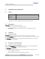
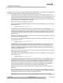
User Manual
For Marconi
Planet EV®
<1.1>
REF: RP/WAVECALL/24-03-2004/KR
Abstract
This document describes the installation and usage of the propagation
model WaveSight inside Marconi Planet EV. It is providing technical
information about the data and parameters required by WaveSight.
WaveSight User Manual Planet EV
Company Information
Address
Lausanne
Wavecall SA
Science Park of the
Swiss Institute of Technology
PSE-B / EPFL
1015 Lausanne
Phone +41 21 693 84 05
Fax
+41 21 693 84 06
Contact
Karim Rizk
Email
Web
[email protected]
http://www.wavecall.com
Document History
Version
Revision
Date
0.9
Karim Rizk
October 16, 2003
0.9.1
Karim Rizk
October 19, 2003
0.9.2
Karim Rizk
October 20, 2003
1.0
Karim Rizk
November 20, 2003
1.2
Odeh Ghawi
February 02, 2004
1.3
Jürgen Eitle
March 10, 2004
1.4
Jürgen Eitle
March 11, 2004
1.5
Jürgen Eitle
March 24, 2004
1.6
Jürgen Eitle
May 17, 2004
1.7
Jürgen Eitle
June 2, 2004
1.8
Jürgen Eitle
June 3, 2004
1.9
Jürgen Eitle
July 28, 2004
Confidential
© 2003 Wavecall SA
Jul-04 - Page 2/2
WaveSight User Manual Planet EV
REF: RP/WAVECALL/24-03-2004/KR.................................................................................................. 1
Company Information........................................................................................................................ 2
Document History .............................................................................................................................. 2
New Features of WaveSight for version 4.0 of Planet EV.................................................................. 4
1.
Introduction ................................................................................................................................. 4
2.
Installation and configuration.................................................................................................... 5
2.1
Version ..................................................................................................................................... 5
2.2
Prerequisites ............................................................................................................................ 5
2.3
Installation ............................................................................................................................... 5
2.3.1
2.4
Installation procedure...................................................................................................... 5
Parameters used by WaveSight............................................................................................. 5
2.4.1
Parameters to be set for WaveSight .............................................................................. 5
2.4.2
Parameters read by WaveSight from the transmitter settings.................................. 11
2.5
Vector data (buildings and vegetation) ............................................................................... 14
2.5.1
Configuring the data...................................................................................................... 14
2.5.2
Data requirements ......................................................................................................... 14
2.5.3
Vector data format ......................................................................................................... 17
2.5.4 Shape data format:.............................................................................................................. 19
2.6
Terrain data............................................................................................................................ 20
2.6.1 Digital Terrain Height Data (DTM) ......................................................................................... 20
2.7
3.
Running WaveSight .............................................................................................................. 20
WaveTune.................................................................................................................................. 22
3.1 Introduction ................................................................................................................................ 22
3.2 Running WaveTune ................................................................................................................... 22
3.3 Different optimization goals can be achieved with WaveTune ............................................ 28
4.
Frequently asked questions for Planet EV.............................................................................. 29
4.
Appendix I ................................................................................................................................. 29
(WaveSight error messages) .......................................................................................................... 29
5.
Bibliography .............................................................................................................................. 32
Confidential
© 2003 Wavecall SA
Jul-04 - Page 3/3
WaveSight User Manual Planet EV
New Features of WaveSight for version 4.0 of Planet EV
WaveSight is now supporting non co-located sectors, i. e. sites where the sector
antennas are not all at the same location. See section 2.4.2 for more information.
WaveSight can now directly read the the grid file from the project directory. As a result
a set of DTM files is obtained. See section 2.6 for more information.
WaveSight works without the user having selected a clutter. See section 2.4.1
WaveSight can read “shape data” building files. See section 2.5.4 for more information.
WaveTune is now available as a tuning model for WaveSight. See section 3. for more
information.
1.
Introduction
WaveSight is a wave propagation prediction tool for wireless networks. It is specifically used to
predict radio wave propagation for mobile communication networks in urban and suburban
environments.
The deployment of a cellular network is subject to tight schedules that must ensure high quality
service with optimal infrastructure expenditure. WaveSight is instrumental in reducing costs
and planning time, and in improving network quality as it meets prediction accuracy
requirements.
To achieve high prediction accuracy WaveSight uses new methods of calculation that were
validated as part of thesis research conducted at the Swiss Institute of Technology in Lausanne
(EPFL), Swisscom, Dutch Telecom and at Bell Laboratories of Lucent Technologies, Crawford
Hill, New Jersey, USA.
The inputs for WaveSight 3.6 are 1) the vector of buildings and vegetation (in case available),
terrain and clutter given in raster format.
Confidential
© 2003 Wavecall SA
Jul-04 - Page 4/4
WaveSight User Manual Planet EV
2.
Installation and configuration
2.1
Version
Component
Version information
WaveSight
algorithm
3.6
Interface
1.1.9.0 (with Planet EV 4.0.1)
Licensing of this release is integrated in Planet EV's licensing scheme.
2.2
Prerequisites
WaveSight requires the following environment:
1. Planet EV 4.0 or higher on Windows 2000 or higher.
2. Up to 500 MB of disk space for temporary files and >= 500 MB of RAM, 1 GB is
recommended.
2.3
Installation
2.3.1
Installation procedure
WaveSight comes pre-installed with Planet EV, contact Planet EV support for details.
To check if WaveSight is installed correctly, the following paragraphs give a brief overview over
the installed WaveSight files:
The WaveSight installation directory is by default "Planet EV install directory". It contains the
files "wavesight.exe", " ant_db.dat".
2.4
Parameters used by WaveSight
2.4.1
Parameters to be set for WaveSight
You can add a WaveSight model from Planet EV from the menu Tools->Propagation Model
Editor by selecting WaveSight in the Model Type choice list.
The WaveSight parameters are:
A) In the window Propagation Model Editor you can set the following parameters (Figure 1)
•
Frequency [MHz]: The frequency
•
Receiver Height [m]: The receiver height above the ground.
Confidential
© 2003 Wavecall SA
Jul-04 - Page 5/5
WaveSight User Manual Planet EV
B) When clicking on Edit in the window Propagation Model Editor a window named WaveSight
Parameters appears (Figure 2). The following parameters can be set:
•
Indoor Attenuation Factor [dB]: A penetration loss factor from outdoor to indoor. For
indoor calculations, WaveSight Computes the average field on the circumference of the
building and then applies a constant penetration loss. In general, we recommend the
following values for penetration loss: concrete walls (with windows): 10-15 dB, wooden
walls: 7 dB, metallic shielded glass: 20-40 dB
•
Resolution [m]: The computation resolution.
•
Corr. Factor Vertical [dB]: WaveSight translates this factor to a Medium Loss using the
following formula:
o
-
Medium Loss = 10 Corr. Factor Vertical/10.
The Medium Loss represents an attenuation associated with a ray propagating in the
vertical plane over buildings. This attenuation acts as the real part of the wave number.
The higher the real part of the wave number the higher is the Medium Loss. Therefore
according to the equation above the smaller the Corr. Factor Vertical the higher is the
Medium Loss.
This factor can be used to account for loss due to objects not represented in or missing
from the geographical database.
•
Corr. Factor Horizontal [dB]: WaveSight translates this factor to a Medium Loss using
the following formula:
o
-
Medium Loss = 10 Corr. Factor Horizontal/10
The Medium Loss represents an attenuation associated with a ray propagating in the
horizontal plane around buildings. This attenuation acts as the real part of the wave
number. The higher the real part of the wave number the higher is the Medium Loss.
Therefore according to the equation above the smaller the Corr. Factor Horizontal the
higher is the Medium Loss.
This factor can be used to account for loss due to objects not represented in or missing
from the geographical database.
•
Corr. Factor Terrain [dB]: WaveSight translates this factor to a Medium Loss using the
following formula:
o
-
Medium Loss = 10 Corr. Factor Terrain/10.
The Medium Loss represents an attenuation associated with a ray propagating in the
vertical plane after diffraction from terrain (typically in open areas). This factor is only
taken into account if there is no clutter associated with the point of diffraction. This
attenuation acts as the real part of the wave number. The higher the real part of the
wave number the higher is the Medium Loss. Therefore according to the equation
above the smaller the Corr. Factor Terrain the higher is the Medium Loss.
This factor can be used to account for terrain occupation when no clutter values are
available.
•
Terrain file path: It contains the path for the terrain directory that contains the terrain
data in format explained in section 2.6. Click on the Browse button adjacent to this field,
and select the index.txt files associated with the terrain data.
•
Building data path: It contains the path for the building directory that contains the
building and the vegetation data in format explained in section 2.5. Click on the Browse
Confidential
© 2003 Wavecall SA
Jul-04 - Page 6/6
WaveSight User Manual Planet EV
button adjacent to this field, and select the index.txt files associated with the vector
data.
•
Height Relative to Ground: Check this box to indicate that vector elevation data pointed
to by Vector data path is relative to ground level, otherwise they will be considered as
relative to sea level.
C) If the user has chosen to use clutter, then under the tab Clutter Properties in the Model Editor
the user must select Depend on Projects Settings. A Clutter Property Assignment (.cpa) file,
which is compatible with the clutter file, must be selected in the field Clutter Property
Assignment File. Click on the Edit CPA button to adjust the value of the clutter as follows
(Figure 3).
•
Permittivity: Is the relative permittivity assigned to the clutter. The permittivity is taken
into account in the diffraction formula over the terrain. The higher the permittivity is the
more energy is diffracted from the terrain
•
Conductivity [S/m]: Is the conductivity assigned to the clutter. The conductivity is taken
into account in the diffraction formula over the terrain. The higher the conductivity is
the more energy is diffracted from the terrain
•
Corr. Factor [dB]: represents attenuation associated with a ray propagating in the
vertical plane in open area above certain clutter.
In this version of the interface
The feature Use Single Clutter Property is not supported.
The two tabs Rain Attenuation and Advanced in Model Editor Window (Figure
1) are not considered
WaveSight does not consider the first row of the clutter, which is usually named
dBP_Unknown.
The higher the Corr. Factors (Vertical, Horizontal, Terrain, and in the clutter properties)
the lower is the resulting attenuation.
.
Confidential
© 2003 Wavecall SA
Jul-04 - Page 7/7
WaveSight User Manual Planet EV
Figure 1 WaveSight propagation model main menu
Figure 2 WaveSight parameters window
Confidential
© 2003 Wavecall SA
Jul-04 - Page 8/8
WaveSight User Manual Planet EV
Figure 3 Clutter Property Assignments
Once you have adjusted your properties you can open the Clutter Assignments tab
(see the Options menu). Here you should check, that all clutter properties from the .grc
file have been assigned. This means that all entries in the clutter list (left side in Figure
4) are checked.
At the same time make sure the number of entries in both lists is the same. If the
reference list has more entries than the clutter list. WaveSight and WaveTune may
produce unpredictable results or may not run at all. This usually is not an issue, as any
clutter reference list, that is automatically generated will have the correct number of
entries.
Confidential
© 2003 Wavecall SA
Jul-04 - Page 9/9
WaveSight User Manual Planet EV
Figure 4: Clutter Assignment, advanced
Confidential
© 2003 Wavecall SA
Jul-04 - Page 10/10
WaveSight User Manual Planet EV
2.4.2
Parameters read by WaveSight from the transmitter settings
From the main page (Figure 5)
•
The sector location coordinates X, Y for each sector. Note, that if all the sectors are
located at the same place, then this is equivalent to “site location” of earlier editions of
the interface. The interface now supports non co-located sectors. It is now possible for
one site to have its antennas at different locations.
From the Edit Sector (Figure 6)
•
EIRP (dBm): The equivalent isotropic radiated power (EIRP) in dBm
•
Antenna type: The antenna pattern
•
Height (m): The antenna height in meters
•
Azimuth: The antenna azimuth in degrees
•
Down-tilt: The antenna down tilt in degrees
•
Distance: Half the size of the square of the prediction frame
•
Propagation Model: The WaveSight propagation model
-
Confidential
WaveSight is only generating masked propagation predictions.
Therefore the user must check “prediction parameters by sector“ in
the site editor window (Figure 5)
© 2003 Wavecall SA
Jul-04 - Page 11/11
WaveSight User Manual Planet EV
Figure 5 Site Editor
Confidential
© 2003 Wavecall SA
Jul-04 - Page 12/12
WaveSight User Manual Planet EV
Figure 6 Sector editor
Confidential
© 2003 Wavecall SA
Jul-04 - Page 13/13
WaveSight User Manual Planet EV
2.5
Vector data (buildings and vegetation)
2.5.1
Configuring the data
Vector data is stored in ASCII format and requires three types of input files - a vector data file,
an attributes file and an index file. The index file has to be named “index.txt”. Each line is
containing: a vector data file name, an attribute file name, Easting Northing co-ordinates
representing a bounding box around that feature and the feature name itself (7 items). Lines
containing features without an attribute file are not accepted.
2.5.2
Data requirements
The building data used by WaveSight is modeling the buildings’ footprint and the
buildings’ height. The building data should comply with the following requirements:
Confidential
Requirement
Explanation
Identical polygons are not
accepted
The data set must not contain the same
building twice. This is the very idea of a set.
Polygons must be closed. The first
and the last point in each polygon
must be identical.
Open "polygons" are not accepted:
At least 3 distinct vertices per
polygon. Also the three vertices
must not be on a straight line.
The dataset must not contain one or two
coordinate "buildings".
One vertex must belong to
exactly two walls
This requirement means that
"Spikes" (the building outline contains a
vertex which comes back on a previous
vertex) are not permitted in the outline:
© 2003 Wavecall SA
Jul-04 - Page 14/14
WaveSight User Manual Planet EV
"8-shaped buildings" (the building outline
actually contains two buildings, touching
each other at one coordinate) are not
permitted:
Each two walls can only intersect
if they are successive walls
belonging to the same polygons.
In such a case the intersection
forms the vertex.
Confidential
This means that
Self-intersecting polygons are not allowed.
© 2003 Wavecall SA
Jul-04 - Page 15/15
WaveSight User Manual Planet EV
Overlapping polygons are not allowed:
All heights must be above local
ground.
It is not permitted to model "holes" as
buildings below the terrain height level.
An accuracy 1 m in building
corner position is required
The paper [2] contains a discussion of the
influence of the database accuracy on
prediction results. It is available on
Wavecall's web site.
There should not be any repeated
vertices.
This restriction applies to the versions before
2.2.19 of the WaveSight algorithm.
The index file must contain the
string "building" or vegetation
It is important to set the frame
coordinates correctly in the file
index.txt
Confidential
WaveSight is only reading buildings inside
these coordinates.
© 2003 Wavecall SA
Jul-04 - Page 16/16
WaveSight User Manual Planet EV
2.5.3
Vector data format
An example of the buildings or vegetation format, with all conditions as indicated above, is
shown below:
Vector file
Header Record
Easting
Northing
Easting
Northing
Easting
Northing
Easting
Northing
Easting
Northing
Header Record
Easting
Northing
Easting
Northing
Easting
Northing
The final row is terminated by a carriage return.
The format of the header record is as follows:
Field
Position
Description
1
1-5
Record Identifier (used to identify building segment in attributes file)
2
6-15
Blanks
3
16-47
32 Character description (not used, same as feature name field in index file entry)
4
48-50
Blanks
5
51-55
Record Count
00001
buildings
00005
725777.00 5031472.00
725775.00 5031468.00
725778.00 5031467.00
725780.00 5031471.00
725777.00 5031472.00
00002
buildings
00005
725783.00 5031472.00
725781.00 5031468.00
........
Confidential
© 2003 Wavecall SA
Jul-04 - Page 17/17
WaveSight User Manual Planet EV
The final row is terminated by a carriage return.
Vector Index File
An ASCII text file called index.txt contains positional information about the vector file. This file
must be in the same directory as the vector data.
Each row contains the following variables separated by a space:
Field
Description
Data filename
Filename of vector data file
Attribute filename
Filename of building attributes (heights) file
Eastmin
Minimum Easting value (meters)
Eastmax
Maximum Easting value (meters)
Northmin
Minimum Northing value (meters)
Northmax
Maximum Northing value (meters)
Feature Name
Name of the feature stored in the vector data file, for WaveSight
this name must contain a string called either “building” or
“vegetation”
For example:
buildings_vec.txt buildings_atr.txt 1627764 1630022 6579401 6582574 buildings
The final row is terminated by a carriage return.
Vector Attributes File
An ASCII text file, named in the index file contains height information about the building
segments contained in the vector data file.
Each row contains a record, as follows:
Field
Position
Description
1
1-5
Record Identifier (used to identify building segment in vector data
file)
2
6
Delimiter <space>
3
7-19
12 Character vector segment description (not used)
4
20
Delimiter <space>
5
21-26
Vector segment height (floating point, two decimal places)
Confidential
© 2003 Wavecall SA
Jul-04 - Page 18/18
WaveSight User Manual Planet EV
00001 buildings
010.00
00002 buildings
007.00
00003 buildings
011.00
00004 buildings
010.00
00005 buildings
006.00
00006 buildings
006.00
....
2.5.4 Shape data format:
The data should be available in ESRI Shape file format. There can be multiple Shape building
vector layers, which are referenced by an index.txt file in the following way:
Field
Description
Shape filename
Filename of the shape data file
Attribute name
The attributes name (inside the DBF file)
Eastmin
Minimum Easting value (meters)
Northmin
Minimum Northing value (meters)
Eastmax
Maximum Easting value (meters)
Northmax
Maximum Northing value (meters)
Note:
Please note that the sequence of the frame area of the buildings
in the index file is different from the one in vector file format.
Every Shape data set (shp, shx and dbf files) take one line in the index.txt line.
The first entry specifies the name of the Shape file; the second entry contains the name of the
attribute inside the DBF file containing the height of the building. The following entries contain
the bounding frame xmin ymin xmax ymax coordinates.
Confidential
© 2003 Wavecall SA
Jul-04 - Page 19/19
WaveSight User Manual Planet EV
2.6
Terrain data
There are two ways to specify input files for terrain data. If you leave blank the “Elevation grid
file” line in the “Analyisis->Project Settings” window, then a set of DTM files will automatically
be created. Otherwise the specified elevation file will be used.
2.6.1 Digital Terrain Height Data (DTM)
The digital terrain height data (DTM) needed is stored in a binary format where each element of
the data represents the height above sea level in meters for a square area of, for example, 50m
x 50m. Each element is two bytes in size and the most significant byte is stored first.
The elements are stored in one continuous array such that the size of the array in the following
example would be 500 (wide) x 500 (high) x 2 (bytes per element) = 500,000 bytes.
If there are pixels within the file that are outside the limits of the map, the value -9999 is stored
at that location.
An ASCII text file called index.txt contains positional information about each binary height file.
This file must be in the same directory as the height data.
The file contains one row describing each height file. Each row contains the following variables
separated by a space:
Field
Description
Filename
Filename of DTM Height file
Eastmin
Minimum Easting value (meters)
Eastmax
Maximum Easting value (meters)
Northmin
Minimum Northing value (meters)
Northmax
Maximum Northing value (meters)
Square Size
Size of each element of the height data (meters)
For example:
file1.bin
100000 125000 50000 75000 50
file2.bin
125000 150000 50000 75000 50
The final row is terminated by a carriage return.
In certain cases the Terrain data is available in several resolutions: typically a
resolution of 20+ for an entire state or nation, and 5m for built up areas. In such areas
the resolution that will be considered by WaveSight is the one associated with the
entry that comes last in the index file. Therefore it is recommended in the index file to
first list the lower resolution data and then the higher resolution ones.
2.7
Running WaveSight
Running WaveSight is following the same procedures as running any other prediction
tool in Planet EV.
Confidential
© 2003 Wavecall SA
Jul-04 - Page 20/20
WaveSight User Manual Planet EV
Each time WaveSight is called a log file named wsanalysis.err is generated. It is
located in project directory. The main use of this file is to track WaveSight errors
whenever they occur. This file was particularly designed to run WaveSight over a large
number of sites. In case WaveSight encounters an error on one sector:
Confidential
-
It will log the error to wsanalysis.err
-
A message in the Generator window will prompt the user to look at the log file
-
The predictions are carried out on the remaining sectors.
© 2003 Wavecall SA
Jul-04 - Page 21/21
WaveSight User Manual Planet EV
3.
WaveTune
3.1 Introduction
Planet EV is offering a model tuning feature. Here the term model tuning means the
process of adjusting the parameters of the WaveSight model in order to produce
predictions that are as accurate and realistic as possible. The tuning is usually
performed using measured signal strength data collected during surveys. The
parameters adjusted in this way are generally the clutter absorption loss values, the
Corr. Factor Vertical, the Corr. Factor Horizontal, and the Corr. Factor Terrain.
3.2 Running WaveTune
If you are new to model tuning please read the corresponding entries in Planet EV’s
help system. The following lines assume, that you are familiar with the basic
functionalities of Planet EV concerning model tuning. Follwing is a step by step
description of how to set up a WaveTune session from within Planet EV.
Before you start using the tuning capabilities make sure to create a C:\temp directory
(i. e. a directory named “temp” on the C: drive). WaveTune needs this directory being
present, otherwise it won’t run.
1.
In the project explorer open two windows. In one window chose the category
Sites and in the other chose the category Operational Data. In the Sites window
expand the sites you want to apply tuning to, and in the other expand the Surveys
(under Survey Manager, and the Surveys RSSI entry or whatever surveys you are
using). At the end of this step your Project explorer should look like in Figure 7. In our
example let’s tune sector 1 of site 1001 using survey survey_1001_1_ptp.
Confidential
© 2003 Wavecall SA
Jul-04 - Page 22/22
WaveSight User Manual Planet EV
Figure 7: Project explorer
2.
Right click on the survey you want to tune, and from the pop up menu choose
Model Tuning. When you are done you should have the Model Tuning window on
the screen.
In the Model to tune line choose the .dpm file corresponding to the WaveSight
Model you want to tune. Typically this would be the same name that you used to run
predictions on the corresponding sector.
In the Model tuner line WaveTune is automatically chosen as the model tuner.
In the New Model name enter the name of the model that is defined by the parameters
resulting from tuning the model chosen in step a.
In our example the Model to tune is WaveSight_tune, and the New Model name is
Confidential
© 2003 Wavecall SA
Jul-04 - Page 23/23
WaveSight User Manual Planet EV
WaveSight_adjusted. The process will create a new model file called
WaveSight_adjusted.dpm and a clutter assignment file called
WaveSight_adjusted.cpa.
Press Edit Tuner to open the WaveTune Parameters window.
3.
In the WaveTune Parameters window (Figure 8)
4.
Figure 8: WaveTune Parameters window
the initial values for the vertical, horizontal and terrain correction factors can be
entered. The increments have a fixed value, and cannot be edited by the user. You can
choose which value to include in tuning by simply checking or un-checking the
corresponding box in the Select column.
If you want to include clutter in the tuning process, you have to check the Use
Clutter Tuning check box. Then press the Edit Clutter button. This opens the
Confidential
© 2003 Wavecall SA
Jul-04 - Page 24/24
WaveSight User Manual Planet EV
Clutter Tuning Parameters Window. This window looks like this:
Figure 9: Clutter Tuning Parameters
After setting the clutter parameters, press OK to close the clutter window, then press
OK to close the WaveTune parameters window and finally press OK to start the tuning
process. Important: Do not use the unclassified_sat clutter, it will be ignored.
5.
At this point two windows will open and WaveTune will start to run. One
window is just indicating which model is being tuned and the total time elapsed since
the the start of the tuning process (Figure 10). Do not use the Cancel button in this
window to stop the tuning process. It will close the window, but not actually stop the
tuning process. See the next paragraph on how to properly abort tuning.
In the other window you will see print outs of WaveTune progressing (Figure 11). On
each iteration WaveTune indicates the current error value, and the last “best error”
value. If a new “best error” value is found, then this will be indicated. In order to abort
the tuning process, press the STOP button.
Confidential
© 2003 Wavecall SA
Jul-04 - Page 25/25
WaveSight User Manual Planet EV
Figure 10: Tuning progress
Confidential
© 2003 Wavecall SA
Jul-04 - Page 26/26
WaveSight User Manual Planet EV
Figure 11: WaveTune progress
In order to abort the tuning process, press the STOP button.
At the end of the tuning process the window will stay open. You will notice when the
program is finished, if you see several lines that show values for Airloss etc.
In the latter press the Close button, you will be prompted for viewing the tuning
report. It is important, that you stick to this sequence, as otherwise you will not see
the tuning report.
6.
After tuning a new propagation model file WaveSight_adjusted.dpm and a
new clutter assignment file WaveSight_adjusted.cpa is created. You can now use
this new model to run predictions. To do so in the Site Editor simply choose the
WaveSight_Adjusted.dpm as new propagation model for the sector you want to use
it on.
Confidential
© 2003 Wavecall SA
Jul-04 - Page 27/27
WaveSight User Manual Planet EV
3.3 Different optimization goals can be achieved with WaveTune
WaveTune is offering a great deal of flexibility in achieving your tuning goals.
Basically any one parameter can be included or excluded from the tuning process.
This way you can reduce calculation time, and also include your knowledge of the
propagation environment. Particularly the user can choose if the tuning should mainly
concentrate on reducing the standard deviation or the mean error or both at the same
time. Clutter can be included or excluded depending on whether you have a clutter file
or not. Different clutter properties can be included in the tuning or left at their original
value. This gives you the possibility to literally fine tune your model.
If you are new to model tuning with WaveTune, then here are some
recommendations:
1. Use RMS as the tuning option (cf. Figure 8)
Tuning options explained: On every iteration WaveTune is comparing the prediction
with the measured values. The error is characterized by two numbers, the arithmetic
mean of the error and the standard deviation (std) of the error. These two numbers
can be combined to form the root mean square (rms) of the error. The following
relation holds: rms2 = std2 + mean2. For the tuning process this means:
•
Use the RMS minimizing option to take into account the mean of the error,
and the standard deviation of the error. This is the recommended option.
•
Use the MEAN option, if you just want to minimize the mean of the error.
Using this option WaveTune disregards the standard deviation.
•
Use the STD option if you just want to minimize the standard deviation of the
error. Using this option WaveTune disregards the mean.
2. Chose all the correction factors (cf. Figure 8). Chose either the default values to
obtain fast convergence or the values, that correspond to the model you start with.
The correction factors have the following meaning:
•
Corr. Factor Vertical represents an attenuation associated with a ray
propagating in the vertical plane over buildings. It significantly influences
propagation in built up areas.
•
Corr. Factor Horizontal represents an attenuation associated with the
ray propagating in the horizontal plane, mainly for propagation around
buildings.
•
Corr. Factor Terrain represents an attenuation associated with the ray
propagating in the vertical plane over terrain. It significantly influences
propagation in open areas
3. Use the minimum number of clutter properties(cf. Figure 9). This means that you
should try to get as much information as you can get on the clutter properties, and
assign them in the WaveSight_tune.dpm file (the model file before tuning). The
more clutter you select for tuning, the longer the tuning process will take. On a 1.5
GHz Pentium 4 machine a survey route with 1000 points an area of 4 km2, and a
resolution of 50m might run for 5 hours to tune the three correction factors and one
clutter property.
A good way to choose the clutter to tune is to open the survey in the Survey to
Grid comparison window. Chose only those clutter types that have a nonzero
number of points. You can further reduce the number of clutter classes to tune by
obtaining local knowledge. E.g. water in your area has a known absorption factor, so
does concrete etc.
Note: WaveTune is directly using the clutter grid of Planet EV.
Confidential
© 2003 Wavecall SA
Jul-04 - Page 28/28
WaveSight User Manual Planet EV
Important: There is a limit of 14 different clutter properties that are simultaneously
tunable. This limit is there to keep computation times reasonable. Usually there are
no more than about 10 different clutter types in the area you want to tune. This limit
is also there to guide the user to a sensitive approach to tuning.
4. In dense urban areas, do not use clutter tuning, i. e. uncheck the Clutter
Tuning checkbox (cf. Figure 8).
In open non-urban areas, just use clutter tuning and do not select the Corr. factors.
In a transition zone you would have to use both.
4.
Frequently asked questions for Planet EV
Question
Answer
Question
Answer
Is the DTM format identical to the Planet format, i.e. the first element in
the file corresponds the Northwest corner and the last element to the
Southeast corner and the elements are ordered west to east?
Yes.
Question
Answer
What value should I use for the rain attenuation?
WaveSight do not use this parameter in Planet EV.
Question
What is the advantage of using Planet DMS format for the terrain data
and not Planet EV format?
The Planet EV format for the terrain data allow a maximum of two
different terrain resolutions; while using the DMS format for WaveSight
allows to use unlimited number of different resolutions.
Answer
4.
Is there a way to specify a specific index file in the Planet EV
propagation model editor, edit, browse for index file path?
WaveSight will only read the index.txt file and not care about the
others.
Appendix I
(WaveSight error messages)
Errors
WSERR1: You cannot have an
IndexTerrDir and a TerrainFile.
Please check infiles.txt
Confidential
Explanations
IndexTerrDir is a key word in infiles.txt that
indicates the directory of a specific type of
terrain format.
© 2003 Wavecall SA
Jul-04 - Page 29/29
WaveSight User Manual Planet EV
TerrainFile is a key word in infiles.txt that indicates
the path for the file WaveSight type of terrain.
Therefore it is not possible to have both
keywords in infiles.txt
IndexBldgDir is a key word in infiles.txt that
indicates the directory of specific type of
building format.
WSERR2: You cannot have an
IndexBldgDir and a BldgFile.
Please check the inputs.txt file
BldgFile is a key word in infiles.txt that
indicates the path for the file WaveSight
format of buildings.
Therefore it is not possible to have both
keywords in infiles.txt
WSERR3: hori directory not found
In the WaveSight directory a sub directory
named hori must exist.
On PC platform this directory is created
automatically
On UNIX platform this directory must be
created manually
WSERR4: Insufficient memory
WSERR5: This version cannot
handle full 3D
The CompType in comp.txt is set to 2.
WSERR6: The antenna pattern is
given with a resolution higher
than half degree
WSERR7: The pattern of the
specified antenna is not listed in
the antenna file
The file which contains all antenna patterns, (it
is specified via the keyword AntFile in
infiles.txt) does not contains the antenna
pattern specified in transmitter
WSERR8: An antenna file name
must be provided
The AntPtrn key word in the transmitter file
indicates a pattern, but infiles.txt does not
contain the path to the file where this pattern
can be found
WSERR9: Buildings elevation is
relative to ground and there is no
terrain file
Confidential
WSERR10: No frame file is given
It is mandatory to indicate in the infiles.txt a
frame file with the key word FrameFile
WSERR11: Error in frame file: east
x >= west x
The frame file indicated by the key word
FrameFile in infiles.txt, must contains the x of
the south east corner, the y of the south east
corner, then the x of north west, and then the
y of the north west corner.
WSERR12: Error in frame file:
south y >= north y
The frame file indicated by the key word
FrmFile in infiles.txt, must contain the x of
southeast corner, the y of the southeast
© 2003 Wavecall SA
Jul-04 - Page 30/30
WaveSight User Manual Planet EV
corner, then the x of northwest, and then the y
of the northwest corner.
Confidential
WSERR13: Error in the index file:
east x >= west x
The index file of terrain heights of specific
format indicated by the key word IndexTerrDir,
must contain the x of south east corner, the y
of the south east corner, then the x of north
west, and then the y of the north west corner
WSERR14: Error in the index file:
south y >= upper y
The index file of terrain heights of specific
format indicated by the key word IndexTerrDir,
must contain the x of south east corner, the y
of the south east corner, then the x of north
west, and then the y of the north west corner
WSERR15: No index directory for
terrain is given
The index file of terrain heights of specific
format indicated by the key word IndexTerrDir
must be given in infiles.txt. Buildings are by
default assumed to be given relative to ground
level, except if the flag Is2Ground is set to 1 in
comp.txt
WSERR16: This version can only
handle Profile or Horizontal
propagation
In comp.txt CompType was set to a value
different from 1 (horizontal computation) or 3
(combination of vertical and horizontal plane
computation)
WSERR17: No Tx file is given
For propagation prediction a transmitter file
must be given in infiles.txt using the key word
TxFile
WSERR18: No index directory for
buildings is given
When running with a specific type of
buildings, the directory that contains the
index.txt file must be given in infiles.txt via the
key word IndexBldgDir
WSERR19: Null sized segment: ...
It indicates that a null sized segment was
encountered in the course of the execution.
For instance, this message occurs when
reading the building files and a null sized wall
exists in the building file.
© 2003 Wavecall SA
Jul-04 - Page 31/31
WaveSight User Manual Planet EV
5.
Bibliography
[1]
Karim Rizk: Propagation in micro-cellular and small cell urban environment,
Thesis #1710 (1997), Swiss Federal Institute of Technology of Lausanne
[2]
K. Rizk, J.F. Wagen, F. Gardiol:Influence of database accuracy on twodimensional ray-tracing-based prediction in urban microcells, IEEE Trans. Veh.
Technol., vol. 49, no. 2, March 2000, pp. 631-642.
[3]
Planet EV RF Planning Software, user manual.
Confidential
© 2003 Wavecall SA
Jul-04 - Page 32/32