1
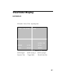
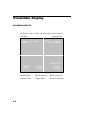
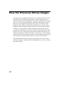
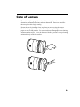
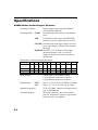
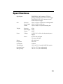
User’s Manual
SR-Series
MOTION ANALYSIS SYSTEMS DIVISION
EASTMAN KODAK COMPANY
Table of Contents
CHAPTER 1 - INTRODUCTION
Introduction ......................................................................................... 1.1
Table of contents ................................................................................. 1.2
Warranty .............................................................................................. 1.3
How to use this manual ........................................................................ 1.4
Precautions .......................................................................................... 1.5
CHAPTER 2 - CONTROLS AND CONNECTORS
Visual introduction .............................................................................. 2.1
Processor.............................................................................................. 2.2
Processor rear panel ............................................................................. 2.3
Processor front panel .......................................................................... 2.5
Camera ................................................................................................. 2.6
Viewfinder display .............................................................................. 2.7
CHAPTER 3 - OPERATING THE MOTION CORDER SR SERIES
Getting started ...................................................................................... 3.1
Preparing to make a recording ............................................................. 3.2
Recording ............................................................................................ 3.8
Viewing a recording ............................................................................ 3.9
Using the system menu ........................................................................ 3.12
CHAPTER 4 - RECORDING STRATEGIES
Introduction ......................................................................................... 4.1
How the Processor stores images ........................................................ 4.2
Start ...................................................................................................... 4.3
Center .................................................................................................. 4.4
End ....................................................................................................... 4.5
Random................................................................................................ 4.6
Choosing a record mode ...................................................................... 4.7
CHAPTER 5 - ROUTINE CARE
Specifications ....................................................................................... 5.1
ADDENDUM
Using software command .................................................................... A.1
Status query codes ............................................................................... A.2
(continued)
Table of Contents
Moving Images to your computer........................................................ A.7
Image download utility ........................................................................ A.8
TIFF file format ................................................................................... A.12
SCSI download application note.......................................................... A.17
Chapter 1 - Introduction
Introduction
Table of Contents
Warranty
How to Use This Manual
Precautions
Introduction
The KODAK Motion Corder Analyzer, SR series is designed to be a valuable
addition to the engineer’s problem solving tool kit. The compactness, ease of
operation, fast framing rates and instant video playback make evaluating your
most difficult motion related problems simple.
The live setup feature allows the user to see the image before recording so that
the time required to solve the problem is minimized. There is no guesswork
about exposure levels or image composition. What the user sees on the video
monitor is what will be captured in memory when the Trigger key is pressed.
The information in this manual will teach you how to operate the KODAK
Motion Corder Analyzer, SR series.
1.1
Warranty
NEW EQUIPMENT WARRANTY
KODAK MOTION CORDER ANALYZER, SR SERIES
Eastman Kodak Company, Motion Analysis Systems Division, warrants this KODAK
Motion Corder Analyzer, Model SR series and accessories manufactured by Eastman
Kodak Company, to function properly for one year from date of shipment, if the warranty registration card was filled out and returned to KODAK San Diego within thirty
days of shipment.
Kodak agrees to perform the following equipment warranty services in the United States.
1. Repair service: If shipped to us, repairs will be made at no charge.
2. Parts replacement: Replacements parts installed under warranty will be provided
at no charge.
THIS WARRANTY DOES NOT APPLY UNDER THE FOLLOWING CONDITIONS:
Failure to operate the KODAK Motion Corder Analyzer, Model SR series in accordance
with Kodak’s written instructions, including environmental specifications listed in the
User’s Manual.
If there is evidence of the KODAK Motion Corder Analyzer, Model SR series being
subjected to accidental damage, misuse or abuse.
If the KODAK Motion Corder Analyzer, Model SR series has been repaired or tampered
with by persons other than Kodak personnel, customer personnel trained by Kodak or
without permission of Kodak.
Shipping damage is not covered by this warranty. The purchaser has the responsibility to
place a claim of damage in shipment with the carrier.
KODAK makes no other warranties, express or implied, including the implied warranties
of merchantability and fitness for a particular purpose. If this KODAK Motion Corder
Analyzer, Model SR series does not function properly during the warranty period,
KODAK will repair it without charge according to the terms stated above. Repair
without charge is KODAK’S only obligation under this warranty. KODAK will not be
responsible for any consequential or incidental damages resulting from the sale use or
improper functioning of this equipment even if loss or damage is caused by the negligence or other fault of KODAK.
Manual Part Number 91000088-002 Rev. A
KODAK is a trademark.
© Copyright Eastman Kodak Company, 1998
1.2
How to Use This Manual
DEFINITION OF TERMS
You will notice as you read this manual that some of the information is presented as a NOTE, CAUTION or WARNING. It is important that you understand the significance of these three terms.
NOTE
A note contains information that we wish to emphasize regarding the operation of
your Motion Corder SR series.
CAUTION
A caution is intended to warn you that a certain operation or condition may cause
harm to your Motion Corder SR series.
WARNING
A warning is important to the safety of everyone operating the Motion Corder SR
series and should not be disregarded under any circumstances.
CHAPTER ONE, INTRODUCTION
Contains the Warranty, precautions, introduction and how to use this manual.
CHAPTER TWO, CONTROLS AND CONNECTORS
An introduction to the components of your Motion Corder SR series. Explains
the use of each connector and control on the Camera and the Processor.
CHAPTER THREE, OPERATING THE MOTION CORDER SR SERIES
Explains how to make and playback a recording.
CHAPTER FOUR, RECORDING STRATEGIES
Provides a model for understanding how a solid state recorder works and also
provides the background information for selecting an appropriate record mode.
CHAPTER FIVE, SPECIFICATIONS
Contains specifications.
If you require additional information not included in this manual regarding the
care, technical service and operation of your Motion Corder SR series please
contact our service department in San Diego by calling:
800 - 854 - 7006
1.3
Precautions
TEMPERATURE
The KODAK Motion Corder Analyzer, SR series, is designed to operate satisfactorily in an environment where the ambient temperature is between -15 and 35
degrees Centigrade (5 and 95 degrees Fahrenheit), and there is no condensation
present.
STORAGE
Do not store the equipment in an area where the temperature will drop below -20
degrees or exceed 70 degrees Centigrade (-4 to 158 degrees Fahrenheit). Ensure
that moisture does not condense on the system.
SHIPPING
When shipping, use the shipping carton in which the unit was originally delivered. If you must frequently ship your Motion Corder SR series, you may wish
to purchase an accessory carrying case that has been designed for this purpose.
Do not ship the equipment in an area where the temperature will drop below -20
degrees or exceed 70 degrees Centigrade (-4 to 158 degrees Fahrenheit). Ensure
that moisture does not condense on the system.
1.4
Precautions
FEDERAL COMMUNICATIONS COMMISSION STATEMENTS
WARNING: This equipment generates, uses and can radiate radio frequency
energy and if not installed and used in accordance with the instruction manual,
may cause interference to radio communications. It has been tested and found to
comply with the limits for a Class “A” computing device pursuant to Subpart B
of Part 15 of the FCC Rules and VDE 0871 Class “B”, which are designed to
provide reasonable protection against such interference when operated in a
commercial environment. Operation of this equipment in a residential area is
likely to cause interference in which case the user at his own expense will be
required to take whatever measures may be required to correct the interference.
This device complies with Part 15 of the FCC Rules and VDE 0871. Operation is
subject to the following two conditions: (1) this device may not cause harmful
interference, and (2) this device must accept any interference received including
interference that may cause undesired operation.
WARNING
This product is grounded through the power cord. This protective ground connection is essential for safe operation of the equipment. Avoid electrical shock
by plugging the power cord into a properly wired receptacle. A loss of the protective ground, for any reason, could result in electrical shock. Use the proper
power cord and insure that it is in good condition.
CAUTION
To avoid the risk of fire, use the fuse specified for the equipment. The proper
fuse is listed on the back panel of the equipment. To avoid the risk of an explosion, do not operate this product in an explosive atmosphere.
1.5
Chapter 2 - Controls and
Connectors
Visual Introduction
Processor
Processor Rear Panel
Processor Front Panel
Camera
Viewfinder Display
Visual Introduction
THE KODAK MOTION CORDER ANALYZER, SR SERIES
The Motion Corder has several components; a Processor, Power Supply, Camera and
optional LCD Viewfinder or optional Viewfinder with Hi 8 VCR. The Camera, a
carrying handle and the viewfinder can be attached to the Processor by sliding their
mounting rails into the slots along the top and sides of the Processor case.
2.1
Processor
REAR PANEL
The rear panel of the Motion Corder Processor has a control panel, a connector
panel and the AC power input connector with fuses.
CONTROL PANEL
The control panel has eight
membrane push buttons that
control setup, recording and
playback.
CONNECTOR PANEL
The connector panel has a
power on indicator, different
types of trigger inputs, sync
inputs, and a video output.
REC
READY
MODE
TRIGGER
EXT IN
TRIGGER IN
Y/C
TRIGGER SW IN
STOP
MENU
ESC
ENTER
POWER
SYNC OUT
VIDEO OUT
RS232C
POWER INPUT
The AC power input is a
standard IEC/CEE plug
connector. The KODAK
Motion Corder can be ordered
with input power of either 110
volts, 60 Hertz AC or 220
volts, 50 Hertz AC. The input
power line is fused at 6.3 Amperes. The power switch on the front panel of the
Processor turns the Motion Corder on and off.
CAUTION
The KODAK Motion Corder Analyzer must be turned off before connecting or
disconnecting the AC power cord.
2.2
Processor Rear Panel Connectors
EXT IN
A BNC type connector that
accepts a synchronizing signal
input from an optional signal
generator, allowing the user to
control the start of each frame.
EXT IN
Y/C
POWER
Y/C
A multipin connector that
carries the luminance and
chroma components of the
output video as separate signals.
Connect to video monitors and
VCRs equipped with the same
style video input connectors for
higher quality video.
TRIGGER IN
TRIGGER SW IN
SYNC OUT
VIDEO OUT
RS232C
POWER
An indicator light that illuminates when power is turned at the front panel of the
Processor.
TRIGGER IN
A BNC type connector that accepts a TTL compatible signal to start or end a
recording depending upon the record mode selected. The input is connected to an
opto-isolator requiring roughly 10 milliamps drive current from a 5 volt source.
TRIGGER SW IN
A switch closure between the shield and the center conductor of this BNC type
connector will start or stop a recording depending upon the record mode selected.
SYNC OUT
A BNC type connector that provides a TTL compatible synchronizing signal at
the beginning of each picture frame.
VIDEO OUT
BNC type connector that carries the video output signal from the Motion Corder.
This output is designed to drive a 75 Ohm coaxial cable that can be connected to
a video monitor, VCR or hard copy video printer.
RS232C
A twenty five pin D subminiature connector for a serial data communication port.
This port is for connection to a remote computer and conforms to the RS232C
specification.
2.3
Processor Rear Panel
CONTROLS
REC
READY
TRIGGER
MODE
STOP
MENU
ESC
ENTER
REC READY
Press this button to place the Motion Corder in a ready to record state. Press the
TRIGGER button next to make a recording, or to return to Live mode press the
REC READY button a second time.
TRIGGER
To start a recording first press the REC READY button and then press the
TRIGGER button.
MODE
The MODE button toggles the Motion Corder between Live and Playback
modes.
This button toggles the playback direction. Press the button once to change from
forward to reverse play, press the button again to return to play forward.
STOP/ESC
This button serves a dual purpose, if you are playing back a recording press this
button to stop playback. If you are changing Motion Corder parameters using the
menu system, press the STOP button to exit from a menu to Live.
These buttons decrease the shutter speed in Live mode, decrease the play frame
rate, or move you down through the menu selections. These buttons also move
the Y reticle down and the X reticle to the left.
MENU/ENTER
Press this button to open a menu. If you are in Live mode, the menu that appears
deals with the various record parameters. If you are playing back a recording, the
menu deals with playback and display parameters. Use the arrow keys on either
side of the menu button to move through the menu and then press the menu
button to select an option.
These buttons increase the shutter speed in Live mode, increase the play frame
rate, or move you up through the menu selections. These buttons also move the
Y reticle up and the X reticle to the right.
2.4
Processor Front Panel
TOP SECTION
The front panel of the Motion
Corder is broken into two sections,
the top panel carries connections
for the camera and the viewfinder.
CAMERA
DC OUT 7.5 V
VIDEO OUT
MCDL
MCDL
A nine pin D subminiature connector that accepts the cable connected
to the Multi Channel Data Link
(MCDL). The User can supply
analog and digital data to be
recorded along with the images
from the Imager.
SCSI
LOOP THROUGH
SCSI
This is the Small Computer System
Interface (SCSI) input connector.
This connector accepts SCSI
protocol commands from a computer and provides a data path for
digital video downloads.
LOOP THROUGH
A SCSI connection to the next
device on the SCSI bus, or if the Motion Corder Processor is the last device on
the SCSI bus, a termination plug should be inserted in this connector.
BOTTOM SECTION
The main power switch, a switch for the lights, a 12 volt AC power connector for
the lights and a power on indicator are located on the lower panel.
CAUTION
The 12 VAC for the lights must have at least a 75 watt but no more than 150 watt
load for proper operation. If you are using a 220 Volt AC source, you must turn
the lights ON and OFF with the light switch next to the main power switch.
If the lights do not come on, make sure that both lights are switched ON at the
lamp head and then turn the power to the lights OFF and then back ON using the
main light switch next to the power switch. The lights will not illuminate if you
turn the lamps OFF and then try to turn them back ON again using the switches at
each lamp head.
2.5
Camera
MOUNTING THE CAMERA
The camera head has four 1/4-20 threaded screw holes for mounting, one on each
side. There are two additional holes per side for a locating pin used by some
tripods. This camera head can also be mounted on the Processor by sliding the
T-Bar on any one of its sides into a matching slot along the sides or the top of
the Processor. In most situations the camera is attached to an adapter plate via
the mounting point on the bottom of the camera head. The adapter plate accepts
the camera head and two small lights.
ATTACHING THE LENS
The camera is equipped with a standard C-mount lens adapter. Insert the lens
into the threads and then rotate the lens clockwise until it stops turning with
gentle pressure. Turn the lens counterclockwise to remove it.
2.6
Viewfinder Display
LIVE DISPLAY
ID Number Date or Time Operating State
<01>
04 -15 -98
LIVE
X:256 Y:120
000000
A: 000
B: 000
1/250
START
250FPS
Reticle X,Y Coordinates
MCDL Digital
MCDL Analog A
MCDL Analog B
Exposure Time
Trigger Mode
Record Frame Rate
2.7
Viewfinder Display
PLAYBACK DISPLAY
ID Number Date or Time Operating State Frame Number
Play Rate
Elapsed Time
<01>
04 -15 -98
FWD30
000000
1/250
MCDL Digital
Exposure Time
2.8
A: 000
START
STOP
00001
0000.0000sec
X:256 Y:120
B: 000
250FPS
Reticle X,Y Coordinates
MCDL Analog A MCDL Analog B
Trigger Mode
Record Frame Rate
Chapter 3 - Operating the
Motion Corder
Getting Started
Preparing to Make a Recording
Viewing a Recording
Using the System Menu
Getting Started
Connect the KODAK Motion Corder Analyzer, SR series components together as
illustrated below:
Plug a power cord into the lower section of the rear panel and then turn on the
power at the front panel. The Motion Corder will come up in Live mode after the
power is turned on and it has performed its self checks successfully.
When the Motion Corder is in Live the Camera video is displayed on the
viewfinder. Notice that the word Live appears in the display on the video monitor to show that the processor is in Live mode. Use Live mode to adjust the lens,
tripod and the lighting for best results. The picture on the monitor is absolutely
accurate as far as composition, focus and exposure are concerned. The images
recorded by your Motion Corder will be as they appear on the viewfinder in Live
mode.
3.1
Preparing to Make a Recording
Before you make a recording you may want to change one or more record
parameters. You can change the exposure time, record mode, frame rate, display
size, ID number and shutter speed plus several other things from the control
panel on the rear of the Processor. The control panel works in conjunction with
the viewfinder to display the choices you need to make.
Use the s and t arrows to change the exposure time when you are in Live mode
and are not in a menu. The current exposure time is shown in the lower left
corner of the viewfinder display.
Press the MENU/ENTER button to display the live menu on the viewfinder. The
menu should appear as follows:
è
- - - REC PARAMETERS - - 1. TRIGGER MODE
START
2. FRAME RATE
250 FPS
3. DISPLAY SIZE
512X480
4. ID NUMBER
01
5. GAMMA CORRECTION 1.0
6. SYSTEM
7. ESC
Use the s and t arrows to move up and down the menu. Each of the items in
the menu have a sub menu, press the MENU/ENTER button again to open a sub
menu for the highlighted item. Once you have used the arrow buttons to highlight your sub menu selection press the MENU/ENTER button a third time to
enter the new parameter.
NOTE
Pressing the STOP/ESC button one or more times, depending on your location
in the menu tree, will return the Motion Corder to Live mode.
3.2
Preparing to Make a Recording
SELECTING A TRIGGER MODE
Open the Live menu and highlight TRIGGER MODE. Press the MENU/ENTER
button to open the TRIGGER MODE sub menu. There are four record modes:
- - - REC PARAMETERS - - 1. TRIGGER MODE
START
è
START
CENTER
END
RANDOM (press MENU/ENTER to select 1, 10, or 50 frames)
ESC
START MODE
Highlight START MODE and press the MENU/ENTER button. To begin
recording first press the REC READY button and then the TRIGGER button.
The processor will record images until every frame in memory has been filled.
The processor will automatically stop the recording when the memory is full.
A trigger signal input through either the TRIGGER IN or the TRIGGER SW IN
connector on the rear panel of the processor has the same effect as pressing the
TRIGGER button. To make a START mode recording using an external trigger
signal, select the START mode as above, press the REC READY button and then
supply a trigger signal input either to TRIGGER IN or to TRIGGER SW IN.
Remember TRIGGER IN requires a positive 10 mA TTL level signal to drive the
opto-isolator or TRIGGER SW IN requires a simple contact closure, with no
voltage present, across its connector.
CENTER MODE
Highlight CENTER MODE and press the MENU/ENTER button. To begin
recording first press the REC READY button and then the TRIGGER button.
The processor will record images until a trigger signal is received, either through
TRIGGER IN, TRIGGER SW IN or by pressing the TRIGGER button again.
The CENTER mode records an equal number of frames before and after the
trigger signal input. A trigger signal causes the processor to mark the frame that
was being recorded at the time the trigger was received as the trigger point. The
processor records a number of frames equal to half the number of frames available in memory after the trigger point and then stops recording.
3.3
Preparing to Make a Recording
SELECTING A RECORD MODE (CONTINUED)
END MODE
Highlight END MODE and press the MENU/ENTER button. To begin recording
first press the REC READY button and then the TRIGGER button. The processor will record images until you press the TRIGGER button again, or a trigger
signal is received through TRIGGER IN or TRIGGER SW IN. The processor
stops recording the instant the trigger signal is received. The video stored in
memory will contain images covering events up to the time when the trigger
signal was received.
RANDOM MODE
Highlight RANDOM MODE and press the MENU/ENTER button to select one
frame recordings, pressing MENU/ENTER again will select ten frame recordings, pressing MENU/ENTER a third time will select fifty frame recordings.
Pressing MENU/ENTER again will cycle you through the same selections again.
To begin recording first press the REC READY button and then the TRIGGER
button. The processor will record 1, 10, or 50 pictures, each time the TRIGGER
button is pressed, or when a trigger signal is received through TRIGGER IN or
TRIGGER SW IN.
SELECTING A FRAME RATE
Open the Live menu and highlight FRAME RATE. Press the MENU/ENTER
button to open the FRAME RATE sub menu. The frame rate options presented
depend on the model Motion Corder that you purchased:
- - - REC PARAMETERS - - 2. FRAME RATE 250FPS
é
è
250FPS
500FPS
1000FPS
2000FPS
3000FPS
ê
Use the s and t arrows to move up and down the list of frame rates. Press the
MENU/ENTER button to select the highlighted frame rate.
3.4
Preparing to Make a Recording
SELECTING A DISPLAY SIZE
Open the Live menu and highlight DISPLAY SIZE. Press the MENU/ENTER
button to open the DISPLAY SIZE sub menu. There are seven display sizes that
permit you to balance display size (resolution) against number of frames recorded.
- - - REC PARAMETERS - - 3. DISPLAY SIZE 512X480
è
512X480
512X240
256X240 <X2>
256X120
128X120 <X4>
128X80
128X34
ESC
Use the s and t arrows to move up and down the list of display sizes. Press the
MENU/ENTER button to select the highlighted display size. If ZOOM is turned
on, the image is electronically expanded to full screen size when <X2> or <X4>
appears next to the display size. ZOOM is listed in the SYSTEM menu.
The display size must decrease in order to reach record rates of 500 or more
frames per second (fps). As the display size decreases the number of frames that
can be recorded increases. The table below details legal combinations of frame
rate and display size.
Di splay
Size
Standard
Memory
Memory
Option 2
Memory
Option 3
Frames
Frames
Frames
512 x 480
546
1,365
2,184
512 x 240
1,092
2,730
4,368
256 x 240
2,184
5,460
8,736
256 x 120
4,368
10,922
17,472
128 x 120
8,736
21,840
34,944
128 x 80
13,104
32,768
52,416
128 x 34
26,208
65,520
104,832
Divide the number of frames available by
the frame rate to determine the amount of
record time available.
3.5
Preparing to Make a Recording
RECORD RATE AND DISPLAY SIZES
30fps
60fps
125fps
250fps
500fp s
1000 fps
2000fps
3000fps
5000fps
512 x 480
ü
ü
ü
ü
512 x 240
ü
ü
ü
ü
ü
256 x 240
ü
ü
ü
ü
ü
ü
256 x 120
ü
ü
ü
ü
ü
ü
ü
128 x 120
ü
ü
ü
ü
ü
ü
ü
ü
128 x 80
ü
ü
ü
ü
ü
ü
ü
ü
ü
128 x 34
ü
ü
ü
ü
ü
ü
ü
ü
ü
10000fp s
ü
SR 500 Frame Rates
SR 1000 Frame Rates
SR Ultra Frame Rates
As you can see from the table above it is possible to select different display sizes
for a specific frame rate. Selecting a smaller display size will increase the
number of frames that you can record.
SELECTING AN ID NUMBER
Open the Live menu and highlight ID NUMBER. Press the MENU/ENTER
button to open the ID NUMBER sub menu. There are three options:
- - - REC PARAMETERS - - 3. ID NUMBER <99>
è
CLEAR
INCREMENT
DECREMENT
ESC
Use the s and t arrows to move up and down the options. Press the MENU/
ENTER button to select the highlighted option. CLEAR sets the ID Number to
<01>. INCREMENT increases the ID Number by one and DECREMENT
decreases the ID Number by one. The ID Number automatically increments by
one after each recording.
3.6
Preparing to Make a Recording
GAMMA CORRECTION
Open the Live menu and highlight GAMMA CORRECTION. Press the MENU/
ENTER button to open the GAMMA CORRECTION sub menu. A gamma value
of 1.0 applies no black stretch to the video and a value of 0.4 applies maximum
black stretch to the video.
- - - REC PARAMETERS - - 5. GAMMA CORRECTION 0.6
1.0
0.9
0.8
0.7
è
0.6
0.5
0.4
ESC
Use the s and t arrows to move up and down the options. Press the MENU/
ENTER button to select the highlighted option.
RETURNING TO LIVE MODE
Once you have finished making any changes using the Live Menu highlight ESC
and press the MENU/ENTER button to move up one level in the menu structure.
Pressing the STOP/ESC button will also return you to the Live mode, except in
the SYSTEM menu.
You should be able to see a picture of your subject on the viewfinder at this
point. Adjust the lens focus, lens aperture, tripod and lighting to compose the
scene you wish to record. You may also change the shutter speed to achieve a
properly exposed image on the viewfinder.
3.7
Preparing to Make a Recording
SELECTING A SHUTTER SPEED
When you are in the Live mode, use the s and t arrows to increase and decrease the shutter speed. The shutter speeds for each frame rate are shown
below:
F ram e
Rate
30 fps
Shutter Speed
1/30
1/60
ü
ü
ü
ü
ü
ü
ü
ü
ü
ü
ü
ü
ü
ü
ü
ü
ü
ü
ü
ü
ü
ü
ü
ü
ü
ü
ü
ü
ü
ü
ü
ü
ü
ü
ü
ü
ü
ü
ü
ü
ü
ü
ü
ü
ü
ü
ü
ü
ü
ü
ü
ü
ü
ü
ü
60 fps
125 fps
250 fps
500 fps
1000 fps
2000 fps
3000 fps
5000 fps
10000 fps
1/125
1/250
1/500
1 / 1 ,0 0 0
1 / 2 ,0 0 0
1 / 3 ,0 0 0
1 / 5 ,0 0 0
1 / 1 0 ,0 0 0 1 / 2 0 ,0 0 0
RECORDING
If you are satisfied with the composition, focus, and exposure of your subject
press the REC READY button and then the TRIGGER button to start a recording.
A recording may also be started, after a REC READY, by a trigger signal at the
TRIGGER IN connector or a contact closure at the TRIGGER SW IN connector.
A second trigger signal is needed to end the recording in all but Start mode
recordings.
3.8
Viewing a Recording
DISPLAY MODE
All playback functions
are done in the Display
mode. Press the
MODE button to toggle
between Display and
Live mode.
Press the (Direction)
button to playback the
recording in memory
starting with the frame
currently displayed on
the viewfinder. Press
the (Direction)
button again to change
direction of playback
from forward to reverse
or from reverse to
forward. Use the s and
t arrows to increase or
decrease the play rate.
ID Number Date or Time Operating State Frame Number
Play Rate
Elapsed Time
<01>
04 -15 -98
FWD30
000000
1/250
MCDL Digital
Exposure Time
A: 000
START
STOP
00001
0000.0000sec
X:256 Y:120
B: 000
250FPS
Reticle X,Y Coordinates
MCDL Analog A MCDL Analog B
Trigger Mode
Record Frame Rate
Press the STOP/ESC button once to pause the playback. The word STEP will
appear next to the Frame Number in the data display. You can step forward or
backward one frame at a time by using the s and t arrows.
Press the STOP/ESC button again to go from step to stop. The word STOP will
appear next to the Frame Number in the data display. You can jump to the start
of the recording by pressing STOP/ESC a third time. Pressing STOP/ESC
repeatedly will jump the display between the first frame of the recording and the
frame where you first pressed STOP/ESC.
NOTE
The following note applies to CENTER, END, and RANDOM trigger modes.
If you did not fill the video memory with your last recording, images from a
previous recording can still be seen in playback, or if it is your first recording
since power up the unrecorded frames will display noise. When you make a
recording that does not fill memory, use the Block Display feature to playback
the current recording.
3.9
Viewing a Recording
Press the MODE button to enter the Display mode. Press the MENU/ENTER
button to bring up the Display menu on the viewfinder. The menu should appear
as follows:
- DISPLAY PARAMETERS è
1. BLOCK DISPLAY
2. BLOCK START POINT
3. BLOCK END POINT
4. RETICLE
5. SYSTEM
6. ESC
OFF
OFF
Use the s and t arrows to move up and down the menu. Some of the items in
the menu have a sub menu, press the MENU/ENTER button again to open a sub
menu for the highlighted item. Once you have used the arrow buttons to highlight your sub menu selection press the MENU/ENTER button again to enter the
new parameter.
NOTE
Press the STOP/ESC button at any time within any menu to exit the menu tree
and return to Display mode.
DISPLAYING A BLOCK OF FRAMES
To review a small portion of your recording, frames 100 through 120 for example, follow this procedure.
l
Use the control panel to stop the playback at frame 100.
Press the Menu button, select BLOCK START POINT, and then press
the MENU/ENTER button again to select the current frame as the start
point.
Press STOP/ESC to return to playback.
Use the Control Panel to move on and stop the playback at frame 120.
Press the Menu button, select BLOCK END POINT, and then press the
MENU/ENTER button again to select the current frame as the end point.
Select BLOCK DISPLAY and press the MENU/ENTER button to open
the sub menu.
Select ON and press the MENU/ENTER button to turn on the Block
Display mode.
Press STOP/ESC to return to playback.
l
Press the
l
l
l
l
l
l
l
3.10
(Direction) button to playback frames 100 through 120
Viewing a Recording
USING THE RETICLE
Open the Playback menu and highlight RETICLE. Press the MENU/ENTER
button to open the RETICLE sub menu. There are three options:
- DISPLAY PARAMETERS 4. RETICLE
è
ON
OFF
ESC
ON
Use the s and t arrows to move up and down the options. Press the MENU/
ENTER button to select the highlighted option. When the reticle is on, the reticle
X and Y coordinates appear in the lower right quadrant of the picture and a
reticle overlays the picture.
When you return to the display after turning the reticle ON you will be able to
adjust the X reticle position. Press MENU/ENTER to step to the Y reticle
position adjust. Press the MENU/ENTER button once more to enter the single
step mode.
If you are in play and the reticle is already on, press STOP/ESC to enter single
step mode. Find the frame you want to measure and then press MENU/ENTER
button, the word STEP in the data display will change to < X >, then use the s
and t arrows to change the reticle X coordinate. Press the MENU/ENTER
button again and then use the s and t arrows to change the reticle Y coordinate.
Press the MENU/ENTER button once more to return to the single step mode.
Once you have entered the single step mode the MENU/ENTER button will cycle
through X coordinate adjust, Y coordinate adjust, and single step. You can exit
the cycle at any point by pressing the STOP/ESC button or the (Direction)
button to resume playback.
3.11
Using the System Menu
The system menu appears on both the live menu and the playback menu. Highlight system on either menu. Press the MENU/ENTER button to open the system
sub menu that appears as follows:
- SYSTEM PARAMETERS è
1. EDGE ENHANCEMENT
2. ZOOM
3. DISPLAY
4. DATE/TIME SET
5. EXTERNAL I/O
6. COLOR TEMP.
7. OTHERS
8. STATUS
9. ESC
OFF
OFF
ALL<DATE>
USER1 [color models only]
Use the s and t arrows to move up and down the menu. Some of the items in
the menu have a sub menu, press the MENU/ENTER button again to open a sub
menu for the highlighted item. Once you have used the arrow buttons to highlight your sub menu selection press the MENU/ENTER button again to enter the
new parameter.
SELECTING THE AMOUNT OF EDGE ENHANCEMENT
Open the System menu and highlight EDGE ENHANCEMENT. Press the
MENU/ENTER button to open the EDGE ENHANCEMENT sub menu that
appears as follows:
- SYSTEM PARAMETERS 1. EDGE ENHANCEMENT OFF
è
OFF
ON1
ON2
ON3
ESC
Use the s and t arrows to move up and down the options. Press the MENU/
ENTER button to select the highlighted option. There are three levels of enhancement with ON1 be the least enhancement and ON3 being the most. Edge enhancement will make your images appear sharper.
3.12
Using the System Menu
USING ELECTRONIC ZOOM
Open the System menu and highlight ZOOM. Press the MENU/ENTER button
to open the ZOOM sub menu that appears as follows:
- SYSTEM PARAMETERS 2. ZOOM
è
OFF
ON
ESC
OFF
Use the s and t arrows to move up and down the options. Press the MENU/
ENTER button to select the highlighted option. The ZOOM feature is only active
when the display size is set to 256X240 or 128X120. When ZOOM is turned on
the Display Size sub menu indicates the magnification with a <X2> or <X4>
next to the display size.
CHANGING THE DATA BORDER DISPLAY
Open the System menu and highlight DISPLAY. Press the MENU/ENTER
button to open the DISPLAY sub menu that appears as follows:
- SYSTEM PARAMETERS 3. DISPLAY
ALL<DATE>
è
DATE/TIME
DATE
DISPLAY
ON1
ESC
Use the s and t arrows to move up and down the options. Press the MENU/
ENTER button to toggle the highlighted option. The DATE/TIME function
toggles between DATE and TIME with each press of the MENU/ENTER button.
The DISPLAY function toggles through three options, ON1, ON2, and OFF.
ON1 turns on the complete data border. ON2 turns on just the information at the
top of the screen. OFF turns the entire data border off.
3.13
Using the System Menu
SETTING THE TIME AND DATE
Open the System menu and highlight DATE/TIME SET. Press the MENU/
ENTER button to open the DATE/TIME SET menu that appears as follows:
- SYSTEM PARAMETERS 4. DATE/TIME
è
SET
ESC
SET
Use the s and t arrows to move up and down the options. Press the MENU/
ENTER button to toggle the highlighted option. SET puts the Date and Time
below the menu that appears as follows: 04.03.1998 10:46:29
Use the Menu button to select a character and the s and t arrows to change the
value. Set the time a minute of two ahead so that you can start the Motion Corder
clock at the correct time. Once you have changed the seconds value the Menu
button returns you to the sub menu shown below.
è
SET
START&ESC
Highlight START&ESC and press the Menu button when the time you entered
matches the correct time.
CONFIGURING THE EXTERNAL I/O PORTS
Open the Sytem menu and highlight EXTERNAL I/O. Press the MENU/ENTER
button to open the EXTERNAL I/O menu that appears as follows:
- SYSTEM PARAMETERS 5. EXTERNAL I/O
RS232C
4800bps
EXTERNAL SYNC
OFF
MCDL DISPLAY
OFF
SCSI ID
<5>
è
ESC
Use the s and t arrows to move up and down the options. Press the MENU/
ENTER button to toggle the highlighted option.
3.14
Using the System Menu
RS232C
You need to know the configuration of the RS232C port located on the rear panel
before you can expect to communicate with the processor using your personal
computer. You must set the COM port you are using to communicate with the
Motion Corder to 8 data bits, 2 stop bits, and no parity. You cannot change these
parameters on the Motion Corder. The only RS232 parameter that you can
change on the Motion Corder is the baud rate. Use the s and t arrows to move
to the RS232C option on the EXTERNAL I/O menu. Press the MENU/ENTER
button to toggle between a baud rate of 2400bps and 4800bps.
EXTERNAL SYNC
Use the s and t arrows to move to the EXTERNAL SYNC option on the
EXTERNAL I/O menu. Press the MENU/ENTER button to toggle EXTERNAL
SYNC on or off. EXTERNAL SYNC is a waveform that starts each frame of a
recording. A transition from 0 volts to 5 volts is required to start each frame
when EXTERNAL SYNC is on.
MCDL DISPLAY
Use the s and t arrows to move to the MCDL DISPLAY option on the EXTERNAL I/O menu. Press the MENU/ENTER button to toggle MCDL DISPLAY on or off. The MCDL is used record digital and analog data from an
experiment along with images taken at the same time as the data.
SCSI ID
Use the s and t arrows to move to the SCSI ID option on the EXTERNAL I/O
menu. Press the MENU/ENTER button to toggle through the SCSI ID values (1-7).
The SCSI connectors are on the front panel; of the Processor. If the Processor is
the last device on the SCSI bus a SCSI termination block must be plugged into
the open LOOP THROUGH connector. A default SCSI address of 5 is recommended as this address will normally be available.
NOTE
If you change the SCSI ID you must cycle power to the Motion Corder for the
change to take effect.
3.15
Using the System Menu
ADJUSTING COLOR TEMPERATURE [color models only]
Open the Sytem menu and highlight COLOR TEMP. Press the MENU/ENTER
button to open the COLOR TEMP. menu that appears as follows:
- SYSTEM PARAMETERS 6. COLOR TEMP.
è
USER1
USER1
USER2
USER3
EDIT USER1
EDIT USER2
EDIT USER3
ESC
Use the s and t arrows to move up and down the options. Press the MENU/
ENTER button to select the highlighted option.
The Motion Corder is sensitive to the light source illuminating a scene. Daylight
is blue relative to light from an incadescent light bulb. The COLOR TEMP.
menu options permit you to adjust the Motion Corder for these differences.
Select the
icon for average daylight illumination. Select the
icon
for incandescent lighting. The three USER selections are programable with the
EDIT USER options. Select EDIT USER1 and then press the MENU/ENTER
button to open the EDIT USER1 submenu that appears as follows:
- SYSTEM PARAMETERS EDIT USER1
16 16 16
è
RED UP
RED DOWN
GREEN UP
GREEN DOWN
BLUE UP
BLUE DOWN
CLEAR
ESC
3.16
Using the System Menu
ADJUSTING COLOR TEMPERATURE (CONTINUED)
The three numbers to the right of EDIT USER1 represent the video amplitude of
red, green, and blue. To change the red value highlight RED UP, or RED DOWN on
the menu, and then press the MENU/ENTER button to change its value one count.
Each press of the MENU/ENTER button changes the red amplitude one count.
The color channel values range from zero to sixty three. Leave green set to
sixteen and adjust the red and blue channels to color balance the Motion Corder.
The Motion Color is color balanced when gray objects appear gray, without any
color tinting, on a color video monitor.
To change the overall sensitivity of the Motion Corder change the green channel
value. Increasing green from 16 to 32 will make the Camera one f-stop more
sensitive. When you increase the red and blue values to color balance the Motion
Corder you will have greater sensitivity, but at the cost of increased noise in the
picture.
Return all three channels to the default value of sixteen with CLEAR.
ENABLING OVERHEAT PROTECTION
Open the Sytem menu and highlight OTHERS. Press the MENU/ENTER button
to open the OTHERS menu that appears as follows:
- SYSTEM PARAMETERS 7. OTHERS
è
OVEHEAT
PREVENT
SETUP LEVEL
7.5
- -RESERVED- - -RESERVED- - -RESERVED- ESC
[color models only]
Use the s and t arrows to move up and down the options. Press the MENU/
ENTER button to select the highlighted option. It is possible for the Imager to
overheat when it is operated at 3,000, 5,000, and 10,000 frames per second. A
count down timer appears in the viewfinder imager when overheat prevent is in
effect. The count represents the number of seconds remaining before the Imager
is switched to 250 fps. The counter decrements once each second. When the
count reaches 0000 the frame rate is set to 250 fps.
CAUTION
You can turn overheat prevent off but this may result in damage to the Imager.
3.17
Using the System Menu
CHANGING THE SETUP LEVEL [color models only]
Use the s and t arrows to select SETUP LEVEL. Press the MENU/ENTER
button to toggle between a setup level of 7.5 and 0.0. A setup level of 7.5 is
required for NTSC color signals and a setup level of 0.0 is used for PAL color
signals.
CHECKING SYSTEM STATUS
Open the Sytem menu and highlight STATUS. Press the MENU/ENTER button
to open the STATUS screen that appears as follows:
KODAK
Motion Corder Analyzer
Model SR-Ultra-C
SCSI ........... Enable
MCDL .......... Enable
Video ............ NTSC
Memory ......... None
System Rev ...... 1.12
04-14-1998 14:14:59
The screen gives you the pertinent information about your system. A “C” in the
last character of the model designation indicates a color Motion Corder.
3.18
Chapter 4 - Recording Strategies
Introduction
How the Processor Stores Images
Trigger Modes
Choosing a Record Mode
Introduction
The first section of this chapter describes how the KODAK Motion Corder
Analyzer, SR series moves images in and out of memory. This is intended to
help you decide which record mode is best suited for a particular application.
The Processor stores its images in random access memory (RAM) rather than on
film or magnetic tape. The major advantage of storing pictures in RAM is
speed. There are no moving mechanical parts involved in the recording process.
A mechanical part takes time to stabilize at a particular speed. A mechanical tape
or film transport is the major source of delay between pressing the record key and
when recording begins. How then, does the Processor manage the picture storage
process?
4.1
How the Processor Stores Images
An analogy for the recording and playback process would be a Kodak Carousel
slide projector and a Kodak Carousel slide tray. Think of the Processor as a
Carousel slide projector and the Random Access Memory (RAM) as the Carousel
slide tray. For our discussion the RAM is divided into small sections or frames
that are just large enough to hold a single video image. These frames can be
thought of as the pockets in a slide tray that hold the slides or images. In this
analogy the slide tray holds 546 slides or the processor memory has 546 frames.
A slide tray is usually loaded with slides starting at location number one and
continuing on around the tray in sequence until the last location is loaded. When
the slide tray is full, a slide must be removed before another slide can be put in.
The processor memory is loaded with images in a similar way. The first image is
placed in the first frame of processor memory. The second image is placed in the
next frame and so on until image number 546 is placed in the last location.
The TRIGGER MODE sub menu specifies the procedure used to store frames
into memory during a recording. The four Trigger Modes are: START, CENTER,
END and RANDOM.
4.2
Trigger Modes
START
The START mode fills memory only once and then stops recording. Use the
START mode when you wish to start a recording session manually. This mode is
used when the experiment has an observable start and you are interested in the
action immediately after the recording is started.
4.3
Trigger Modes
CENTER
Use CENTER record mode when you want to see an equal number of pictures
(frames) before and after the event you are trying to study.
The CENTER record mode causes the Processor to use memory as a circular
buffer. Pictures are stored in sequence with the current picture replacing the
oldest picture so that you always have the 546 most recent pictures in memory.
After a trigger occurs the Processor records an additional 107 frames, or half of
the total number of frames available, and then stops recording. The beginning
frame in the recording has the most negative frame number and the last frame has
the most positive frame number; the first frame after the trigger occurred is
marked as frame one.
A trigger may be input through the TRIGGER IN or TRIGGER SW IN connectors on the rear panel of the Processor or by you pressing the TRIGGER switch.
4.4
Trigger Modes
END
The Processor treats memory as a circular buffer when using the END mode.
Pictures are stored in sequence with the current picture replacing the oldest
picture in memory until you press the TRIGGER button again or a trigger signal
is received through TRIGGER IN or TRIGGER SW IN on the rear panel of the
Processor. This approach to recording gives you an infinite amount of record
time while you wait for something to happen. After the recording is stopped you
will have the last 546 frames of action stored in memory.
The END mode is used when the experiment has an observable end and you are
interested in the action immediately before the recording was stopped.
4.5
Trigger Modes
RANDOM
The RANDOM mode records one, ten or fifty frames for each trigger signal
received by the Processor. The Processor continues to record until the memory
has been filled.
4.6
Choosing a Record Mode
Is the event controlled
NO
or predictable?
YES
Is there an external
trigger that relates to
the event?
NO
Find a way to create
a trigger signal using
light, sound or motion.
YES
Does the event have
images before it that NO
need to be captured?
Consider using the
START mode.
YES
Does the event have
NO
images after it that
need to be captured?
Consider using the
END mode.
YES
Choose the CENTER
mode.
Does the event
have an observable
start?
YES
Choose the
START mode
NO
Does the event have
an observable end?
YES
Choose the END
mode
4.7
Chapter 5. Specifications
Care of Lenses
Specifications
Care of Lenses
The surface of photographic lenses have thin coatings that reduce chromatic
aberration, unwanted reflections, and other distortions. Extra care should be
taken to protect this fragile coating.
Protect the lens by installing a lens cap when you are not using the camera.
Brush the lens gently with a camel hair brush or loosely folded piece of lens
paper to remove dust particles. For stubborn dirt use photographic lens cleaning
solution and lens wipes. Never rub the lens with direct pressure or drop cleaning
solution directly on the lens surface.
5.1
Specifications
KODAK Motion Corder Analyzer, SR series
Recording Technique:
Digital images stored in Dynamic Random
Access Memory (DRAM).
Recording Modes: START
Records images until memory is full and then
stops.
END
Continually records images until TRIGGER
button is pressed or trigger signal is received.
CENTER Records images until trigger signal is received.
Saves equal number of frames before and after
the trigger.
RANDOM Records 1, 10 or 50 frames at each trigger
input until memory is full. User can set
number of frames to record on rear panel of
the Processor.
Record Rates at Maximum Output Resolution:
Frames/Sec
30
60
125
250
500
1,000
2,000
3,000
5,000
10,000
Resolution: H
in Pixe ls: V
512
480
512
480
512
480
512
480
512
240
256
240
256
120
128
120
128
80
128
34
SR-Ultra
4
4
4
4
4
4
4
4
4
4
SR-1000
4
4
4
4
4
4
SR-500
4
4
4
4
4
Frame Storage:
Playback Rates:
5.2
546 full frames with standard memory.
1,365 full frames with memory option 2.
2,184 full frames with memory option 3.
NTSC
Step, 1, 2, 5, 10, 15, 30, 60, 120, 240fps, or 1200fps.
PAL
Step, 1, 2, 5, 10, 25, 50, 100, 200, or 250fps.
Synchronizing output:
SYNC OUT BNC connector can output vertical
sync or RECORD gate.
Viewfinder Display:
ID number, date/time, status, frame number,
play rate, elapsed time, exposure, trigger mode,
frame rate, and x,y coordinates
Specifications
Signal Inputs:
TRIGGER IN: BNC connector TTL level
optically isolated input, 10 ma from 5 volts to trigger.
TRIGGER SW IN: BNC connector accepts
contact closure to trigger.
Size:
Processor
Power Supply
Camera
160(w) x 330(d) x 180(h) mm excluding handle
168(w) x 330(d) x 63(h) mm
51(w) x 114(d) x 51(h) mm excluding lens
Weight:
Processor
8.2 kg
Power Supply 2.6 kg
Camera
0.8 kg
Power:
Voltage:
12 VDC (110 or 240 volt with optional power
supply).
Power:
60 watts with out lights
210 watts with lights
Sensor:
658 x 496 pixels.
Gray Scale:
256 levels.
Lens Mount:
C-Mount.
Tripod Mount:
1/4-20 and 3/8-16 standard ANSI hole pattern.
Operating Temp:
-10°C to +35°C (no condensation)
Storage Temp:
-20°C to +70°C (no condensation)
5.3
Using Software Commands
INTRODUCTION
The KODAK Motion Corder Analyzer SR series all have an RS232C connection
on the rear panel of the Processor. If you connect one of your personal computer
COM ports to the RS232 connector you can control the Motion Corder from your
computer keyboard using the terminal program that comes with all versions of
Microsoft Windows.
There are eight commands, each command corresponding to a button on the
Processor’s control panel. After you have setup and are running a terminal
program pressing the “r” on your computer’s keyboard will have the same affect
as pressing the MENU/ENTER button on the Processor’s control panel. The
parameters to use when configuring your terminal program follow.
RS232C SERIAL COMMUNICATIONS PROTOCOL
The Motion Corder is configured for eight data bits, two stop bits, and no parity.
The baud rate default is 4800 bps. Set flow control to none. The Motion Corder
responds to eight bit binary commands shown in this manual as two hexadecimal
characters.
The TX lines of your computer must be wired to the RX lines of the Motion
Corder and the TX lines of the Motion Corder must connect to the RX lines of
your computer. Check the documentation that came with your computer or I/O
card for the correct TX and RX pin numbers. A null modem cable connected
between a COM port on your personal computer and the Motion Corder will
accomplish this in most instances. The Motion Corder RS232C port uses a
25 pin D-subminiature connector with standard RS232C pinouts.
CONTROL CODES
The codes below are in hexadecimal and can be sent to the Motion Corder from a
program that you write. If you use a terminal program, the computer keyboard
letters indicated in the “Key” column will transmit the code to the Motion Corder.
Description
Code Key
65h
e
PLAY switch
68h
h
STOP/ESC switch
69h
i
DOWN switch
6Ah
j
UP switch
71h
q
MODE switch
72h
r
MENU/ENTER switch
73h
s
REC READY switch
74h
t
TRIGGER switch
A.1
Status Query Codes
When you are using the command set from within a software application you have
written, you will need to know the status of each parameter of the Motion Corder.
The status query codes with their responses listed below are for this purpose.
A.2
Code
Query Description
Response & Meaning
81h
ROM Version increases
from 01h
82h
Number of additional
memory boards
00h:
01h:
02h:
none
1 board added
2 boards added
83h
Operation mode
00h:
FFh:
DISPLAY mode
LIVE mode
84h
REC READY
00h:
FFh:
LIVE mode
REC READY mode
85h
SET UP mode
00h:
FFh:
LIVE mode.
SETUP mode
86h
DISPLAY status
00h:
01h:
02h:
03h:
04h:
STOP mode
PLAY mode
REV mode
STEP mode
First frame
87h
TRIGGER MODE status
00h:
01h:
02h:
03h:
START mode
CENTER mode
END mode
RANDOM [ROC] mode
88h
RANDOM [ROC] MODE,
Number of frames
00h:
01h:
02h:
1 frame
10 frames
50 frames
Status Query Codes
Code
Query Description
Response & Meaning
89h
REC RATE
00h:
01h:
02h:
03h:
04h:
05h:
06h:
07h:
08h:
09h:
30 fps
60 fps
125 fps
250 fps
500 fps
1000 fps
2000 fps
3000 fps
5000 fps
10000 fps
8Ah
DISPLAY SIZE
00h:
01h:
02h:
03h:
04h:
05h:
06h:
128 x 40
128 x 80
128 x 120
256 x 120
256 x 240
512 x 240
512 x 480
8Bh
ID NUMBER
**h:
ID number in hexadecimal
8Ch
reserved
8Dh
reserved
8Eh
CABLE SELECT
00h:
Cable 1 (20ft)
8Fh
EXTERNAL SYNC
00h:
01h:
OFF
ON
90h
MCDL DISPLAY
00h:
01h:
OFF
ON
91h
BLOCK DISPLAY mode
00h:
FFh:
OFF
ON
92h
BLOCK START POINT
**h:
upper 2 bytes in hex
93h
BLOCK START POINT
**h:
lower 2 bytes in hex
94h
BLOCK END POINT
**h:
upper 2 bytes in hex
95h
BLOCK END POINT
**h:
lower 2 bytes in hex
A.3
Status Query Codes
A.4
Code
Query Description
Response & Meaning
96h
DATE/TIME DISP
00h:
01h:
DATE DISP
TIME DISP
97h
DISPLAY ON/OFF
00h:
01h:
02h:
ON1
ON2
OFF
98h
YEAR (1000YRS)
**h-.
No. of YRS in hex
99h
YEAR (100YRS)
**h:
No. of YRS, in hex
9Ah
YEAR (10YRS)
**h:
No. of YRS in hex
9Bh
YEAR
**h:
No. of YRS in hex
9Ch
MONTH (10 MOS)
**h:
No. of MOS in hex
9Dh
MONTH
**h:
No. of MOS, in hex
9Eh
DAY (10 DAYS)
**h:
No. of DAYS in hex
9Fh
DAY
**h:
No. of DAYS in hex
A0h
HOURS (10 HOURS)
**h:
No. of HOURS in hex
A1h
HOURS
**h:
No. of HOURS in hex
A2h
MINUTES (10 MINUTES)
**h:
No. of MINUTES in hex
A3h
MINUTES
**h:
No. of MINUTES in hex
A4h
SECONDS (10 SECONDS)
**h:
No. of SECONDS in hex
A5h
SECONDS
**h:
SECONDS in hex
Status Query Codes
Code
Query Description
Response & Meaning
A6h
SHUTTER SPEED
00h:
01h:
02h:
03h:
04h:
05h:
06h:
SPEED I
SPEED 2
SPEED 3
SPEED 4
SPEED 5
SPEED 6
SPEED 7
A7h
DISPLAY RATE
00h:
01h:
02h:
03h:
04h:
05h:
06h:
07h:
08h:
1 fps
2 fps
5 fps
10 fps
15 fps
30 fps
60 fps
125 fps
250 fps
A8h
FRAME COUNT
(10,000 FRAMES)
**h:
FRAME COUNT in hex
A9h
FRAME COUNT
(1000 FRAMES)
**h:
FRAME COUNT in hex
AAh
FRAME COUNT
(100 FRAMES)
**h:
FRAME COUNT in hex
ABh
FRAME COUNT
(10 FRAMES)
**h:
FRAME COUNT in hex
ACh
FRAME COUNT
**h:
FRAME COUNT in hex
ADh
FRAME COUNT
POLARITY
00h:
FFh:
POSITIVE (+)
NEGATIVE (-)
A.5
Status Query Codes
A.6
Code
Query Description
Response & Meaning
AEh
REAL TIME (1000)
**h:
NUMBER in hex
AFh
REAL TIME (100)
**h:
NUMBER in hex
B0h
REAL TIME (10)
**h:
NUMBER in hex
B1h
REAL TIME
**h:
NUMBER in hex
B2h
REAL TIME (0.1)
**h:
NUMBER in hex
B3h
REAL TIME (0.01)
**h:
NUMBER in hex
B4h
REAL TIME (0.001)
**h:
NUMBER in hex
B5h
REAL TIME (0.0001)
**h:
NUMBER in hex
B6h
EDGE ENHANCEMENT
00h:
01h:
02h:
OFF
ON1
ON2
B7h
ZOOM
00h:
01h:
OFF
ON
B8h
RETICLE
00h:
01h:
OFF
ON
B9h
GAMMA
00h:
01h:
02h:
03h:
04h:
05h:
06h:
0.4
0.5
0.6
0.7
0.8
0.9
1.0
B9h
DISPLAY
00h:
01h:
02h:
OFF
ON1
ON2
Moving Images to Your Computer
INTRODUCTION
The Motion Corder has two connectors on its front. One labeled SCSI, and the
other Loop Through. These two connectors make up the SCSI interface that
connects to a SCSI adapter card installed in a personal computer. It is possible to
move images from the Motion Corder’s memory across the SCSI interface for
storage on the hard drive in you computer. You will need to install and setup a
SCSI adapter card in your computer and set the Motion Corder’s SCSI address.
INSTALL A SCSI ADAPTER IN YOUR COMPUTER
After you have purchased a SCSI adapter card, install it in your personal computer following the manufacturer’s instructions. You must also install the SCSI
drivers for the adapter as detailed in the adapter’s instruction manual.
The Motion Corder’s SCSI port must be set to an unused address. Open the
System menu and highlight EXTERNAL I/O. Press the MENU/ENTER button
to open the EXTERNAL I/O menu that appears as follows:
- SYSTEM PARAMETERS 5. EXTERNAL I/O
RS232C
4800bps
EXTERNAL SYNC
OFF
MCDL DISPLAY
OFF
SCSI ID
<5>
è
ESC
Use the s and t arrows to move to the SCSI ID option. Press the MENU/
ENTER button to step through the SCSI addresses (1-7). If the Processor is the
last device on the SCSI connection to your computer a SCSI termination block
must be plugged into the Loop Through connector. A default SCSI address of 5
is recommended as this address will normally be available.
You received a 3.5” floppy disk with your Motion Corder with an application that
will move image frames from a Motion Corder’s memory to your computer’s
hard disk. Use file manager or explorer to list the files on the floppy disk.
Double clicking on setup.exe will automatically install the application on your
computer. Double click the Readcam icon to start the application. An explanation of how to use Readcam is on the following pages.
A.7
Image Download Utility
INTERFACE WINDOW
The following window is displayed when Readcam program is started.
Menu:
Commands are selected here.
Menu
Toolbar
Display window
Statusbar
Tool bar:
Display window:
Status bar:
A.8
Icon shortcuts appear here.
Displays the results.
Explanation of commands is given here.
Image Download Utility
FILE MENU
READ CAMERA
Downloads the picture data from the camera, and saves the data to a file folder on
your personal computer. If a folder has not been selected, the Set Folder dialog
box opens so that you can enter an output folder name. The Set Folder dialog box is
discussed on the next page. Select Read Camera from the File Menu, or click the
icon, and the following dialog box appears.
Camera:
The current imager is shown by SCSI ID number. Click the
down arrow to the right of the Camera text box to reveal a
list of available cameras. Click on the camera you wish to
select.
Session Number:
Corresponds to the Motion Corder’s current Session ID number.
Start Frame #:
Assigns the starting frame number. Frame one marks when
the trigger was received. Frames recorded before the trigger
have negative frame numbers, and those after the trigger have
positive frame numbers. Note there is no frame “0”: the
frame immediately before “1” is “-1”.
Stop Frame #:
Assigns the ending frame number.
Click OK to record all the frames between the Start and Stop frames.
EXIT
Ends and exits this Utility Program.
A.9
Image Download Utility
SETUP MENU
SET FOLDER
Sets the folder and the format to record the picture data. When this command is
selected, the following dialog box shows:
Output folder
Reference button
Output format setting
Output Folder: Selects the folder in which to save the picture data. Click the
Browse button to select an existing folders. The picture data is
saved in a subfolder within the output folder, with its name
containing the session number of the data being downloaded.
File Type:
Select TIFF (Tagged Image Format File) or BMP (Windows
Bitmap File). The picture data is not compressed in either case.
VIEW MENU
SET FONT
Sets the font to be used in the display window.
TOOLBAR
Switches Show/Hide for Tool bar.
STATUS BAR
Switches Show/Hide for Status bar.
A.10
Image Download Utility
DESTINATION FOLDERS
The picture data is saved in a separate subfolder for each session within
C:\DATA, the selected as the destination folder.
The name for each session folder is generated using the following format.
Sxxxyz.n
S
Session folder names always begin with an “S”.
xxx
Where xxx is the session number as 3 decimal digits.
y
A “T” indicates Tiff format and a “W” Bmp format images.
z
A “C” indicates color images and an “M” indicates monochrome.
n
Where n is incremented by one for each download from the
same session.
For example, the picture data of “Tiff format, color mode, and session number 1”
will be recorded in a sub-folder named “S001TC.1”.
FILE NAMES FOR RECORDED PICTURE DATA
File names are generated using the following format:
Fsdddddd.eee
F
File names always begin with an “F”.
s
A minus sign ( - ) is inserted for pretrigger images (negative
frame numbers), and an under score ( _ ) is inserted for images
with positive frame numbers.
dddddd
A decimal number indicating the frame number
eee
Where eee is the file extension, “.TIF” indicates Tiff format files,
and “.BMP” indicates windows bitmap format files.
A.11
TIFF File Format
The Motion Corder generates a standard TIFF format according to TIFF Revision
6.0. The following tags are used in the Motion Corder TIFF files:
Tag 254 Tag 256 Tag 257 Tag 258 Tag 259 Tag 262 Tag 273 Tag 277 Tag 278 Tag 279 Tag 284 Tag 34071 -
New Sub File
Image Width
Image Length
Bits Per Sample
Compression
Photometric Interpretation
Strip Offsets
Samples Per Pixel
Rows Per Strip
Strip Byte Counts
Planar Configuration
Video Border Data
The following describes the order of the border data referenced by Tag 34071 Video Border Data:
A.12
Description
Value
Type
Bytes
Header Info
EK MC TIF
There is one space after TIF
ASCII char
10
Video Type
1 for color
2 for mono
char
1
Session ID
0 to 255
Motion Corder uses 1 - 99
char
1
Camera ID
0
not used for MC, set to zero
char
1
Record Rate
0 = external
External (0) not used for MC
1 = 30 fps
2 = 60 fps
3 = 125 fps
4 = 250 fps
5 = 500 fps
6 = 1000 fps
7 = 2000 fps
8 = 3000 fps
9 = 5000 fps
10 = 10000 fps
char
1
TIFF File Format
Description
Value
Type
Bytes
Exposure
0 = external
External (0) not used for MC
1 = 1/30 sec.
2 = 1/60sec.
3 = 1/125 sec.
4 = 1/250 sec.
5 = 1/500 sec.
6 = 1/1000 sec.
7 = 1/2000 sec.
8 = 1/3000 sec.
9 = 1/5000 sec.
10 = 1/10000 sec.
11 = 1/20000 sec.
char
1
0 = Record
1 = Record Stop
2 = Record Trigger
char
1
0 = DAY
1 = TUNGSTEN
2 = USER1
3 = CUSTOM
char
1
char
1
0 = MCDL Off
1 = MCDL On
default = 1
char
1
0 = IRIG Off
1 = IRIG On
default = 0
char
1
White Balance
Coefficents
RGB
3 floating point #s
12
Frame
Number
short
2
Record Mode
White Balance
ROC
MCDL
IRIG
0 = ROC is Off
1 = ROC is On, 1 frame
2 = ROC is On, 20 frames
3 = ROC is On, 50 frames
default = 0
xxxx
Not used for Motion Corder
A.13
TIFF File Format
Description
Value
Trigger Frame 0 = not trigger frame
or live frame
1 = trigger frame
REAL TIME
Seconds
0 to 59
Minutes
0 to 59
Hours
0 to 23
Date
0 to 31
Month
1 to 12
Year
0 to 99
A.14
Type
Bytes
char
1
BCD
BCD
BCD
BCD
BCD
BCD
1
1
1
1
1
1
IRIG
Not used for Motion Corder
If no IRIG, all values = 0
Example: hundredth 0, tenth = 3 and unit = 1, then Day = 031
Days
Hundreth Value
Tenth Value
Unit Value
char
char
char
1
1
1
Hours
Tenth Value
Unit Value
char
char
1
1
Minutes
Tenth Value
Unit Value
char
char
1
1
Seconds
Tenth Value
Unit Value
Microseconds
char
char
long
1
1
4
Elapse Time
Minutes
if live, value = 0 for Min & Sec
Seconds
short
2
long
4
TIFF File Format
Description
Value
Type
Bytes
MCDL
If no MCDL data, set all = 0
Digital(0)
Analog A(0)
Analog B(0)
char
char
char
2
2
2
Digital(1)
Analog A(1)
Analog B(1)
char
char
char
2
2
2
Digital(2)
Analog A(2)
Analog B(2)
char
char
char
2
2
2
Digital(3)
Analog A(3)
Analog B(3)
char
char
char
2
2
2
Digital(4)
Analog A(4)
Analog B(4)
char
char
char
2
2
2
Digital(5)
Analog A(5)
Analog B(5)
char
char
char
2
2
2
Digital(6)
Analog A(6)
Analog B(6)
char
char
char
2
2
2
Digital(7)
Analog A(7)
Analog B(7)
char
char
char
2
2
2
Digital(8)
Analog A(8)
Analog B(8)
char
char
char
2
2
2
Digital(9)
Analog A(9)
Analog B(9)
char
char
char
2
2
2
A.15
TIFF File Format
Description
Value
White Clip
0 to 255
char
Not used for Motion Corder, set = 0
1
Exposure
xxxx
Not used for Motion Corder
short
2
long
4
Motion Corder
Frame No.
Signed
A.16
Type
Bytes
SCSI Download Application Note
Revision: 1.2
Rev. Date:August 11, 1998
Scope:
This Application Note pertains to the Motion Corder SR Series SCSI
interface software, READCAM.EXE, Version 1.1.0.2.
System Requirements:
Adapters: The SCSI interface adapters successfully tested with the
Motion Corder SR are Adaptec’s SlimSCSI 1460 PCMCIA, AHA2940U/UW PCI, and AHA-1542CP/CF ISA models. No other SCSI
adapters have been tested with the SR to date.
Operating System: Windows NT 4.0
Software: Digital Download Utility Software - Readcam.exe and
Adaptec EZ-SCSI 4.0. EZ-SCSI 4.0 installs a file, WNASPI32.DLL,
which Readcam.exe requires to run. EZ-SCSI 4.0 is normally included
with every adapter kit. If not, visit Adaptec’s web page at
www.adaptec.com for more information.
Hardware: IBM compatible PC or Portable PC. High-Density 50-pin
SCSI-2 cable. Single ended High-Density 50-pin active SCSI-2 terminator.
Getting Started:
1. Be sure both the PC and the Motion Corder SR are powered OFF.
2. Connect the High-Density 50-pin cable from the PC’s SCSI interface
card to the LOOP THROUGH connector on the Motion Corder SR
unit.
3. Connect a single ended, High-Density 50-pin active SCSI terminator
to the SCSI connector of the Motion Corder SR.
A.17
SCSI Download Application Note
4. Power up the Motion Corder. Check the SCSI ID of the unit in the
menu under System, External I/O. The default is ID 5. If ID 5 conflicts with another SCSI device attached to the bus change the ID to
any other unused SCSI ID and return to LIVE mode. Power off the
unit to save the change, then power up once again.
5. Check the Frame Rate. Be sure that it is set less than 3000FPS. If the
Frame Rate is 3000FPS or higher, the message “ —CAUTION— The
Overheat-Protection is in Operation” will be displayed. Reduce the
Frame Rate if required before going to Step 6.
6. Power up the PC. If the Adaptec AHA-1542 or AHA-2940 adapter is
used and the SCSISelect utility is enabled, press Ctrl + A to start the
utility when prompted during boot up. Press Enter to get to the utility
Options Menu. Select “Configure/View Host Adapter Settings”. Be
sure that “Host Adapter SCSI Termination” is set to Automatic. Next,
go to “Advanced Configuration Options”. Be sure that “ ‘Plug and
Play’ SCAM Support” is Disabled. If the AHA-2940 adapter is used,
enter the “SCSI Device Configuration” menu and set “Enable Wide
Negotiation” to NO (OFF) for the Motion Corder’s SCSI ID#. Save
the changes and exit the utility.
7. Place the disk that contains the Readcam.exe Digital Download program in the floppy drive. If available on the disk, run the Setup.exe
program to install the Download program. If Setup.exe is not on the
disk, use Windows NT Explorer to create a new directory. Then, copy
the Readcam.exe file into the new directory.
8. If not done previously, install the Adaptec EZ-SCSI 4.0 software.
9. The system is now configured for Digital Download.
A.18
SCSI Download Application Note
Notes:
1. Processor must be in LIVE mode before downloading. If download is
attempted in PLAYBACK mode, the error “Can’t Detect Camera” is
displayed in the READCAM window.
2. The SCSI ID number of the Motion Corder is selectable via the menu
under System, External I/O. However, if the SCSI ID number is
changed, the Motion Corder must be switched off, then on for the
change to take effect. The default ID is 5.
3. At 3000FPS and higher, Overheat Protection is enabled by default.
This interferes with the boot up and download process. To perform a
download of images recorded at 3000FPS or higher, first record the
image. Second, change the frame rate to any rate less than 3000FPS
(this disables overheat protection). Then begin the download.
4. Sessions are saved in the format ”S001TM.1”. If a download is made
with the same session ID (S001), the extension is incremented by 1 i.e.
“S001TM.2”. The extensions increment from 1-9, then continue from
A-Z. The maximum is 35 folders (downloads) with the same session
number (S001TM.1-Z). If a 36th download is attempted with the same
session ID, the error “Too Many Sessions” is displayed.
5. While download is in progress, “Downloading “ is displayed in the
Motion Corder Viewfinder. When download is complete, the processor is switched from LIVE mode to PLAYBACK mode.
6. If the Reticle is ON, “Downloading “ is displayed twice and the
Reticle coordinates appear twice on the M.C. viewfinder along with an
“X”. To clear this, a menu must be activated.
A.19
EASTMAN KODAK COMPANY
Motion Analysis Systems Division
11633 Sorrento Valley Rd.
San Diego, California 92121-1097
800-854-7006
KODAK is a trademark. Printed in U.S.A.
© Copyright Eastman Kodak Company, 1998
PN91000088-002 REV A