1
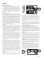
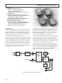
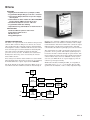
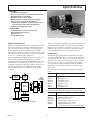
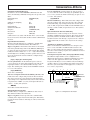
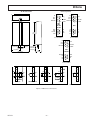
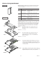
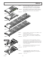
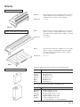
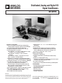
a
ANALOG l/O FEATURES
• Sensor-to-Computer Conditioning and Digitizing
Complete Data Acquisition System in Each Module
• PC to Backplane Communication: RS-232C
• Backplane and Module Communication: RS-485
• Field Configurable via Software
6B11, 6B11HV: J, K, T, E, R, S and B Thermocouple,
615 mV to 65 V, 4-20 mA, 0-20 mA
6B12, 6B12HV: 6150 mV to 650 V, 4-20 mA,
0-20 mA
6B13, 6B13HV: 100 V Pt, 120 V Ni and 10 V Cu
6B21: 0-20 mA or 4-20 mA Output
• “Simultaneous Sampling” Command Synchronizes
A/D Conversion on 6B11, 6B11HV, 6B12 and 6B12HV
• Configurable Parameters Stored in Module’s EEPROM
• Autocalibrating, High Performance Integrating
Converter, No Potentiometers Required
• Linearized Outputs in Engineering Units Onboard
Microcontroller Converts Digitized Thermocouple
and RTD Data to Standard Units
• Input to Output Isolation: 1500 V rms and 2500 V rms (HV)
• Meets IEEE Standard for CMV Transient Voltage
Protection (ANSI/IEEE C37.90.1-1989)
• Mix and Match Module Capability
Distributed, Analog and Digital I/O
Signal Conditioners
6B Series
• Small Package: 2.3" 3 3.1" 3 0.79" Modules Plug into
Backplane
• Easy to Install
• Easily Removable Without Disturbing Field Wiring
• All 6B Modules and Backplanes Meet the European
Union’s EMC Directive and Have the CE Approval
• Specifications Valid Over –258C to +858C
DIGITAL l/O FEATURES
• 24 Channels of Digital l/O
• Interfaces with Industry Standard Solid-State Relay
Panels
• Readback for Output Monitoring
• “Simultaneous Sampling” Command Synchronizes Input
Scanning with Analog Input Modules
• Bit or Byte Addressable
• Communication Compatible with Analog l/O Backplanes
APPLICATIONS
Distributed Data Acquisition and Control
Test Stand Automation
Machine Monitoring
Material Testing
Energy Management
Lab Data Acquisition
REV. B
Information furnished by Analog Devices is believed to be accurate and
reliable. However, no responsibility is assumed by Analog Devices for its
use, nor for any infringements of patents or other rights of third parties
which may result from its use. No license is granted by implication or
otherwise under any patent or patent rights of Analog Devices.
One Technology Way, P.O. Box 9106, Norwood, MA 02062-9106, U.S.A.
Tel: 617/329-4700
World Wide Web Site: http://www.analog.com
Fax: 617/326-8703
© Analog Devices, Inc., 1997
6B Series
GENERAL DESCRIPTION
INPUT MODULES
µP
ACTUATORS/
OUTPUTS
OUTPUT MODULES
Two 6B Series Families
The 6B Series of modules and backplanes are available in two
families of input/output voltage isolation ratings: 1500 V rms or
2500 V rms. The 6B11, 6B12, 6B13 and 6B21 modules provide
1500 V rms continuous CMV isolation. For more demanding
applications, the 6B11HV, 6B12HV and 6B13HV input modules provide 2500 V rms CMV isolation. In all other aspects,
the two families provide identical performance and specifications. The 6BP01, 6BP04 and 6BP16 backplanes are used with
the 6B11, 6B12, 6B13 and 6B21 modules and offer 1500 V rms
channel-to-channel and input/output CMV isolation. The
6BP01 and 6BP04HV backplanes are used with the 6B11HV,
6B12HV and 6B13HV modules to provide 2500 V rms channelto-channel and input/output CMV isolation.
RS-232C
CONV.
4-20mA
D/A
HOST/
PERSONAL
COMPUTER
RS-485
A/D
RS-485
SENSORS/
TRANSMITTERS
The 6B Series of modules and boards provides the hardware
needed to implement a flexible, distributed monitoring and
control application. By selecting only the modules and interfaces
needed and connecting them via RS-485, the data acquisition
and control strategy can be designed for optimum location of
the I/O as well as minimizing sensor runs. The modularity and
configurability of the 6B Series also makes them very cost
effective.
µP
BACKPLANE
Figure 1. 6B Series Analog l/O Block Diagram
This subsystem is completely compatible with the 6B Series
protocol. Connections to 16- and 24-channel solid-state relay
backplanes are via a 50 conductor ribbon cable. This allows
interfacing with inputs and outputs from 4 V to 240 V. Power
control modules that can switch up to three amps are also
available and come with a variety of ratings for low voltage
dc to 280 V ac.
Similar to the analog modules, the digital I/O subsystem has an
onboard microcontroller as well as nonvolatile memory. All the
digital channels are addressable on a byte or bit-by-bit basis. In
addition, the board can easily be configured for its address,
baud rate and checksum status.
Analog I/O
The 6B Series analog I/O modules represent a complete “sensor
to RS-485” solution. Each module performs signal conditioning,
isolation, ranging, A/D or D/A conversion and digital communications. The sensors and inputs supported include thermocouples, RTDs, millivolt, volt and current signals. The output
module can drive 0-20 mA or 4-20 mA interface valves or
actuators. All calibration, address and linearizing parameters are
stored in nonvolatile memory in the module.
DESIGN FEATURES AND USER BENEFITS
Simultaneous Sampling: This feature forces an input conversion to occur on all 6B11, 6B11HV, 6B12 and 6B12HV modules, and forces the 6B50 to scan its inputs at the same time. It
is useful in applications requiring synchronized measurement of
different input signals as well as for machine monitoring where
it is important to know the sequence of events in the case of a
machine failure.
Designed for industrial applications, the 6B Series modules
incorporate transformer-based isolation with automated surface
mount manufacturing technology for increased reliability at low
cost. All modules are fully encapsulated and identical in pinout
and size (2.3" × 3.1" × 0.75"). The 6B Series is fully specified
over the industrial temperature range of –25°C to +85°C.
These compact, rugged modules can be mixed and matched on
a 16-channel backplane for high density, remote data acquisition and control.
Configurable: Each 6B Series module is configurable through
software for many parameters including sensor type, output
format, baud rate and checksum status. This can be very useful
in laboratory and pilot plant environments where the temperature ranges and sensor types are not known beforehand. An
additional benefit is that inventory can be greatly reduced, with
fewer models of signal conditioners required for an application.
High Performance: The high quality signal conditioning,
combined with a precision A/D or D/A converter, delivers
± 0.05% accuracy including all temperature effects. For input
modules, the auto-zeroing feature of the A/D converter assures
excellent zero drift and long term stability.
Unlike conventional signal conditioners, each 6B module is a
complete microcomputer-based data acquisition system. A
major advantage of an onboard microcontroller is the ability to
reconfigure each module for various sensor types and input
ranges. This reduces the number of different models that have
to be used in a given application and carried in inventory. By
distributing the processing needs down to the node level, the host
is off-loaded for supervisory and higher level control functions.
High Noise Rejection: The 6B Series was designed to accurately process low level signals in harsh industrial environments
by providing up to 2500 V rms continuous transformer isolation. This also eliminates ground loops, protects against transients, and solves common mode voltage problems. The 6B
input modules give 160 dB of common-mode rejection and
50 dB of normal-mode rejection.
Interconnection between modules is via an RS-485 bidirectional
serial bus standard. Communications between modules and host
is in ASCII over an RS-232C link. Interface circuitry to convert
RS-232C to RS-485 is built into the backplane. Baud rates are
software programmable, and speeds up to 19.2 K baud can be
selected.
SOLID
50
STATE
RELAY CONDUCTOR
CABLE
PANELS
Digital I/O
Digital signals can be monitored and controlled in a 6B Series
RS-485 network by a 24-channel digital I/O interface board.
24-BIT
LATCHES
AND
BUFFERS
MICROCONTROLLER
RS-232C
CONV.
HOST/
PERSONAL
COMPUTER
RS-485
Figure 2. 6B Series Digital I/O Block Diagram
–2–
REV. B
Analog I/O Modules–6B Series
FEATURES
• Variety of Signal Source Inputs
Sensors: Thermocouples and RTDs
Millivolt and Voltage Sources
4-20 mA and 0-20 mA Process Current Inputs
• RS-485 Output
• Software Configurable for Ranges and Sensors
• ”Simultaneous Sampling” Command Synchronizes
A/D Conversion on 6B11 and 6B12
• All Configurable Parameters Stored in EEPROM
• Linearized Output in Engineering Units
• Mix and Match Input Capability
• Reliable Transformer Isolation: 1500 V rms or
2500 V rms CMV, 160 dB CMR, Meets ANSI/IEEE
C37.90.1–1989 CMV Transient Protection
• Input Protection: 240 V rms Continuous
DESCRIPTION
The 6B11 and 6B11HV linearize and compensate J, K, T, E, R,
S and B thermocouples, and digitize millivolt and volt ranges
from ± 15 mV to ± 5 V. The 6B12 and 6B12HV interface with
high level signals ranging from ± 150 mV to ± 50 V, and the
6B13 and 6B13HV linearize 100 Ω Pt (alphas of 0.00385 and
0.003916), 120 Ω Ni RTDs and 10 Ω Cu RTDs.
The 6B Series input modules cover all signal ranges from ±15 mV
to ± 50 V and all thermocouple and RTD types. The input
signal is conditioned and scaled by the programmable gain
amplifier and digitized by a 16-bit integrating converter under
microprocessor control. The conversion rate is 9 samples/sec,
which gives a Nyquist bandwidth of 4.5 Hz.
The 6B Series modules have a simple master-slave relationship
with the host, and respond only when spoken to. Each module
has a unique ID number stored in nonvolatile memory for
addressing. The format is ASCII, and all standard baud rates up
to 19.2 K baud are possible. Refer to the communication section
of the data sheet for a summary of the command set.
The digitized value is serially passed across a magnetically isolated
barrier (1500 V rms to 2500 V rms) and clocked in by a custom
controller chip. The onboard microcontroller then converts the
data into engineering units as determined by the channel parameters, i.e., whether the input signal was from a thermocouple,
an RTD or a process current. Between conversions, the microcontroller auto-zeros the offset and gain by monitoring the
onboard temperature and reference drift. CJC (Cold Junction
Compensation) is also performed at this stage.
INPUT
MUX
CJC
INPUT
PGA
Each 6B Series module can be recalibrated in the field or lab to
an external reference. Similarly, it can be reconfigured in the
field for a different transfer function. All user configured parameters are stored in the nonvolatile memory (EEPROM) of the
module. A low voltage reset monitor ensures reliable reset of the
module if the supply voltage drops below 4.4 volts.
RS-485
COMM
PORT
CHARGE
BALANCING
CONVERTER
CUSTOM
CMOS
CONTROLLER
CHIP
MICROCONTROLLER
FLOATING
POWER
EEPROM
+5V
GND
Figure 3. 6B Input Module Block Diagram
REV. B
–3–
RESET
6B Series
FEATURES
• Digitally Controlled Current Loop Output (12 Bits)
• Programmable Output Ranges: 0–20 mA or 4–20 mA
• Active Current Output; External Loop Power Supply
Not Required
• Common-Mode Isolation: 1500 V rms; Meets ANSI/IEEE
C37.90.1-1989 for CMV Transient Protection
• Normal Mode Output Protection: 240 V rms
• Programmable Slew Rate Limiting
• Output Monitoring and Readback for Fault Detection
APPLICATIONS
Distributed Data Acquisition and Control
Industrial Pilot Plant Control
Machine Control
Energy Management
RS-485 port to exchange command and status information. An
EEPROM is used to store calibration constants as well as configuration information. The microcontroller also controls the output
DAC through an optically isolated serial interface. The D/A
converter drives the current loop through a protected V/I converter.
GENERAL DESCRIPTION
The 6B21 is an output module in the 6B Series that provides
0 mA–20 mA or 4 mA–20 mA process currents. It is electrically and mechanically compatible with the existing modules
and backplanes. It takes a command from the host and converts
it into an isolated process current suitable for interfacing with
valves and actuators. The 6B21 was designed with fault
protection as a key objective. In addition, the actual current
flowing in the current loop can be read back by an onboard
isolated A/D converter.
The output monitor is a V/F converter whose frequency is proportional to the loop current. This variable signal frequency is
fed back to the microcontroller through an optical isolator. The
microcontroller then scales the frequency signal and returns the
current readback data to the host. A DC/DC converter generates 25 V @ 25 mA from the +5 V power supply to power the
current loop and output circuitry.
A low voltage reset monitor ensures reliable reset of the module
when the supply voltage drops below 4.7 V. In case of a brownout,
the module will revert to a preset output stored in EEPROM.
All 6B Series modules, including the 6B21, are encapsulated
and packaged in a 2.3" × 3.1" × 0.79" module. They are fully
specified over the industrial (–25°C to +85°C) temperature range.
The block diagram for the 6B21 is shown in Figure 4. An onboard microcontroller communicates with the host through an
RS-485
COMM
PORT
OPTO
ISOLATION
OUTPUT
MONITOR
MICROCONTROLLER
OPTO
ISOLATION
RESET
D/A
CONVERTER
PROTECTED
OUTPUT
STAGE
RL
EEPROM
+5V
GND
OSC.
AND
DRIVERS
ISOLATED
POWER
SUPPLIES
Figure 4. 6B21 Block Diagram
–4–
REV. B
Digital I/O–6B Series
FEATURES
• 24 Channels of Digital l/O
• Interfaces with Industry Standard Digital l/O Panels
• High Output Current Capability
• RS-232C Interface to Host (6B50-2)
• RS-485 Interface to Other 6B Series Backplanes
• Instruction Set Compatible with 6B Series
• “Simultaneous Sampling” Command Synchronizes
Input Scanning with Analog Input Modules
• Readback for Output Monitoring
APPLICATIONS
Distributed Data Acquisition and Control
Industrial Pilot Plant Control
Machine Control
Energy Management
Similar to other 6B Series backplanes, the 6B50 is available with
only an RS-485 interface (6B50-1), or with an additional RS-485/
RS-232C converter (6B50-2). The 6B50 is a 3.47" × 6.5" open
board that can be panel or rack mounted. It is fully specified
over the commercial (0°C to +70°C) temperature range.
GENERAL DESCRIPTION
The 6B50 is a digital I/O board that is compatible with the 6B
Series at the network level. It takes a command from the host
and converts it into logic levels suitable for interfacing with
industry standard optoisolated digital I/O panels. All I/O
channels can be configured for input or output, using bit or byte
addressing. In addition, the status of the port can be read back
by the host to confirm the I/O configuration.
INTERFACING
The 6B50 interfaces with industry standard single and quad
solid-state relay modules. These are available for use with inputs
and outputs from 4 V to 240 V. Power control modules can
switch up to three amps and are available in a variety of ratings
for low voltage dc to 280 V ac. Analog Devices also supplies
16- and 24-channel digital subsystems (DB-16 and DB-24)
that interface with the 6B50 through a 50 conductor flat
ribbon cable.
The block diagram for the 6B50 is shown below. An onboard
microcontroller communicates with the host to exchange
command and status information. An EEPROM is used to store
system parameters (address, baud rate, etc.) as well as I/O
configuration information. The microcontroller is interfaced to
8-bit latches and buffers for a maximum of 24 digital I/O
channels. Each channel can be individually set as an input
or output.
RS-232C/RS-485
CONVERTER
(6B50-2)
RS-485
COMM
PORT
The single-channel modules listed below plug into the DB-16
board.
50-PIN
FLAT CABLE
CONNECTOR
24-BIT
LATCH
PROM
MICROCONTROLLER
24-BIT
INPUT
BUFFER
RESET
Model
Range
IA140A
IA280A
OA140A
OA280A
ID016
ID032
OD060
AC Input, 140 V
AC Input, 280 V
AC Output, 140 V
AC Output, 280 V
DC Input, 16 V
DC Input, 32 V
DC Output, 60 V
The quad modules listed below plug into the DB-24 board.
Model
Range
OA240QA
OD60Q
IA120QA
IA240QA
ID32Q
ID16FQ
4-Channel Output, 120 V/240 V ac
4-Channel Output, 60 V dc
Input, 120 V ac or dc
4-Channel Input, 240 V ac or dc
4-Channel Input, 10 V–32 V dc
4-Channel Fast Input, 16 V dc
50 µs Turn-On Time, 100 µs Turn-Off Time
EEPROM
+5V
GND
OSC
Figure 5. 6B50 Block Diagram
REV. B
–5–
6B Series
BACKPLANES
Backplane Description
Dynamic Data Exchange (DDE) support for the 6B Series is
available from KEPware, Inc.® KEPware’s 32-bit 6B Series
device driver works in conjunction with KEPware’s DDE Server
(KEPDDE) to exchange data between DDE clients and 6B
Series modules. The KEPware DDE server supports NetDDE,
Advanced DDE, FastDDE, XL_Table, and CF_Text. Please
refer to the 6B Series User’s Manual for additional information.
The 6B Series backplanes, combined with modules, provide a
complete data acquisition system for end users. Each backplane
incorporates screw terminals for field wiring inputs and outputs
and cold junction compensation for thermocouple applications.
The communication interface is RS-232C to host PC and
RS-485 between backplanes.
COMMUNICATIONS
For flexibility in application, one, four and sixteen channel
backplanes are provided. These can be ordered either with the
standard RS-485 interface or with the optional RS-232C to
RS-485 converter. The RS-232C interface allows easy hookup
to most serial ports, while the standard RS-485 interface can be
used for daisy chaining additional backplanes. The RS-485 interface can drive a twisted pair cable up to a maximum of 4000 ft.
All 6B Series backplanes require a +5 V ± 5% power supply
for the backplane circuitry as well as the modules. A backplane
(four channel or sixteen channel) and a power supply can be
easily mounted on the AC1380 nineteen-inch rack mount kit.
All communications with 6B Series module subsystems consist
of commands generated by the host computer and responses
transmitted by the 6B Series modules. A “party line” system is
employed; all commands to the modules must contain an
address, and only the addressed module will reply. All characters transmitted or received from a module are composed of a
subset of printable ASCII characters.
Command Set
The following syntax is used to define the instruction set. All
arguments are two-character hexadecimal ASCII.
(AA)
The current address of the target module. The valid
range of addresses is 00(hex) to FF(hex).
(NN) The new address to which the module will be
reconfigured.
(TT)
The range code to be configured.
(CC)
The baud rate to be configured. Valid codes range
from 01 (300 baud) to 07 (19.2K baud).
(FF)
The code for the data format, integration time and
checksum status.
(CR)
ASCII Carriage Return.
Table I. Backplane Specifications
Model
Chan- Internels
face*
Isolation
Dimensions
Power
Consumption
6BP01-1
6BP01-2
6BP04-1
6BP04-2
6BP04HV-1
6BP04HV-2
6BP16-1
6BP16-2
1
1
4
4
4
4
16
16
2500 V rms
2500 V rms
1500 V rms
1500 V rms
2500 V rms
2500 V rms
1500 V rms
1500 V rms
4.25" × 1.37"
4.25" × 2.85"
3.47" × 6.5"
3.47" × 6.5"
3.47" × 6.5"
3.47" × 6.5"
3.47" × 17.4"
3.47" × 17.4"
Passive
150 mA
150 mA
150 mA
150 mA
150 mA
150 mA
150 mA
RS-485
RS-232C
RS-485
RS-232C
RS-485
RS-232C
RS-485
RS-232C
6B Input Module Commands
Read Data
Configuration
Span Calibration
Offset Calibration
Configuration Status
CJC Data
Simultaneous Sampling
Read Synchronized Data
*All backplanes have the RS-485, half duplex, interface.
CONFIG JUMPER
W1
RS-232C
TO/FROM
HOST
COMPUTER.
RS-232C TO
RS-485
CONVERTER
CR2 CR3
RTS LED
RS-485
REPEATER
DATA LED
+5 VOLTS
GROUND
FIELD TERMINATION
BLOCK
#(AA)(CR)
%(AA)(NN)(TT)(CC)(FF)(CR)
$(AA)0/(CR)
$(AA)1(CR)
$(AA)2(CR)
$(AA)3(CR)
#(**)
$(AA)(CR)
6B Input Module Responses
50Ω
CJC SENSOR
CURRENT SENSE
RESISTOR SOCKET
Data
Config or Cal OK
Config or Cal Error
Configuration Status
RS-485 TO NEXT BACKPLANE:
ALL SUBSEQUENT BACKPLANES MUST
BE RS-485 INTERFACE ONLY
Figure 6. 6BP16-2 Block Diagram
SOFTWARE SUPPORT
>(data)(CR)
!(AA)(CR)
?(AA)(CR)
!(AA)(TT)(CC)(FF)(CR)
6B Output Module Commands/Responses
Utility Disk: A DOS-based “Sixbccd” program and Windowsbased “6B-Win” program are included with the AC1383 (6B
Series User’s Manual). Either program is used to configure,
calibrate, test and evaluate the 6B-Series modules.
Drivers: Drivers for popular application software packages,
available from third party vendors, require little or no programming on the part of the user prior to configuring and running an
application package. Applications range from simple data collection and analysis to real-time process control and monitoring.
Operating platforms include DOS, Windows®3.1, Windows®95
and Windows®NT. Drivers are currently available for: LabVIEW™,
LabWindows/CVI™ and BridgeVIEW™ from National Instruments, LABTECH NOTEBOOK™ and CONTROL™ from
Laboratory Technologies Corporation and the FIX™ from
Intellution, Inc.
Out Data
Data Received
#(AA)(data)(CR)
>(CR)
Low Cal
Hi Cal
Count Up/Down
Store Startup Current
$(AA)0/(CR)
$(AA)1(CR)
$(AA)3(number of bits)(CR)
$(AA)4(CR)
Read Reset Status
Reset Status
$(AA)5(CR)
!(AA)S(CR)
Return Last Value
Last Value
$(AA)6(CR)
!(AA)(data)(CR)
Read Current Loop
Current in Loop
$(AA)8(CR)
!(AA)(data)(CR)
All trademarks are the property of their respective holders.
–6–
REV. B
Communications–6B Series
Digital I/O Commands/Responses
In addition to the standard CONFIG command for the 6B
Series, the following commands and responses are specific to the
6B50:
Digital Data Out
Response
#AABBDD(CR)
>(CR)
Simultaneous Sampling
Response
#**
None
Digital Data In
Synchronized Data In
Response
$AA6(CR)
$AA4(CR)
!DDDDDD(CR)
Reset Status
Response
$AA5(CR)
!AAS(CR)
S indicates the reset status of the module. If S = 1, the module
has been reset since the last time the Reset Status command was
executed.
Input Module Data Formats
6B Series input modules may be configured to transmit their
data in any of three different formats. The formats are:
Engineering Units: This format scales all data to the natural
units of the particular range such as volts, millivolts, milliamperes
or degrees C. Data is presented in a signed, fixed digit decimal
format; the format consists of a “+” or “–” sign, followed by five
decimal digits and a decimal point whose position varies according to the specifications associated with the configured range.
The syntax is:
(sign)(5 digits plus decimal point)
Percent of Full Scale: In this format the span is scaled to
± 100%; therefore, the data returned indicates the value of the
input signal relative to the calibrated full-scale range of the
input. The decimal point is fixed, and the maximum resolution
is ± 0.01%. The syntax is:
Percent of Full Scale: In this format, the span is scaled to
0%–100%. For the 0 mA–20 mA range, the permissible span is
0% to +110%, and for the 4 mA–20 mA range, the span is –20%
to +110%. The syntax is:
(sign)NNN.nn
Hexadecimal Binary: This format is the most compact with
the least resolution. The data is presented as a three character
hexadecimal string, representing a binary value. Positive full
scale (20 mA) is represented as FFF, and the minimum value of
the range (0 mA or 4 mA) is represented as 000. The syntax is:
HHH
Optional Checksum Generation/Checking
Checksum can be enabled to improve the detection of errors
and make communications more reliable. The syntax described
previously assumes checksum disabled. When enabled, the
modulo-256 sum of the message (expressed in two character
hexadecimal form) is added at the end, before the carriage
return.
“Simultaneous Sampling” Command
This is an unaddressed command that forces an input conversion to occur on all 6B11 and 6B12 modules and forces the
6B50 to scan its inputs. The data is held in a separate register
and can be retrieved using a separate data command. See User’s
Manual for more details.
Selecting the Integration Time (Analog Input Modules Only)
The 6B Series input modules can be configured for two
different integration times to maximize normal mode rejection
of line noise. For applications in the U.S.A. (60 Hz), the
integration time may be set for 50 milliseconds; and in Europe
(50 Hz), it may be set for 60 milliseconds. This corresponds to
three line cycles and results in a throughput of 9.5 conv/sec or
8.33 conv/sec, respectively.
(sign)(DDD.DD)
where D is a decimal digit.
The Twos Complement Hexadecimal Binary Format: This
format is the most compact and provides the most resolution.
The data is presented as a four character hexadecimal string,
representing a twos complement binary value. Positive full scale
is represented as “7FFF” (+32,767) and negative full scale as
“80/ 0/ 0/” ( –32,768). The syntax is:
7
6
5
4
3
2
T (int)
CHECK
SUM
SLEW
SLEW
SLEW
SLEW
1
6B21 ONLY
0: CHECKSUM DISABLED
1: CHECKSUM ENABLED
0: T (int) = 50ms (60Hz Operation)
1: T (int) = 60ms (50Hz Operation)
(HHHH)
where H is a hexadecimal character.
0
FORMAT FORMAT
ANALOG
INPUTS
ONLY
00: ENGINEERING UNITS
01: % OF FS
10: HEX BINARY
11: ERROR OR OHMS (6B13)
0000: IMMEDIATE
0001: 0.125mA/sec
0010: 0.250
0011: 0.500
0100: 1
0101: 2
0110: 4
0111: 8
1000: 16
1001: 32
1010: 64
1011: 128
Output Module Data Formats
Figure 7. Configuration Character
The 6B21 may be configured to communicate data in any of
three different formats. The formats are:
Engineering Units: Data is presented in a decimal format
consisting of five digits and a fixed decimal point. This format
provides the most resolution. The range is 0 mA to 22 mA. The
syntax is:
NN.nnn
REV. B
–7–
6B Series
Input Module Specifications (Typical @ +258C and +5 V power)
Model
6B11, 6B11HV
Input Types
Thermocouple, mV,
V, mA
Output
RS-485
± 0.05% or Better
Accuracy1
Zero Drift
± 0.3 µV/°C
Span Drift
± 3 ppm/°C
(± 25 ppm/°C max)
Common-Mode Voltage, Input to Output
1500 V rms Continuous
2500 V rms (HV)
Common-Mode Rejection @ 50 Hz or 60 Hz 160 dB
1 kΩ Source Imbalance
Normal-Mode Rejection @ 50 Hz or 60 Hz
58 dB
Differential Input Protection
240 V rms Continuous
Input Transient Protection (CMV)
ANSI/IEEE C37.90.1-1989
Input Resistance
100 MΩ
Bandwidth
4 Hz
Conversion Rate
9 samples/sec
Power Consumption
0.5 W
6B12, 6B12HV
6B13, 6B13HV
mV, V, mA
Pt, Ni, Cu RTD
*
*
*
± 10 ppm/°C
(± 50 ppm/°C max)
*
**
108 dB
*
± 0.03°C (Pt, Ni)
56 dB
*
*
1 MΩ
*
*
*
}
Combined Effect: ± 0.005°C/°C
*
**
*
*
*
*
N/A
*
*
*
Output Module Specifications (Typical @ +258C and +5 V power unless otherwise noted)
Model
OUTPUT SPECIFICATIONS
Ranges
Overrange
Initial Accuracy
Output Offset
Span
Accuracy vs. Temperature
Output Offset TC
Gain TC
Resolution
Nonlinearity
Bandwidth
Settling Time
Noise (100 Hz Bandwidth)
Load Resistor
Normal-Mode Protection
Slew Rate
6B21
0–20 mA, 4–20 mA
+2 mA ± 200 µA
± 5 µA (± 15 µA max)
± 0.02% FSR (± 0.05% FSR max)
± 1 µA/°C
± 50 ppm/°C
± 0.02% FSR
± 0.02% FSR
100 samples/sec
1 ms to 0.1% FSR
1 µA p-p
0 Ω to 750 Ω
240 V rms
Step Response Plus 0.125 mA–128 mA/sec in Eleven Binary Ranges
READBACK SPECIFICATIONS
Initial Accuracy
Output Offset
Span
Accuracy vs. Temperature
Output Offset TC
Gain TC
Resolution
Nonlinearity
± 5 µA/°C
± 200 ppm/°C
± 0.5% FSR
± 0.5% FSR
ISOLATION SPECIFICATIONS
Common-Mode Voltage Input to Output
CMR @ 60 Hz
Transient Protection
1500 V rms
90 dB min
ANSI/IEEE C37.90.1-1989
POWER CONSUMPTION
1.2 W
± 100 µA
± 0.5% FSR
NOTES
1
See Range Accuracy table on next page for specific accuracy by range.
*Specifications same as 6B11.
**Specifications same as 6B11HV.
Specifications subject to change without notice.
–8–
REV. B
6B Series
Range Accuracy (Typical @ +258C and +5 V power)
Hex
Code
Range Description
Typical
Accuracy1
Maximum
Error1
Peak-to-Peak
Noise
Units
00
01
02
03
04
05
06
0E
0F
10
11
12
13
14
6B11, 6B11HV
± 15 mV
± 50 mV
± 100 mV
± 500 mV
±1 V
±5 V
± 20 mA2
J Thermocouple, 0°C to 760°C
K Thermocouple, 0°C to 1000°C
T Thermocouple, –100°C to 400°C
E Thermocouple, 0°C to 1000°C
R Thermocouple, 500°C to 1750°C
S Thermocouple, 500°C to 1750°C
B Thermocouple, 500°C to 1800°C
± 0.03
+0.015
± 0.0055
± 0.005
± 0.005
± 0.005
± 0.008
± 0.4
± 0.5
± 0.5
± 0.5
± 0.63
± 0.62
± 1.2
± 0.06
± 0.04
± 0.03
± 0.03
± 0.03
± 0.03
± 0.03
± 0.75
± 0.75
± 0.75
± 0.75
± 1.5
± 1.5
± 2.0
± 0.02
± 0.01
± 0.005
± 0.002
± 0.005
± 0.0015
± 0.005
± 0.14
± 0.22
± 0.2
± 0.2
± 0.3
± 0.4
± 0.7
% of FS
% of FS
% of FS
% of FS
% of FS
% of FS
% of FS
°C
°C
°C
°C
°C
°C
°C
07
08
09
0A
0B
0C
0D
6B12, 6B12HV
± 50 V
± 10 V
±5 V
±1 V
± 500 mV
± 150 mV
± 20 mA2
± 0.006
± 0.006
± 0.006
± 0.006
± 0.01
± 0.03
± 0.006
± 0.03
± 0.03
± 0.03
± 0.03
± 0.04
± 0.06
± 0.03
± 0.004
± 0.005
± 0.006
± 0.007
± 0.008
± 0.02
± 0.007
% of FS
% of FS
% of FS
% of FS
% of FS
% of FS
% of FS
20
21
22
23
24
25
26
27
28
29
2A
2B
6B13, 6B13HV
Pt, –100°C to +100°C, a = 0.00385
Pt, 0°C to +100°C, a = 0.00385
Pt, 0°C to +200°C, a = 0.00385
Pt, 0°C to +600°C, a = 0.00385
Pt, –100°C to +100°C, a = 0.003916
Pt, 0°C to +100°C, a = 0.003916
Pt, 0°C to +200°C, a = 0.003916
Pt, 0°C to +600°C, a = 0.003916
Ni, –80°C to +100°C
Ni, 0°C to +100°C
Cu, 0°C to +120°C, = 0 Ω @ 25°C
Cu, 0°C to +120°C, = 10 Ω @ 25°C
0.02
0.03
0.03
0.05
0.03
0.05
0.03
0.04
0.05
0.03
0.13
0.11
0.15
0.15
0.15
0.15
0.15
0.15
0.15
0.15
0.15
0.15
1.4
1.4
0.03
0.04
0.04
0.05
0.03
0.03
0.04
0.05
0.02
0.02
0.04
0.04
°C
°C
°C
°C
°C
°C
°C
°C
°C
°C
°C
°C
± 0.25
± 0.5
± 0.0125
± 0.75
See
Note 1
AC1361 (CJC Sensor)
@ +25°C Ambient
Over +5°C to +45°C Ambient
°C
°C
°C/°C
NOTES
1
Module only. When measuring thermocouple signals, the CJC sensor accuracy should be added to the 6B11 and 6B11HV module accuracy to compute the average
system accuracy. The AC1361 CJC sensor is provided on each channel of the 6B Series backplanes.
2
Excluding error contribution from current sense resistor.
Common Module Specifications
POWER SUPPLY
Voltage, Operating
+5 V dc ± 5% (+6.5 V dc max)
SIZE
2.3" × 3.1" × 0.79" (58.4 × 78.7 × 19.1 mm)
ENVIRONMENTAL
Temperature Range
Rated Performance
Storage
Relative Humidity
(MIL-STD-883C, Method 1004.4)
REV. B
–25°C to +85°C
–40°C to +85°C
0°C to 95% @ +60°C
–9–
6B Series
Digital I/O Specifications (Typical @ +258C and +5 V power unless otherwise noted)
Model
6B50
DIGITAL I/O
Number of I/O
I/O Circuit Configuration
Digital Inputs
High Level Input
Low Level Input
Digital Outputs
High Level Output Current
Low Level Output Current
High Level Output Voltage
24 (Configurable for Input or Output)
Open Collector Outputs with 47 kΩ Pullups to +5 V
3.5 V min, 5.25 V max
0.8 V max
50 µA @ 5 V
100 mA @ 1.1 V
5.25 V max
COMMUNICATIONS
RS-232C (6B50-2)
Baud Rates
Maximum Distance
RS-485
Baud Rates
Maximum Distance
300, 600, 1200, 2400, 4800, 9600, 19.2 K
50 ft.
300, 600, 1200, 2400, 4800, 9600, 19.2 K
4000 ft.
POWER SUPPLY
Voltage, Operating
Voltage, Max Safe Limit
Current, Quiescent
+5 V ± 5%
+6.5 V dc
100 mA*
SIZE
3.47" × 6.5" (90.68 mm × 165.1 mm)
ENVIRONMENTAL
Temperature Range
Rated Performance
Storage
Relative Humidity
0 to +70°C
–40°C to +85°C
0 to 95%
NOTES
*Excluding load current.
Specifications subject to change without notice.
CAUTION
ESD (electrostatic discharge) sensitive device. Electrostatic charges as high as 4000 V readily
accumulate on the human body and test equipment and can discharge without detection.
Although the 6B Series features proprietary ESD protection circuitry, permanent damage may
occur on devices subjected to high energy electrostatic discharges. Therefore, proper ESD
precautions are recommended to avoid performance degradation or loss of functionality.
WARNING!
ESD SENSITIVE DEVICE
RS-485 FROM PREVIOUS
BACKPLANE (ON 6B50-1 ONLY)
RS-232C
(ON 6B50-2 ONLY)
+5 VOLTS DC
POWER
50-PIN
FLAT CABLE
CONNECTOR
50
CONDUCTOR
CABLE
(CAB-03)
DB-16
OR
DB-24
BACKPLANE
RS-485 TO NEXT
BACKPLANE
Figure 8. 6B50 Digital I/O Board Block Diagram
–10–
REV. B
6B Series
6B Module Outline
Pin Designations
NC
25
XCV–
23
RTS–
21
PWR COM
19
NC
25
XCV–
23
RTS–
21
XCV+
24
22
RTS+
20
+5V PWR
18
CONFIG
PWR COM
19
6B11
6B12
6B11HV
6B12HV
3.020
(76.71)
IN LO
7
–EXC
5
CJC EXC
3
–SNS
1
6
IN HI
4
+EXC
2
+SNS
NC
25
XCV–
23
RTS–
21
0.170 (4.32)
0.220 (5.59)
0.320 (8.13)
+5V PWR
18
CONFIG
LO
7
NC
5
NC
3
NC
1
6
HI
4
NC
2
NC
19
24
XCV+
22
RTS+
20
+5V PWR
18
CONFIG
6B13
6B13HV
0.790
(20.07)
2.280 (57.91)
RTS+
20
TOP VIEW
NC = NO CONNECT
PWR COM
1.115 (28.32)
XCV+
22
6B21
TOP VIEW
NC = NO CONNECT
0.350 0.475
(8.89) (12.07)
24
RTD COM
7
NC
5
NC
3
NC
1
6
+SNS
4
+SRC
2
NC
TOP VIEW
NC = NO CONNECT
1
1
2
2
3
50Ω
1
LO
3
2
LO
3
HI
1
1
2
2
3
RL
3
HI
4
PLUG
IN
RESISTOR
(AC1381)
4-20mA
4
4
2 WIRE
THERMOCOUPLE
mV,V
INPUT CONNECTIONS
4
RTD
OUTPUT CONNECTIONS
Figure 9. 6B Series Connections
REV. B
4
3 & 4 WIRE
–11–
6B Series–Ordering Guide Worksheet
MODULES
Module Selection: Determine the types and number of 6B Series modules
based on sensor inputs. The following table lists the sensors and ranges
covered by each module.
Module
Range
6B11,
6B11HV
Thermocouples:
Voltage Inputs:
Current Inputs:
6B12,
6B12HV
Voltage Inputs:
Current Inputs:
BACKPLANES
6BP01-1
J, K, T, E, R, S & B
± 15 mV, ± 50 mV, ± 100 mV, ± 500 mV,
± 1 V, ± 5 V
± 20 mA (4-20 mA is a subset of this.)
± 150 mV, ± 500 mV, ± 1 V, ± 5 V, ± 10 V,
± 50 V
± 20 mA (4-20 mA is a subset of this.)
6B13
6B13HV
RTDs:
Pt 100 Ω, ∞ = 0.003916 or 0.00385
Ni 120 Ω, Cu 10 Ω
6B21
Current Output:
0-20 mA, 4-20 mA
Backplane Selection: Determine the backplanes you need according to the
number of modules chosen, the required channel-to-channel isolation and
the clustering of sensors. If the host interface is RS-232C, then one backplane
must have the RS-232C option for connecting to the host. All subsequent
daisy-chained backplanes must use the RS-485 interface. The available
backplanes are as follows:
6BP01-1
One-channel backplane with one RS-485 interface only.
Mountable in a 40 mm × 111 mm DIN holder. Requires
+5 V power.
Dimensions:
1.37" × 4.25"
6BP01-2
One-channel backplane with one RS-232C interface for
a host connection and one RS-485 interface for daisychaining. Mountable in a 75 mm × 111 mm DIN holder.
Requires +5 V power.
Dimensions:
2.85" × 4.25"
6BP01-2
6BP04-1
Four-channel backplane with two RS-485 ports: one for connecting to the previous backplane (or host) and the other for
connecting to the next backplane in the daisy chain (up to 4000
feet away). Backplane current requirement: 200 mA @ +5 V
(excluding modules).
6BP04HV-1
Same as 6BP04-1, but Isolation Voltage (input-to-output and
channel-to-channel) is 2500 V rms (vs. 1500 V rms), and Power
Supply Overvoltage Protection (>6.5 V dc) is provided.
6BP04-1
6BP04HV-1
–12–
REV. B
6B Series
6BP04-2
Four-channel backplane with an RS-232C interface for host
connection and an RS-485 interface to connect to the next
backplane in the daisy chain (up to 4000 feet away). Backplane
current requirement: 200 mA @ +5 V (excluding modules).
6BP04HV-2
Same as 6BP04-2, but Isolation Voltage (input-to-output and
channel to channel) is 2500 V rms (vs. 1500 V rms), and Power
Supply Overvoltage Protection (>6.5 V dc) is provided.
Dimensions:
3.47" × 6.5"
6BP16-1
16-channel backplane. System interface same as 6BP04-1. Power
requirement also 200 mA @ +5 V.
6BP16-2
16-channel backplane. System interface same as 6BP04-2.
Requires 200 mA @ +5 V for backplane (excluding modules).
Dimensions:
3.47" × 17.4"
6BP04-2
6BP04HV-2
6BP16-1
6BP16-2
DIGITAL I/O
6B50-1
The 6B50 provides 24 channels of digital I/O in a 6B Series
network. All channels can be individually configured for input or
output using bit or byte addressing. The 50-pin connector on the
board interfaces with industry-standard, solid-state relays (single
as well as quad modules).
6B50-1
24-channel digital I/O board with RS-485 input and output
screw terminals. Requires 225 mA @ +5 V.
Dimensions:
3.47" × 6.5"
6B50-2
24-channel digital I/O board with an RS-232C port for
interfacing with the host and a RS-485 port for expansion.
Require 225 mA @ +5 V.
Dimensions:
3.47" × 6.5"
6B50-2
REV. B
–13–
6B Series
DIRECT TTL CONNECTION
STB-50A
This panel provides screw terminals for direct connection
to all 24 TTL-level discrete I/O channels. It connects to
the 6B50 with a 3-foot ribbon cable (included).
Dimensions:
3" × 5.25"
DB-16
Provides isolated connection of high level ac or dc voltage
inputs or outputs to 16 digital I/O channels. Accommodates single channel modules. Order a CAB-03 cable with
each DB-16.
Dimensions:
3.5" × 14.05"
DB-24
Provides isolated connection of high-level ac or dc voltage
inputs or outputs to 24 digital I/O channels. Accommodates quad solid-state relay modules. Order a CAB-03
cable with each DB-24.
Dimensions:
6.0" × 8.0"
STB-50A
SOLID-STATE RELAY CONNECTION
DB-16
DB-24
The single channel modules listed below plug into the DB-16 board.
SOLID-STATE RELAY MODULES
Model
Range
IA140A
IA280A
OA140A
OA280A
ID016
ID032
OD060
AC Input, 140 V
AC Input, 280 V
AC Output, 140 V
AC Output, 280 V
DC Input, 16 V
DC Input, 32 V
DC Output, 60 V
The quad modules listed below plug into the DB-24 board.
Model
Range
OA240QA
OD60Q
IA120QA
IA240QA
ID32Q
ID16FQ
4-Channel Output, 240 V ac
4-Channel Output, 60 V dc
4-Channel Input, 120 V ac or dc
4-Channel Input, 240 V ac or dc
4-Channel Input, 10 V–60 V dc
4-Channel Fast Input, 16 V dc
50 µs Turn-On Time, 100 µs Turn-Off Time
–14–
REV. B
6B Series
Power Supply Selection: Determine the power supplies you need according to
how backplanes are grouped. All power supplies are chassis mountable. The
available power supplies are as follows:
POWER SUPPLIES
MODELS 955
AND 977
Model
Amps
Description
V ac In
955
977
PWR-01
AC1340-D
1A
5A
5A
Suitable for Up to 6 Input Modules
Suitable for Up to 32 Input Modules
Suitable for Up to 32 Input Modules
Power Cord (U.S.)
110
110
110/220
110
Dimensions: 2.7" × 4.0" × 1.45" (955,977)
2.76" × 4.7" × 1.38" (PWR-01)
PWR-01
RACK-MOUNT KITS
AC1380: The rack-mount kit mounts in a 19-inch rack and occupies 3 1/2 inches
of rack space. It will hold one 4-channel or 16-channel backplane. The power
supplies can be mounted on the underside of the rack mount.
OPTIONAL
POWER SUPPLY
AC1380
RACK MOUNT
6B SERIES
BACKPLANE
RM-02: This rack-mount kit mounts in a 19-inch rack and occupies 7 inches of
rack space. It can hold a DB-24 backplane.
RM-02
REV. B
–15–
6B Series
ACCESSORIES
AC1361: This SIP (Single-In-Line-Package) temperature sensor provides cold
junction temperature measurements for thermocouple applications on user
designed backplanes. These sensors are provided on each channel of the 6B
backplanes.
AC1381: This is a 50 Ω current conversion resistor that plugs into the backplane.
One AC1381 is required for each 4-20 mA/0-20 mA input channel of the
backplane.
AC1382: This cable connects to most PC serial ports. Only Pins 2, 3 and 7
(connected one-to-one) are required for operation.
AC1385: This cable connects to some 9-pin PC serial ports: Pins 2, 3 and 5 on
the 9-pin connector are connected to 3, 2 and 7 on the 25-pin connector.
CAB-03: This is a 50-pin ribbon cable that connects the 6B50 to a DB-16 or
DB-24 backplane.
SOFTWARE/DOCUMENTATION
6B Series Configuration Disk and Manual (AC1383): The disk is useful for
configuring the address, baud rate and range of the 6B Series modules. The
AC1383 software supports DOS, Windows 3.1, Windows 95 and Windows NT.
Application Software: Drivers for the following software packages are available
directly from the vendor. LabVIEW, LabWindows/CVI, BridgeVIEW from
National Instruments in Austin, TX; LABTECH NOTEBOOK and CONTROL
from Laboratory Technologies Corporation in Wilmington, MA; THE FIX from
Intellution in Norwood, MA.
–16–
REV. B
6B Series
TYPICAL CONFIGURATIONS
To assemble a complete 6B Series system, first consider grouping the sensors
to use the daisy-chaining capability of the system. (This will reduce sensor wire
routing and simplify host communication.) Then, select the following components of the system:
1. Hardware
– 6B Series Modules
– 6B Series Backplanes
– Power Supplies and Power Supply Cords
2. Accessories
– RS-232C Cable to Host
– Belden Cable to Interconnect Backplanes with RS-485 (Belden P/N9729)
– Current Conversion Resistor (AC1381)
– Rack-Mount Kit for 19-inch Rack
3. Software
– 6B Series Configuration Disk
– Application Software. Drivers for the following software packages are available directly from the vendor.
– LabVIEW, LabWindows/CVI, BridgeVIEW from National Instruments in Austin, TX; LABTECH
– NOTEBOOK and CONTROL from Laboratory Technologies Corporation in Wilmington, MA; THE FIX
– from Intellution in Norwood, MA.
RS-232C CABLE
(AC1385)
+5V POWER SUPPLY
MODEL 955
AC POWER
CORD (AC1340-D)
SENSOR
6BP01-2
Figure 10. One-Channel 6B Series Setup
Minimum Configuration. The setup in Figure 10 can be used to evaluate or configure a 6B Series analog module. The 6BP01-2
can also be used as an RS-232 to RS-485 converter for applications that require the first set of modules to be up to 4000 feet from
the host. The 6BP01-2 does not require a module to function as a converter.
REV. B
–17–
6B Series
HOST
COMPUTER
DB-24
DIGITAL I/O
BACKPLANE
RS-232C
PWR
6B50-1
6BP16-2
PWR
RS-485
RS-485
6BP16-1
PWR
PWR
6BP04-1
(6BP04HV-1)
RS-485
PWR
PWR
6BP01-1
6BP04-1
(6BP04HV-1)
PWR
6BP01-1
PWR
6BP01-1
Figure 11. Multiple-Backplane Configuration
Multiple-Backplane Configuration
In a setup similar to Figure 11, the following constraints on the RS-485 must be observed:
1. Maximum cable length between backplanes with repeaters (6BP04 and 6BP16) is 4000 feet.
2. Maximum loads on a segment between repeaters is 32 (1 load = one module or one 6B50).
The recommended cable for RS-485 is a dual twisted-pair with foil shield and drain (such as Belden P/N 9842).
–18–
REV. B
6B Series
Model
Description
Module
6B11, 6B11HV
6B12, 6B12HV
6B13, 6B13HV
6B21
Isolated Thermocouple, mV/V, mA Input
Isolated V, mA Input
Isolated RTD Input
Isolated Current Output
Backplane
6BP01-1
6BP01-2
6BP04-1, 6BP04HV-1
6BP04-2, 6BP04HV-2
6BP16-1
6BP16-2
Single-Channel Backplane with RS-485 Interface
Single-Channel Backplane with RS-485 and RS-232C Interfaces
4-Channel Backplane with RS-485 Interface
4-Channel Backplane with RS-485 and RS-232C Interfaces
16-Channel Backplane with RS-485 Interface
16-Channel Backplane with RS-485 and RS-232C Interfaces
Digital I/O
6B50-1
6B50-2
STB-50A
DB-16
DB-24
IA140A
IA280A
OA140A
OA280A
ID016
ID032
OD060
OD200
OA240QA
OD60Q
IA120QA
IA240QA
ID32Q
ID16FQ
24-Channel Backplane with RS-485 Interface
24-Channel Digital I/O with RS-232C and RS-485 Interface
Termination Panel for Digital I/O, DIN Rail Mounting
16-Channel Digital I/O Backplane (Single-Channel Modules)
24-Channel Digital I/O Backplane (Quad-Channel Modules)
Single-Channel Modules for the DB-16 Backplane
AC Input, 140 V
AC Input, 280 V
AC Output 140 V
AC Output, 280 V
DC Input, 16 V
DC Input, 32 V
DC Output, 60 V
DC Output, 200 V
Quad-Channel Modules for the DB-24 Backplane
4-Channel Output, 240 V ac
4-Channel Output, 60 V dc
4-Channel Input, 120 V ac
4-Channel Input, 10–32 V dc
4-Channel Input, 16 V dc
4-Channel Fast Input, 16 V dc
50 µs Turn-On Time, 100 µs Turn-Off Time
Power Supplies
955
977
PWR-01
+5 V @ 1 A Power Supply
+5 V @ 5 A Power Supply
+5 V @ 5 A Power Supply (Wide Input Range: 85 V ac to 265 V ac)
Accessories
AC1361
AC1380
AC1381
AC1382
AC1383
AC1340-D
CAB-03
Temperature Sensor for Cold Junction Compensation
19-Inch Rack Mount
50 Ω Current Conversion Resistor
RS-232C Cable
6B Series User’s Manual and Configuration Disk
Power Cord (U.S.)
50-Pin Ribbon Cable, Connects 6B50 to DB-16 or DB-24
REV. B
–19–
–20–
PRINTED IN U.S.A.
C1244b–12–4/97