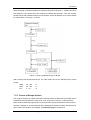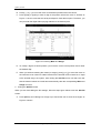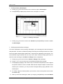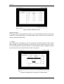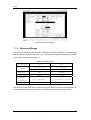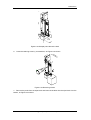
1
BC-2800
Auto Hematology Analyzer
Operation Manual
Copyright
Statement
SHENZHEN MINDRAY BIO-MEDICAL ELECTRONICS CO., LTD. (hereinafter called Mindray)
owns all rights to this unpublished work and intends to maintain this work as confidential.
Mindray may also seek to maintain this work as an unpublished copyright. This publication is
to be used solely for the purposes of reference, operation, maintenance, or repair of Mindray
equipment. No part of this can be disseminated for other purposes.
In the event of inadvertent or deliberate publication, Mindray intends to enforce its rights to
this work under copyright laws as a published work. Those having access to this work may
not copy, use, or disclose the information in this work unless expressly authorized by Mindray
to do so.
All information contained in this publication is believed to be correct. Mindray shall not be
liable for errors contained herein nor for incidental or consequential damages in connection
with the furnishing, performance, or use of this material. This publication may refer to
information and protected by copyrights or patents and does not convey any license under the
patent rights of Mindray, nor the rights of others. Mindray does not assume any liability arising
out of any infringements of patents or other rights of third parties.
Content of this manual is subject to changes without prior notice.
PROPERTY OF SHENZHEN MINDRAY BIO-MEDICAL ELECTRONICS CO., LTD.
ALL RIGHTS RESERVED
Responsibility on the manufacturer party
Mindray is responsible for safety, reliability and performance of this equipment only in the
condition that:
• all installation, expansion, change, modification and repair of this equipment are conducted
by Mindray qualified personnel;
• applied electrical appliance is in compliance with relevant National Standards;
Auto Hematology Analyzer Operation Manual(V1.0)
I
Note
This equipment is not intended for family usage.
This equipment must be operated by skilled/trained clinical personnel.
Warning
It is important for the hospital or organization that employs this equipment to carry out a
reasonable maintenance schedule. Neglect of this may result in machine breakdown or injury
of human health.
Warranty
THIS WARRANTY IS EXCLUSIVE AND IS IN LIEU OF ALL OTHER WARRANTIES,
EXPRESSED OR IMPLIED, INCLUDING WARRANTIES OF MERCHANT ABILITY OR
FITNESS FOR ANY PARTICULAR PURPOSE.
Exemptions
Mindray's obligation or liability under this warranty does not include any transportation or
other charges or liability for direct, indirect or consequential damages or delay resulting from
the improper use or application of the product or the substitution upon it of parts or
accessories not approved by Mindray or repaired by anyone other than a Mindray authorized
representative.
This warranty shall not extend to any instrument which has been subjected to misuse,
negligence or accident; any instrument from which Mindray's original serial number tag or
product identification markings have been altered or removed, or any product of any other
manufacturer.
Return Policy
Return Procedure
In the event that it becomes necessary to return a unit to Mindray, the following procedure
should be followed:
1.
Obtain return authorization. Contact the Mindray Service Department and obtain a
Customer Service Authorization (Mindray) number. The Mindray number must appear on
the outside of the shipping container. Return shipments will not be accepted if the
Mindray number is not clearly visible. Please provide the model number, serial number,
II
Auto Hematology Analyzer Operation Manual(V1.0)
and a brief description of the reason for return.
2.
Freight policy. The customer is responsible for freight charges when equipment is
shipped to Mindray for service (this includes customs charges).
Company Contact
Address:
Mindray Building, Keji 12th Road South, Hi-tech Industrial
Park, Nanshan, Shenzhen 518057 P.R.China
Free hot line:+86 800 830 3312
Phone:
+86 755 26582888
Fax:
+86 755 26582680
Auto Hematology Analyzer Operation Manual(V1.0)
III
Safety Symbols
Symbol
Warning Condition
Action
Consider all materials Wear standard laboratory
attire, glove and follow safe
controls, calibrators, or laboratory procedures when
Biohazard:
(specimens,
components that contain or have contacted handling any material in the
human blood) as being potentially laboratory.
infectious.
any
unnecessary
The probe is sharp Avoid
contact with the probe and
and may contain biohazardous materials, probe area.
Probe Hazard:
including controls and calibrators.
NOTE:
information
Indicate
of
to
the
importance
operator
in
the
procedure to be performed. This heading is
also used to indicate specific sample
handling techniques that are helpful in
operating the instrument.
CAUTION:
Indicate to the operator
information of importance that could result
in damage to the instrument or affect the
test due to improper operation if these
instructions are not followed.
WARNING:
Indicate to the operator
information regarding potential hazards
that may cause personal harm to the
operator if these instructions are not
followed.
Auto Hematology Analyzer Operation Manual(V1.0)
1
(1)
(2)
(3)
(1)
WARNING
To avoid electrical
shock, be sure to
disconnect the power
supply
before
maintaining
this
device.
(2)
BIOHAZARD
Consider waste that contain or have contacted
human blood as being potentially infectious.
Wear laboratory attire, glove and follow safe
laboratory procedures when handling any
material in the laboratory.
2
Auto Hematology Analyzer Operation Manual(V1.0)
(3)
Equipotentiality.
(4)
(4)
WARNING
To
avoid
being
injured, do not put
hand under the motor
when the machine is
running.
Auto Hematology Analyzer Operation Manual(V1.0)
3
(5)
(6)
(5)and(6)
WARNING
To avoid electrical shock, be sure to disconnect the
power supply before maintaining this device.
FOR IN VITRO DIAGNOSTIC USE
BATCH CODE
USE BY
CE MARK
DATE OF MANUFACTURE
4
Auto Hematology Analyzer Operation Manual(V1.0)
MANUFATURER
AUTHORISED REPRESENTATIVE IN THE EUROPEAN COMMUNITY
SERIAL NUMBER
Auto Hematology Analyzer Operation Manual(V1.0)
5
MANUFATURER
AUTHORISED REPRESENTATIVE IN THE EUROPEAN COMMUNITY
SERIAL NUMBER
Auto Hematology Analyzer Operation Manual(V1.0)
5
Content
Content
Chapter 1
Introduction ....................................... 1-1
1.1
Foreword ...................................................................................................................... 1-1
1.2
General ......................................................................................................................... 1-2
1.3
System Introduction ................................................................................................... 1-3
1.4
Principles of Operation............................................................................................... 1-6
1.5
Specifications ............................................................................................................ 1-11
1.6
System Operation ..................................................................................................... 1-15
1.7
Operation Summary.................................................................................................. 1-22
Chapter 2
Installation ........................................... 2-1
2.1
Unpacking .................................................................................................................... 2-1
2.2
Installation Requirements .......................................................................................... 2-2
2.3
Installation ................................................................................................................... 2-3
2.4
Loading Recording Paper .......................................................................................... 2-6
2.5
Installing Printer .......................................................................................................... 2-8
2.6
Installing Scanner (optional)...................................................................................... 2-9
Chapter 3
Sample Analysis ........................................ 3-1
3.1
Preparing to Start ........................................................................................................ 3-1
3.2
Power-up ...................................................................................................................... 3-3
3.3
Entering Count Screen ............................................................................................... 3-4
3.4
Entering Sample Information ..................................................................................... 3-7
3.5
Preparing Samples.................................................................................................... 3-15
3.6
Sample Analysis........................................................................................................ 3-17
3.7
Background Check ................................................................................................... 3-25
3.8
Shutdown ................................................................................................................... 3-26
Chapter 4
Quality Control ........................................ 4-1
4.1
QC with Controls......................................................................................................... 4-2
4.2
X-B Analysis .............................................................................................................. 4-12
Chapter 5
Calibration ........................................... 5-1
5.1
Introduction ................................................................................................................. 5-1
5.2
Preparing for Calibration............................................................................................ 5-2
Auto Hematology Analyzer Operation Manual(V1.0)
I
Content
5.3
Manual Calibration ...................................................................................................... 5-3
5.4
Calibration Using Calibrators .................................................................................... 5-8
5.5
Calibration Using Fresh Blood ................................................................................ 5-15
Chapter 6
Sample Review ........................................ 6-1
6.1
Histogram Mode .......................................................................................................... 6-2
6.2
Review in Table Mode ................................................................................................. 6-5
Chapter 7
Setup .............................................. 7-1
7.1
Password ..................................................................................................................... 7-1
7.2
Editing Settings........................................................................................................... 7-4
Chapter 8
Maintenance .......................................... 8-1
8.1
Regular Maintenance .................................................................................................. 8-1
8.2
System Maintenance................................................................................................... 8-3
8.3
System Status............................................................................................................ 8-16
8.4
System Self-Test........................................................................................................ 8-18
8.5
Log.............................................................................................................................. 8-22
8.6
System Configuration............................................................................................... 8-24
8.7
Printing Management................................................................................................ 8-25
8.8
Adjusting Sample Probe and Probe Wipe Block ................................................... 8-27
Chapter 9
Troubleshooting ....................................... 9-1
9.1
Error Codes.................................................................................................................. 9-2
9.2
Solutions ...................................................................................................................... 9-3
Appendix A
Communication ...................................... A-1
A.1
Connection...................................................................................................................A-1
A.2
Setting Transmission Parameters .............................................................................A-1
A.3
Transmission ...............................................................................................................A-2
A.4
Transmission Date Format .........................................................................................A-2
II
Auto Hematology Analyzer Operation Manual(V1.0)
Introduction
Chapter 1
Introduction
1.1 Foreword
This manual covers all the instructions related to the operation and general maintenance of the
BC-2800 Auto Hematology Analyzer. To ensure this analyzer performs in the best way, please
carefully read and comprehend the contents of this manual and operate/maintain this analyzer
exactly as instructed.
This manual includes a detailed description of this analyzer, the specifications given by the
manufacturer, methods to install, calibrate and maintain this analyzer, and measures to be
taken when errors occur. It also presents the working principle of this analyzer and the
recommended reagents.
Operation notes, limits and potential hazards are stressed where appropriate.
This chapter mainly deals with the following contents:
General
Introduces how this manual is organized and presents a brief introduction of all the chapters.
System introduction
Briefly introduces the main factors of this analyzer, including functions, accessories and
optional parts.
Principles of operation
Introduces how the analyzer functions.
Specifications
Presents the specifications of this analyzer.
System operations
Describes the key functions, display areas and system menu and presents a brief introduction
of how to operate this analyzer.
Auto Hematology Analyzer Operation Manual(V1.0)
1-1
Introduction
1.2 General
See Table 1-1 for the organization of this manual and brief introductions of the chapters.
Table 1-1 Organization of the BC-2800 operation manual
Chapters
Contents
Chapter 1 Introduction
Introduces
organization
of
this
manual,
system introduction, principles of operation,
specifications,
system
operations
and
requirements
and
operation summary.
Chapter 2 Installation
Introduces
installation
steps.
Chapter 3 Sample Analysis
Introduces how to analyze samples on this
analyzer.
Chapter 4 Quality Control
Introduces how to run the QC program on this
analyzer.
Chapter 5 Calibration
Introduces how to calibrate this analyzer.
Chapter 6 Sample Review
Introduces how to review, search and print the
saved sample analysis results.
Chapter 7 Setup
Introduces how to set date, time and other
system settings.
Chapter 8 Service
Introduces how to maintain this analyzer and
replace the reagents.
Chapter 9 Troubleshooting
Introduces how to deals with the reported
errors.
Appendix A Communication
1-2
Communication protocol.
Auto Hematology Analyzer Operation Manual(V1.0)
Introduction
1.3 System Introduction
1.3.1 Name and Intended Use
The full name of this analyzer is BC-2800 Auto Hematology Analyzer. It is a quantitative,
automated hematology analyzer and leukocyte differential counter for In Vitro Diagnostic Use
in clinical laboratories.
Note
The purpose of this analyzer is to identify the normal patient, with all
normal system-generated parameters, and to flag or identify patient
results that require additional studies.
It determines the following 19 hematological parameters and presents 3 histograms of blood
specimens.
Table 1-2 Parameters and histograms
Group
Parameter
Abbreviation
WBC Group
White Blood Cell or leukocyte
WBC
Lymphocyte
Lymph#
Mid-sized cell
Mid#
Granulocyte
Gran#
Lymphocyte percentage
Lymph%
Mid-sized cell percentage
Mid%
Granulocyte percentage
Gran%
WBC histogram
HGB Group
Hemoglobin Concentration
HGB
RBC Group
Hemoglobin Concentration
RBC
Hematocrit
HCT
Mean Corpuscular (erythrocyte)
MCV
Volume
Mean
Cell
(erythrocyte)
MCH
(erythrocyte)
MCHC
Hemoglobin
Mean
Cell
Hemoglobin Concentration
Red
Blood
Cell
(erythrocyte)
RDW-CV
Distribution Width
Coefficient of Variation
Auto Hematology Analyzer Operation Manual(V1.0)
1-3
Introduction
Red
Blood
Cell
(erythrocyte)
RDW-SD
Distribution Width
Standard Deviation
RBC histogram
PLT Group
Platele
PLT
Mean Platelet Volume
MPV
Platelet Distribution Width
PDW
Plateletcrit
PCT
PLT histogram
1.3.2 Classifications
CE: General In vitro diagnostic medical devices
1.3.3 Supplementary Data
Mindray aperiodically issues and delivers supplementary documents pertaining to operation or
maintenance of this instrument. Be sure to read and observe these documents carefully and
precisely as well as insert them into this manual for convenient reference。
1.3.4 Service Assistance
If this analyzer does not operate properly, follow the directions in Chapter 9, Troubleshooting.
If the error cannot be corrected by the recommended methods, contact the Mindray Customer
Service Department or the distributor
1.3.5 Reagents, Calibrators and Controls
The reagents, controls, calibrators, and analyzer are components of a whole system and must
be used as one. Be sure that any products to be used have been tested and certified by the
manufacturer.
Mindray recommends the reagents described in Chapter 1.5.10 Reagents. Do not use the
reagents or controls from different suppliers, or else the analyzer may not perform as promised
and even be damaged.
Each reagent should be examined prior to its application. Product integrity may be
compromised in damaged containers. If a package appears damaged, inspect the inside for
signs of leakage or moisture and find them, do not use the reagent. Read the user’s
instructions of the reagents and operate as instructed when using the reagents.
otherwise specified, reagents must be stored and used at room temperature.
1-4
Auto Hematology Analyzer Operation Manual(V1.0)
Unless
Introduction
Note
To properly and safely use the reagents, be sure to read the tags
on the package and the supplied data sheet.
1.3.5.1
Reagents
1. Diluent
Besides diluting the blood sample, the diluent provides an environment similar to blood plasma
to keep the sizes of blood cells unchanged within a certain period of time and serves as a
conductive media for blood cells analysis.
2. Lyse
The lyse can rapidly break down the red blood cell membranes and reduce cellular debris to a
size small enough so that it does not interfere with white blood cell analysis. White cells can
then be segregated into three sub-populations for differential analysis.The absorbency of the
lyse-hemoglobin mixture is determined by the hemoglobin.
3. Rinse
The rinse is a detergent used to wash the tubing and wet the volumetric tube.
4. E-Z Cleanser
The Enzymatic Cleanser is an enzyme based, isotonic cleaning solution and wetting agent
used to rinse the tubing and bath. This cleanser will not damage the plastic parts of the
analyzer.
5. Probe Cleanser
The probe cleanser is used to maintain the analyzer.
1.3.5.2
Calibrators and Controls
Calibrators and controls are whole blood products manufactured to calibrate and verify the
operation of instruments.
The “calibrators” and “controls” that appear in the rest of this manual refer to the calibrators
and controls to be used on this analyze only. You shall order them only from Mindray customer
service department or the distributor.
Auto Hematology Analyzer Operation Manual(V1.0)
1-5
Introduction
1.4 Principles of Operation
1.4.1 Measuring Principle
This analyzer adopts the Coulter Principle to count WBC, RBC and PLT cells and to draw their
corresponding histograms. The Hemoglobin concentration (HGB) is obtained by the
colorimetric method. The result of the rest parameters are derived from those (see Chapter
1.4.4, Derivation of Parameters).
1.4.2 Dilution
Usually in blood specimens, the cells are too close to each other to be identified or measured.
For this reason, the diluent is used to separate the cells so that they are drawn through the
aperture one at a time as well as to create a conductive environment for blood analysis. This
analyzer can processes two types of blood samples – whole blood samples (see Chapter
2.5.1 Preparing Whole Blood Samples) and prediluted blood samples (see Chapter 2.5.2
Preparing Prediluted Samples). When analyzing a whole blood sample, this analyzer
aspirates 13μL of the sample and follow the procedure presented in Figure 1-1 to dilute it
before proceeding to the actual analysis.
Figure 1-1 How a whole blood sample is diluted
1-6
Auto Hematology Analyzer Operation Manual(V1.0)
Introduction
When analyzing a prediluted sample, the operator should first collect 20μL capillary specimen
and dispense 1.6mL diluent from this analyzer to predilute the specimen. Then the operator
should present the prediluted sample to the analyzer, which will aspirate 0.7ml of the sample
for further dilution, as Figure 1-2 shows.
Figure 1-2 How a prediluted sample is diluted
After reacting with the diluent and lyse, the cells mainly fall into the following three volume
ranges:
WBC:
30~350
fL
RBC:
25~250
fL
PLT:
2~30
fL
1.4.3 Control of Sample Volume
This analyzer employs an optical volumetric metering system to determine the sample volume
aspirated through the aperture. Each count cycle, as shown in Figure 1-3, starts when the
liquid surface passes the upper sensor of the volumetric tube and ends till the lower sensor is
reached. If bubbles or an abnormal flow rate is detected, the system will alarm the operator for
errors. When this happens, see Chapter 9 Troubleshooting for the solutions.
Auto Hematology Analyzer Operation Manual(V1.0)
1-7
Introduction
Upper sensor
Upper sensor
Lower sensor
Lower sensor
1 Empty when start
2 Liquid surface fall down through the
volumeritc tube
Upper sensor
Upper sensor
Lower sensor
Lower sensor
3 Counting start when the
liquid surface pass the upper
sensor.
4 Counting end when the liquid
surface pass the lower sensor
Figure 1-3 How sample volume is controlled
1.4.4 Derivation of Parameters
1.4.4.1
WBC
9
WBC(10 / L) is the number of leukocytes measured directly by counting the white blood cells
passing through the aperture. Note that when you observe in the microscope NRBCs
(nucleated red blood cells), which do not react with the lyse and can be mistaken by the
analyzer for white cells, be sure to correct the system-generated result by the following
formula,
WBC '=WBC ×
100
100+NRBC
where WBC represents the system-generated white cell number, NRBC the number of NRBCs
counted in 100 white cells and WBC′ the corrected white cell number.
1.4.4.2
WBC differential
With the help of the diluent and lyse, this analyze can size the white cells into three
sub-populations - lymphocytes, mid-sized cells, and granulocytes.
Lymphocytes are the largest white cells whose sizes are 30fL~85fL. Granulocytes are the
smallest white cells whose sizes are above 125fL. Between them are the mid-sized cells
whose sizes are 85fL~125fL.
1-8
Auto Hematology Analyzer Operation Manual(V1.0)
Introduction
Based on the WBC histogram, this analyzer calculates Lymph%, Mid% and Gran% as
follows,
(Lymph% )(%) =
PL
× 100
PL + PM + PG
PM
(Mid % )(%) =
× 100
PL + PM + PG
(Gran% )(%) =
PG
PL + PM + PG
× 100
9
where PL = particles in the lymphocyte region( 10 / L )
9
PM = particles in the mid size region( 10 / L )
9
PG = particles in the granulocyte region( 10 / L ).
Having achieved the three parameters above, this analyzer proceeds to calculate the Lymph# ,
Mid# and Gran# as follows.
Lymph# (10 9 / L) =
Mid # (10 9 / L) =
Gran# (10 9 / L) =
1.4.4.3
Lymph%(%) × WBC (10 9 / L)
100
Mid %(%) × WBC (10 9 / L)
100
Gran%(%) × WBC (10 9 / L)
100
HGB
Using the colorimetric method, this analyzer calculates hemoglobin concentration (g/L) as
follows.
HGB(g/L)=Constant×Log 10 (Blank Photocurrent/Sample Photocurrent)
1.4.4.4
RBC
12
RBC (10 /L)is the number of erythrocytes measured directly by counting the erythrocytes
passing through the aperture.
1.4.4.5
MCV
Based on the RBC histogram, this analyzer calculates the mean cell volume (MCV) and
expresses the result in fL .
Auto Hematology Analyzer Operation Manual(V1.0)
1-9
Introduction
1.4.4.6
HCT, MCH and MCHC
This analyzer calculates the HCT (%), MCH(pg) and MCHC(g/L) as follows:
RBC (1012 / L) × MCV ( fL)
10
HGB( g / L)
MCH ( pg ) =
RBC (1012 / L)
HCT (%) =
MCHC(g / L) =
1.4.4.7
HGB(g / L)
× 100
HCT (%)
RDW-CV
Based the WBC histogram, this analyzer calculates the CV (Coefficient of Variation) of the
erythrocyte distribution width.
1.4.4.8
RDW-SD
RDW-SD (RBC Distribution Width – Standard Deviation, fL) is set on the 20% frequency level
with the peak taken as 100%, as Figure 1-4 shows.
Figure 1-4 RBC Distribution Width – Standard Deviation
1.4.4.9
PLT
9
PLT (10 /L) is measured directly by counting the platelets passing through the aperture.
1.4.4.10 MPV
Based on the PLT histogram, this analyzer calculates the mean platelet volume (MPV, fL).
1.4.4.11 PDW
Based on the PLT histogram, this analyzer calculates the platelet distribution width (PDW).
1.4.4.12 PCT
This analyzer calculates the PCT as follows.
PLT (10 9 / L) × MPV ( fL)
PCT (%) =
10000
1-10
Auto Hematology Analyzer Operation Manual(V1.0)
Introduction
1.5 Specifications
1.5.1 Parameter Description
Table 1-3 Directly measured parameters and histograms
Parameter
Abbreviation
Default Unit
White Blood Cell or leukocyte
WBC
109/L
Hemoglobin Concentration
HGB
g/L
Red Blood Cell or erythrocyte
RBC
1012/L
Platelet
PLT
109/L
WBC histogram
RBC histogram
PLT histogram
Table 1-4 Parameters derived from histograms
Parameter
Abbreviation
Default Unit
Lymph%
%
Mid-sized cell percentage
Mid%
%
Granulocyte percentage
Gran%
%
MCV
fL
RDW-CV
%
RDW-SD
fL
Mean Platelet Volume
MPV
fL
Platelet Distribution Width
PDW
Lymphocyte percentage
Mean Corpuscular (erythrocyte)
Volume
Red
Blood
Cell
(erythrocyte)
Distribution Width
Coefficient of Variation
Red
Blood
Cell
(erythrocyte)
Distribution Width
Standard Deviation
Table 1-5 Calculated parameters
Parameter
Abbreviation
Default Unit
Lymph#
109/L
Mid#
109/L
Granulocyte
Gran#
109/L
Hematocrit
HCT
%
Lymphocyte
Mid-sized cell
Auto Hematology Analyzer Operation Manual(V1.0)
1-11
Introduction
Mean
Cell
(erythrocyte)
MCH
pg
MCHC
g/L
PCT
%
Hemoglobin
Mean
Cell
(erythrocyte)
Hemoglobin Concentration
Mean Platelet Volume
1.5.2 Sampling Features
1.
Sample volumes required for each analysis:
Whole Blood Mode (vein blood)
13uL
Prediluted Mode (capillary blood)
20μL
2.
Actually used sample volumes:
For a WBC analysis
300μL (including diluent and lyse)
For a RBC/PLT analysis
300μL (including second dilution)
3.
Lyse used for every analysis
4.
Dilution rate
0.5mL(whole blood),0.36mL(capillary blood)
Whole blood sample
WBC/HGB
RBC/PLT
5.
Aperture size
6.
Throughput
Prediluted sample
1:308
1:417
1:44862
1:45004
80μm in diameter),70µm in length.
More than 30 samples/hour.
1.5.3 Performance
1. Display range
Parameter
0.0-499.9
12
RBC(10 /L)
0.0-9.99
HGB(g/L)
0-300
MCV(fL)
0.0-250.0
WBC(10 /L)
9
PLT(10 /L)
2.
Operating range
9
0-2999
Linear range
Parameter
9
Linear range
WBC(10 /L)
0.0-99.9
RBC(1012/L)
0.0-9.99
HGB(g/L)
0-300
PLT(109/L)
0-999
3. Reproducibility
1-12
Auto Hematology Analyzer Operation Manual(V1.0)
Introduction
Parameter
Condition
WBC (×109/L)
4.0 - 7.5
≤ 3.0
7.6 - 15.0
≤ 2.0
3.00 - 4.50
≤ 2.0
4.51 - 6.50
≤ 1.5
110 – 180
≤ 1.5
70.0 – 100.0
≤ 1.0
100 – 200
≤ 5.0
RBC (×1012/L)
HGB (g/L)
MCV (fL)
Reproducibility(CV%)
PLT (×109/L)
201 – 500
≤ 4.0
1.5.4 Display
Color LCD, 640×480.
1.5.5 Input/Output
Two RS232 serial ports (one for computer and the other for scanner).
One parallel interface (for printer or floppy disk drive).
One PS/2 keyboard interface (the keyboard is optional).
A power interface for the floppy disk drive (only works with Mindray’s special power cable).
1.5.6 Scanner(optional)
TYSSO CCD-82 or its compatible.
1.5.7 Built-in Thermal Recorder
1.5.8 Printer (optional)
EPSON LQ-300K, LQ-300K+, or EPSON LQ-1600K, or their compatible.
1.5.9 Alarms
See Chapter 9 Troubleshooting for the error codes.
1.5.10 Reagents
Diluent
M-30D
DILUENT
Rinse
M-30R
RINSE
Lyse
M-30L
LYSE
E-Z cleanser(Enzyme cleanser)
M-30E
CLEANSER
Probe cleanser
M-30P
CLEANSER
Auto Hematology Analyzer Operation Manual(V1.0)
1-13
Introduction
1.5.11 Power
Voltage:
or
AC 220V±15%
50/60Hz±1Hz
AC 110V±15%
50/60Hz±1Hz
Consumption:
180 VA
Fuse:
or
250 V
T2A
125V
T4A
1.5.12 Ambient Temperature and Humidity
Ambient Temperature:15℃~30℃(When overheated, the system will give an alarm without
stopping running)
Relative humidity: 30%~85%
Atmospheric pressure: 60.0kPa~106.0kPa.
1.5.13 Transportation and storage environment
Ambient temperature:
-10℃~40℃;
Relative humidity:
10%~93%;
Atmospheric pressure:
50.0kPa~106.0kPa.
1.5.14 Dimension
Width
Height
Thickness
32.2cm
43.7cm
39.7cm
1.5.15 Weight
Net Weight:
17.9KG
Gross Weight:
25.2 KG
1-14
Auto Hematology Analyzer Operation Manual(V1.0)
Introduction
1.6 System Operation
1.6.1 Main Unit
Figure 1-5 Front view
1 ---- LCD
2 ---- Keypad
3 ---- Recorder
4 ---- Power Indicator
5 ---- [START] key
6 ---- Sample Probe
Auto Hematology Analyzer Operation Manual(V1.0)
1-15
Introduction
6
5
1
4
3
2
Figure 1-6 Back view
1 --- Power switch
2 --- Equipotentiality
3 --- Waste Outlet (Red)
4 --- Lyse Inlet (Orange)
5 --- Rinse Inlet (Blue)
6 --- Diluent Inlet (Green)
1-16
Auto Hematology Analyzer Operation Manual(V1.0)
Introduction
Figure 1-7 Left view
1 --- RS232 Port1 (for the scanner)
2 --- Parallel (also for the floppy disk drive)
3 --- RS232 Port 2(for the computer)
4 --- Power Interface of Floppy Disk Drive
5 --- Keyboard Interface
Auto Hematology Analyzer Operation Manual(V1.0)
1-17
Introduction
1.6.2 Display Areas
Title
Count Mode
System
System
Status
time
Window
Error Messages
MENU
Reagent Status
On-line Help
Figure 1-8 Display areas
Title area:
Displays the screen title, such as Count or Review.
Count Mode area: Displays current count mode. Six count modes are available.
Whole Blood - All Parameter
Prediluted - All Parameter
Whole Blood - WBC/HGB
Prediluted - WBC/HGB
Whole Blood - RBC/PLT
Prediluted - RBC/PLT
System Status area:Displays whether the system is ready for sample analysis. Three
modes are available, Ready, Running and Waiting.
System Time area:Displays system.
Window area: Displays all types of operation information.
Error Messages Area:Displays error messages.
Reagent Status:Displays status of the remaining reagents. See chapters 3 and 7 for
details.
On-Line Help:Displays help information.)
1-18
Auto Hematology Analyzer Operation Manual(V1.0)
Introduction
1.6.3 Input Devices
The input devices includes a [START] key, 18-key keypad and PS/2 keyboard(optional).
Note
If your analyzer is not equipped with a PS/2 keyboard, you will not
be able to use the functions controlled by the keyboard only.
The [START] key is located behind the sample probe.
The keypad consists of 18 keys, as Figure 1-9 shows.
Figure 1-9 Keypad
A PS/2 keyboard can be connected to the PS/2 interface of this analyzer and it is useful when
you have to edit complicated information.
See Table 1-6 for the major functions of the keys.
Table 1-6
Keypad
Keyboard
Key functions
[START]
Functions
key
[MENU]
[Esc]
Enters/exits the system menu.
[PRINT]
[P] or [p]
Prints by the recorder or printer.
[HELP]
[H] or [h]
Displays help information.
[DEL]
[Del] or [Delete]
Deletes data or task.
[DILUENT]
Enters the Add diluent screen.
[MODE]
[Ctrl + A]
[ENTER]
[Enter]
[PgUp] and [PgDn]
[PgUp] or [PgDn]
[↑] [↓]
[↑] [↓]
Switches to another analysis mode
(works only in the Count screen).
Confirms a certain operation.
Switches to another screen; enters
digits.
Moves the cursor to a certain
Auto Hematology Analyzer Operation Manual(V1.0)
1-19
Introduction
[→][←]
[→][←]
[F1] [F2] [F3] [F4]
[F1] [F2] [F3] [F4]
[F5]
[F5]
position.
Function keys.
Other keys
Other functions.
[START]
Starts aspiration.
1.6.4 Screen Saver
To extend the service life of the LCD, this analyzer will enter the screen saver if no any
operation was done in the past 10 minutes. When it happens, the LCD will be dark and the
power indicator will be flickering. You can press any key to resume the display.
1-20
Auto Hematology Analyzer Operation Manual(V1.0)
Introduction
1.6.5 System Menu
See Figure 1-10 for the structure of the system menu.
Count
Review
Quality control
Controls
X-B analysis
Setup
Password
Settings
Service
Maintenance
Status
Self-test
Log
Config
Print
Calibration
Manual
Auto
Auto - fresh blood
Shutdown
Figure 1-10 System menu
Auto Hematology Analyzer Operation Manual(V1.0)
1-21
Introduction
1.7 Operation Summary
The BC-2800 can analyze two types of blood specimens – whole blood samples and
prediluted blood samples. See Table 1-7.
Table 1-7 Operation summary
Do preliminary checks (reagent and waste containers, tubing
connections, power connections and the like)
Turn on the analyzer power
The system begins self-test and does the startup procedure and
then enters the Count screen(if every thing is normal).
Select appropriate count mode and prepare the samples to be
analyzed.
Present the sample to the sample probe and press the [START] key
for aspiration. The system will automatically analyzes the sample
and displays the results.
Edit patient information(optional)
Print out analysis result
Do the shutdown procedure.
Turn off the power.
1-22
Auto Hematology Analyzer Operation Manual(V1.0)
Installation
Chapter 2 Installation
2.1 Unpacking
When you receive this analyzer, carefully unpack and check it. File a claim immediately with
the shipping carrier if you find any physical damage.
Compare the delivered goods against the packing list to ensure that the shipment is complete.
If the shipment appears incomplete, notify Mindray Customer Service Department or your
distributor immediately.
Auto Hematology Analyzer Operation Manual(V1.0)
2-1
Installation
2.2 Installation Requirements
2.2.1 Installation Environment
The environment should be as free as possible from dust, mechanical vibrations, loud noises
and electrical interference. Avoid proximity to brush-type motors, flickering fluorescent lights
and electrical contacts that regularly turn on and off. Avoid placing this analyzer in direct sun or
in front of a source of heat or draft.
Operating this analyzer in ways other than those specified by this manual may damage it and
leads to wrong analysis result.
2.2.2 Space Requirement
Be sure to place this analyzer on a table with enough space for the reagent containers.
Note
Be sure to keep the reagent at the same height as the analyzer.
2.2.3 Power Requirements
This analyzer requires a properly grounded socket supplying AC 220V±15%(or 110V±15%).
The power frequency should be 50/60±1Hz, the maximum power consumption 180VA, fuse
250V 2A or 125V 4A. If possible, connect this analyzer to a dedicated ground line.
Note that it is imperative that this analyzer be grounded. Be sure to connect the
Equipotentiality at the back of the analyzer to a dedicated ground line.
Note
Make sure the input power meets the requirements and an appropriate
fuse is installed on it.
2-2
Auto Hematology Analyzer Operation Manual(V1.0)
Installation
2.3 Installation
2.3.1 Tubing Connection
Biohazard
Consider all materials (specimens, reagents, controls, calibrators, or
components that contain or have contacted human blood) as being
potentially infectious. Wear standard laboratory attire, glove and follow
safe laboratory procedures when handling any material in the laboratory.
2.3.1.1
Connecting the diluent container
Take out the diluent inlet tubing with a green connector from the accessory kit.
Take out the diluent container, in which there should be enough diluent.
Insert the tubing end that has no connector into the diluent container, as Figure 2-1 shows and
turn the container cover clockwise until secure.
Connect the tubing connector to the DILUENT inlet (green) on the back of BC-2800 and turn it
clockwise until secure.
Figure 2-1 Diluent container
Do the following steps when the installation is done.
1. Enter the diluent volume as instructed by section 7.2.1.1 Setting remaining volumes for
reagents.
2. Enter the expiration date as instructed by section 7.2.1.3 Setting expiration dates of
reagents.
3. Prime the diluent tubing with diluent as instructed by section 8.1.1 Diluent Prime.
Auto Hematology Analyzer Operation Manual(V1.0)
2-3
Installation
2.3.1.2
Connecting the rinse container
Take out the rinse inlet tubing with a blue connector from the accessory kit.
Take out the rinse container, in which there should be enough rinse.
Insert the tubing end that has no connector into the rinse container, as Figure 2-2 shows and
turn the container cover clockwise until secure.
Connect the tubing connector to the RINSE inlet (blue) on the back of BC-2800 and turn it
clockwise until secure.
Figure 2-2 Rinse connector
Do the following steps when the installation is done.
1. Enter the rinse volume as instructed by section 7.2.1.1 Setting remaining volumes for
reagents.
2. Enter the expiration date as instructed by section 7.2.1.3 Setting expiration dates of
reagents.
3. Prime the rinse tubing with rinse as instructed by section 8.1.2 Rinse Prime.
2.3.1.3
Connecting the lyse
Take out the lyse inlet tubing with an orange connector from the accessory kit
Take out the lyse container, in which there should be enough lyse.
Insert the tubing end that has no connector into the lyse container, as Figure 2-3 shows, and
turn the container cover clockwise until secure.
Connect the tubing connector to the LYSE inlet (orange) on the back of BC-2800 and turn it
clockwise until secure.
2-4
Auto Hematology Analyzer Operation Manual(V1.0)
Installation
Figure 2-3 Lyse container
Do the following steps when the installation is done.
Enter the lyse volume as instructed by section 7.2.1.1 Setting remaining volumes for
reagents.
Enter the expiration date as instructed by section 7.2.1.3 Setting expiration dates of
reagents.
Prime the lyse tubing with as instructed by section 8.1.3 Lyse Prime.
2.3.1.4
Connecting the waste container
Take out the waste inlet tubing with a red connector from the accessory kit.
Connect the tubing connector to the WASTE inlet (red) on the back of the analyzer and turn it
clockwise until secure.
Place the waste container on a table as high as or lower than the analyzer.
Insert the other end of the tubing into the waste container.
Enter the volume of the waste container as instructed by section 7.2.1.2 Setting volume of
dischargeable waste.
2.3.2 Waste Disposal
Biohazard
Consider all materials (specimens, reagents, controls, calibrators, or
components that contain or have contacted human blood) as being
potentially infectious. Wear standard laboratory attire, glove and follow
safe laboratory procedures when handling any material in the laboratory.
WARNING
Handle and dispose of the waste according to acceptable laboratory, local
state and national standards.
Auto Hematology Analyzer Operation Manual(V1.0)
2-5
Installation
2.4 Loading Recording Paper
Follow the steps given below to install the recording paper.
1. Follow the arrow in the figure below to open the door of the recorder, as Figure 2-4 shows.
Figure 2-4 Open the recorder door
2. Lift the press bar, as Figure 2-5 shows.
Figure 2-5 Lift the press bar
3. Insert recording paper into the paper entry, as Figure 2-6 shows.
Figure 2-6 Load recording paper
2-6
Auto Hematology Analyzer Operation Manual(V1.0)
Installation
4. Push the press bar back and close the recorder door, as Figure 2-7 shows.
Figure 2-7 Close recorder door
Auto Hematology Analyzer Operation Manual(V1.0)
2-7
Installation
2.5 Installing Printer
If your analyzer is equipped with a printer, use the printer cable to connect it to the interface
marked PARELLEL on the left of this analyzer.
See the printer’s user’s manual for installation details.
2-8
Auto Hematology Analyzer Operation Manual(V1.0)
Installation
2.6 Installing Scanner (optional)
The COM1 of the BC-2800 is reserved for the bar-code scanner. If your analyzer is equipped
with the scanner, follow the scanner’s operation manual to connect it to the BC-2800
You need to set the scanner if it is your first time using it. The settings will be saved to the
system and you only have to set it once. Refer to the scanner’s operation instruction to set the
Baud rate to 9600, Data bit to BIT 8, Parity to EVEN and Handshaking to NONE.
Auto Hematology Analyzer Operation Manual(V1.0)
2-9
Sample Analysis
Chapter 3 Sample Analysis
This section covers:
Preparing to start
Power-up
Entering Count Screen
Entering Sample Information
Preparing Samples
Sample Analysis
Background check
Shutdown
3.1 Preparing to Start
Before turning on this analyzer, you must perform the following checks to make sure that it is
ready to run.
3.1.1 Checking Reagents
Refer to Table 3-1 and make sure there are enough reagents for the upcoming operation of
this analyzer.
Table 3-1 Table of reagent consumption
Diluent
Rinse
Lyse
E-Z
Cleanser
For one normal startup
46.5ml(tubing cleaning+1
procedure (tubing
background check)
cleaning + background
75ml(tubing cleaning+2
check(s))
background checks)
For one sample
analysis(WB-All mode)
28.5ml
For one sample
30.5ml(including the 1.6 ml to
analysis(PB-All mode)
predilute the sample)
For one normal
13.5ml
16.5ml
0.5ml
26ml
1ml
9.5ml
0.5ml
9.5ml
0.36ml
5.5 ml
1ml
shutdown
3.1.2 Checking Waste Container
You should prepare a container to receive the waste discharged by this analyzer. Be sure to
empty the container after every time you Shutdown this analyzer.
Auto Hematology Analyzer Operation Manual(V1.0)
3-1
Sample Analysis
Biohazard
Consider all materials (specimens, reagents, controls, calibrators, or
components that contain or have contacted human blood) as being
potentially infectious. Wear standard laboratory attire, glove and follow
safe laboratory procedures when handling any material in the laboratory.
WARNING
Handle and dispose of the waste according to acceptable laboratory, local
state and national standards.
3.1.3 Checking Tubing and Power Supply
Check the diluent, rinse, lyse and waste tubing and make sure they have no bends and are
well connected to this analyzer.
Check the power plug of BC-2800 and make sure it is well plugged into a power socket.
3.1.4 Checking Recorder and Printer (optional)
Check and make sure there is enough paper installed on the built-in recorder and/or the
external printer (if connected). Check and make sure the printer’s power plug is well plugged
into a power socket and is properly connected to BC-2800.
3.1.5 Checking Keyboard (optional)
You need a keyboard to enter complicated information such as patient names, department
names and the like. Make sure the keyboard is well connected to the keyboard interface
(marked KB) on the left side of BC-2800.
3-2
Auto Hematology Analyzer Operation Manual(V1.0)
Sample Analysis
3.2 Power-up
1. Turn on BC-2800 by pressing the power switch on the back and the power indicator will go
on.
2. It takes about 80 seconds for this analyzer complete the initialization process, during which
the screen displays Initialize.
3. The screen displays the initialization picture and this analyzer performs one of the
power-up procedures presented in Table 3-2, depending on the previous shutdown
procedure.
Table 3-2 Power-up procedure
Previous shutdown
Power-up procedure
Normal shutdown
Performing the startup procedure
Abnormal shutdown(due to power
Resetting the motors, checking the file
failure
system,
or
skipping
the
proper
and
performing
the
startup
shutdown procedure)
procedure
Shutdown after the Prepare to ship
Priming the tubing, cleaning the tubing
procedure was done or after the
repeatedly and performing the background
tubing was drained.
check.
4. When the power-up procedure is over, the system automatically enters the Count screen.
If any error occurs during the power-up procedure, the corresponding error message will
be displayed at the lower left corner of the screen. If you want to access the Count screen
from other screens, follow the steps introduced in section 3.3 Entering Count Screen to
do so.
Auto Hematology Analyzer Operation Manual(V1.0)
3-3
Sample Analysis
3.3 Entering Count Screen
Press [MENU] to enter the system menu. Press the appropriate arrow keys ([↑][↓] [←][→]) to
move the cursor to Count as Figure 3-1 shows.
Figure 3-1 Entering Count screen from the system menu
Press [ENTER] to enter the Count screen, as Figure 3-2 shows.
Figure 3-2 Count screen
3.3.1 Title Area
The Title area displays the title of the current screen, which, in case of Figure 3-2, is Count.
3-4
Auto Hematology Analyzer Operation Manual(V1.0)
Sample Analysis
3.3.2 Count Mode Area
The Count Mode area displays in which analysis (count) mode the next sample is to be
analyzed. In the case of Figure 3-2, the next sample is to be analyzed in the WB-All mode
(see section 3.6.1 Selecting Analysis Mode for detailed information).
3.3.3 System Status Area
The System Status area displays whether this analyzer is ready for the next analysis. When it
displays Ready (as in Figure 3-2), it means this analyzer is ready and you can proceed to
analyze the next sample. When it displays Waiting, it means this analyzer is still preparing for
the next analysis. When it displays Running, it means this analyzer is analyzing a sample.
3.3.4 System Time Area
The System Time area displays the system time (in the 24-hour format).
3.3.5 Sample Information Area
The Sample Information area has two sub-areas, the upper titled Current sample and the
lower Next sample.
The Current sample refers to the sample, whose analysis result is displayed on the Count
screen. Its sample ID, time of analysis, analysis mode, and patient information (name, gender
and age) are respectively displayed in the ID, Time, Mode, Name, Gender and Age fields of
the Current sample sub-area.
The Next Sample refers to the sample to be analyzed next. Its sample ID and analysis mode
are respectively displayed in the ID and Mode fields of the Next sample part.
3.3.6 Analysis Result Area
The Analysis Result area displays the analysis result, including histograms, of the current
sample.
3.3.7 Error Message Area
The Error Message area displays error messages one by one, switching every two seconds.
Auto Hematology Analyzer Operation Manual(V1.0)
3-5
Sample Analysis
3.3.8 Reagents Status Area
The Reagents Status area displays how many counts the remaining reagents are enough for.
Note that when it displays 99 counts, it indicates both the reagents are enough for over 99
counts and there is also enough space left in the waste container for the counts; when it
displays 0 counts, it indicates either at least one of the reagents is insufficient or the waste
container is full.
3.3.9 Menu Area
When you press [MENU], this area displays the system menu.
3.3.10 Help Area
The Help area reminds you how to proceed to the next step.
3-6
Auto Hematology Analyzer Operation Manual(V1.0)
Sample Analysis
3.4 Entering Sample Information
You may enter sample information in any of the three modes, ID only, All info and Batch edit,
depending on the configuration of your analyzer. Note that the All info mode cannot co-exist
with the other two modes.
3.4.1 ID Only Mode
If your analyzer is configured as ID only, it means you can only enter the sample IDs into this
analyzer. Follow either of the ways given below to do so.
1. If you have a barcode scanner connected to your analyzer, you may enter the bar-coded
sample ID at the Count screen or the Next sample screen simply by presenting the bar
code to the scanner (see the user’s manual of the scanner for more details). The scanner
buzzes when the scanning is done.
2. If the bar-code scanner is not available, you may follow the steps given below to enter the
sample ID from the keypad or external keyboard.
At the Count screen, press [F1] to enter the Next sample screen, as Figure 3-3
shows.
Figure 3-3
Entering ID of the next sample
Press [←] or [→] to move the cursor within the edit box right of ID. Press [PgUp] or
[PgDn] (or the numeric keys on a keyboard) to enter a digit at the position where the
cursor is located.
When you are done entering the sample ID, press [ENTER] to save the changes and
the entered number will be displayed in the ID field of the Next sample area of the
Count screen. If you want to ignore the entered number, for any reason, you may
Auto Hematology Analyzer Operation Manual(V1.0)
3-7
Sample Analysis
press [MENU] and a dialog box will pop up, as Figure3-4 shows. To ignore the entered
number, move the cursor to No and press [ENTER]; otherwise, move the cursor to Yes
and press [ENTER].
Figure3-4
Dialog box
Note
When the ID of the next sample is 0 and you have pushed the [START]
key, the system will perform the background check.
3.4.2 All Info Mode
If you analyzer is configured as All info, it means you can enter all pieces of information
regarding the sample (patient name, chart number and the like) into this analyzer. To enter
them, press [F1] at the Count screen to enter the Enter sample information screen, as
Figure 3-5 shows. Follow the instructions given below to fill out the listed fields one by one.
3-8
Auto Hematology Analyzer Operation Manual(V1.0)
Sample Analysis
Figure 3-5
Entering sample information
1. To enter the sample ID, you may
A. Press [↑] or [↓] to move the cursor to the edit box right of ID, as Figure 3-5 shows.
B. Press [←] or [→] to move the cursor within the edit box. Press [PgUp] or [PgDn] (or the
numeric keys of a keyboard) to enter a digit at the position where the cursor is located.
To modify an entered digit, you can move the cursor to the corresponding location and
re-enter the desired digit. If a bar-code scanner is available, you present the bar code
to the scanner and the scanner buzzes when the scanning is done.
C. When you are done entering the sample ID, press [↑] or [↓] to move the cursor to the
next field to be edited.
2. To enter the gender of the patient, you may
A.
Press [↑] or [↓] to move the cursor to the edit box right of Gender, as Figure3-6
shows.
B.
C.
Press [ENTER] to display the pull-down menu, as Figure3-6 shows.
Press [↑] or [↓] to select Male for the male patient, or Female for the female patient,
or blank for the patient whose sex you are unaware of.
D.
Press [ENTER] to confirm the selection.
E.
Press [↑] or [↓] to move the cursor to the next field to be edited.
Auto Hematology Analyzer Operation Manual(V1.0)
3-9
Sample Analysis
Figure3-6
Select Gender
3. To enter the patient name, you may
A. Press [↑] or [↓] to move the cursor the edit box right of Name
B. Use a keyboard to enter the patient name. Press [DEL] if you want to delete the
character after the cursor. Press [Backspace] (on the external keyboard), if you want
to delete the character before the cursor.
C. When you are done entering the patient name, press [↑] or [↓] to move the cursor to
the next field to be edited.
4. To enter the patient age
Before entering the patient’s age, you should know that this analyzer provides three ways for
you to do so - entering the age in years, in months and in days. The first way is designed for
the adult patients or pediatric patients no younger than one-year old; the second is designed
for the infant patients older than one month old (including one month) and younger than one
year old; the third is designed for the neonatal patients no more than one month old. You can
choose only one of the three ways to enter the patient age.
A. To enter the patient age in years, you may
a. Press [↑] or [↓] to move the cursor to the edit box left of Year.
b. Press [←] or [→] to move the cursor within the edit box. Press [PgUp] or [PgDn] (or
the numeric keys of a keyboard) to enter a digit at the position where the cursor is
located. To modify an entered digit, you can move the cursor to the corresponding
location and re-enter the desired digit. Note that you can only enter a positive integer
no greater than 255 in this edit box.
c. When you are done entering the patient age, press [↑] or [↓] to move the cursor to the
next field to be edited.
3-10
Auto Hematology Analyzer Operation Manual(V1.0)
Sample Analysis
B. To enter the patient in months, you may
a. Press [↑] or [↓] to move the cursor to the edit box left of Month.
b. Press [←] or [→] to move the cursor within the edit box. Press [PgUp] or [PgDn] (or
the numeric keys of a keyboard) to enter a digit at the position where the cursor is
located. To modify an entered digit, you can move the cursor to the corresponding
location and re-enter the desired digit. Note that you can only enter a positive integer
no greater than 12 in this edit box.
c. When you are done entering the patient age, press [↑] or [↓] to move the cursor to the
next field to be edited.
C. To enter the patient age in days, you may
a. Press [↑] or [↓] to move the cursor to the edit box left of Day.
b. Press [←] or [→] to move the cursor within the edit box. Press [PgUp] or [PgDn] (or
the numeric keys of a keyboard) to enter a digit at the position where the cursor is
located. To modify an entered digit, you can move the cursor to the corresponding
location and re-enter the desired digit. Note that you can only enter a positive integer
that is no greater than 31 in this edit box.
c. When you are done entering the patient age, press [↑] or [↓] to move the cursor to the
next field to be edited.
5. To enter the chart number of the patient, you may
A. Press [↑] or [↓] to move the cursor to the edit box right of Chart No..
B. Press [←] or [→] to move the cursor within the edit box. Press [PgUp] or [PgDn] (or the
numeric keys of a keyboard) to enter a digit at the position where the cursor is located.
If you want to modify an entered digit, just move the cursor to that position and enter
the desired digit.
C. When you are done entering the chart number, press [↑] or [↓] to move the cursor to
the next field to be edited.
6. To enter the bed number of the patient, you may
A. Press [↑] or [↓] to move the cursor to the edit box right of Bed No..
B. Press [←] or [→] to move the cursor within the edit box. Press [PgUp] or [PgDn] (or the
numeric keys of a keyboard) to enter a digit at the position where the cursor is located.
If you want to modify an entered digit, just move the cursor to that position and enter
the desired digit.
C. When you are done entering the bed number, press [↑] or [↓] to move the cursor to the
Auto Hematology Analyzer Operation Manual(V1.0)
3-11
Sample Analysis
next field to be edited.
7. To enter the name of the department from which the sample came, you may
A. Press [↑] or [↓] to move the cursor to the edit box right of Dept.
B. Use a keyboard to enter the name of the department (similar to the way you enter
patient names). This edit box automatically saves the entered item to its pull-down
menu (Figure3-7), which can be accessed by pressing [ENTER]. Totally 30 items can
be saved in the pull-down menu, and you may press [↑] or [↓] to move the cursor to the
interested item and press [ENTER] to select it.
C. When you are done entering the department name, press [↑] or [↓] to move the cursor
to the next filed to be edited.
Figure3-7
Select department name
8. To enter the name of the person who sent the sample for analysis, you may
A. Press [↑] or [↓] to move the cursor the edit box right of Sender.
B. Use a keyboard to enter the name of the person who sent this sample. This edit box
automatically saves the entered item to its pull-down menu, which can be accessed by
pressing [ENTER]. Totally 30 items can be saved in the pull-down menu, and you may
press [↑] or [↓] to move the cursor to the interested item and press [ENTER] to select it.
C. When you are done entering the name, press [↑] or [↓] to move the cursor to the next
field to be edited.
9. To enter the name of the person who is to analyze the sample, you may
A. Press [↑] or [↓] to move the cursor the edit box right of Tester.
B. Use a keyboard to enter the name of the person who is to test this sample. This edit
3-12
Auto Hematology Analyzer Operation Manual(V1.0)
Sample Analysis
box automatically saves the entered item to its pull-down menu, which can be
accessed by pressing [ENTER]. Totally 30 items can be saved in the pull-down menu,
and you may press [↑] or [↓] to move the cursor to the interested item and press
[ENTER] to select it.
C. When you are done entering the name, press [↑] or [↓] to move the cursor to the next
field to be edited.
10. To enter the name of the person who is to review the analysis result, you may
A. Press [↑] or [↓] to move the cursor the edit box right of Checker.
B. Use a keyboard to enter the name of the person who is to review this sample. This edit
box automatically saves the entered item to its pull-down menu, which can be
accessed by pressing [ENTER]. Totally 30 items can be saved in the pull-down menu,
and you may press [↑] or [↓] to move the cursor to the interested item and press
[ENTER] to select it.
C. When you are done entering the name, press [↑] or [↓] to move the cursor to the next
field to be edited.
11. When you are done entering the patient information, you may
A. Move the cursor to Yes and press [ENTER] to save the changes and exit to the Count
screen, or
B. Move the cursor to No and press [ENTER] to exit to the Count screen without saving
the changes.
Auto Hematology Analyzer Operation Manual(V1.0)
3-13
Sample Analysis
3.4.3 Batch Edit Mode
If your analyzer is configured as Batch edit, you can continuously enter information of a batch
of samples. Follow the steps given below to do so.
1. At the Count screen, press [F4] to enter the Batch edit screen, as Figure 3-8 shows.
Figure 3-8
Batch edit screen
2. Follow the instructions given in section 3.4.2 All Info Mode to enter the information of the
first sample.
3. Press the appropriate arrow keys to move the cursor to Save and press [ENTER] to save
the changes.
4. Repeat the last two steps until you are done with the batch.
5. If you want to review the entered information of a specific sample, press the appropriate
arrow keys to move the cursor to Prev. or Next and press [ENTER] to review the information of
the previous or next sample until the desired sample is reached.
6. If you want to delete the currently displayed sample information, press the appropriate
arrow keys to move the cursor to Delete and press [ENTER] to complete the deletion.
7. When you are done with the batch, press the appropriate arrow keys to move the cursor to
Exit and press [ENTER] to exit to the Count screen. After a sample is analyzed, its
corresponding sample information will be automatically displayed in the Current sample area.
3-14
Auto Hematology Analyzer Operation Manual(V1.0)
Sample Analysis
3.5 Preparing Samples
BC-2800 is capable of analyzing two types of samples - whole blood samples and prediluted
samples.
Biohazard
Consider all materials (specimens, reagents, controls, calibrators, or
components that contain or have contacted human blood) as being
potentially infectious. Wear standard laboratory attire, glove and follow
safe laboratory procedures when handling any material in the laboratory.
Cautions
Avoid direct contact with blood specimens.
3.5.1 Preparing Whole Blood Samples
Mindray recommends BC-2800 be used to analyze the whole blood samples that use K2EDTA
as the anticoagulant. The demanded dose of the anticoagulant is 1.5 ~ 2.2mg/ml blood.
3.5.2 Preparing Prediluted Samples
1. Press [MODE] to select the prediluted mode (any mode preceded by PB).
2. Press [DILUENT] to enter the Add Diluent screen, as Figure 3-9 shows.
Figure 3-9
Add Diluent screen
Auto Hematology Analyzer Operation Manual(V1.0)
3-15
Sample Analysis
3. Present a clean sample cup to the sample probe and press [START] to add 1.6ml diluent
(controlled by the analyzer itself) to the cup. Be sure to incline the cup at the angle shown in
Figure 3-10, to force the diluent to flow into the cup against the cup wall so that no bubbles will
be produced during the process.
Figure 3-10
Adding diluent
4. Remove the sample cup when the sample probe has risen up and press [ENTER] to exit
the Add Diluent screen.
5. Collect 20µL capillary blood specimen and immediately add it to the sample cup and shake
to mix them.
6. Pay particular attention to the following notes.
A. When you are done mixing the prediluted sample (capillary blood-diluent mixture), be
sure to wait for 3 minutes before analyze it.
B. When you are done mixing the prediluted sample, be sure to analyze it within 40 minutes
if you want to acquire reliable WBC differential results.
C. If you are not interested in the differential result, you can analyze the prediluted sample
within two hours after it is ready.
D. Be sure to prevent dusts from falling into the prepared diluent. Otherwise, you may
acquire misleading result.
E. The precision of the analysis results of the prediluted samples vary depending on the
operators. Mindray recommends every laboratory evaluate the stability of the results
based on its sample quantity and collection method.
3-16
Auto Hematology Analyzer Operation Manual(V1.0)
Sample Analysis
3.6 Sample Analysis
To keep this analyzer precise, be sure to run the QC program every day before beginning
sample analysis. See chapter 4, Quality Control, for details.
3.6.1 Analyzing Samples
3.6.1.1
Selecting Analysis Mode
At the Count screen, press [MODE] to select one of the six analysis modes. The selected
mode will be displayed in the Count Mode area.
1. WB-All
It stands for the Whole Blood - All Parameter mode, meaning the sample to be analyzed is a
whole blood sample and all the 19 parameters are to be analyzed.
2. WB- WBC/HGB
It stands for the Whole Blood - WBC/HGB Group mode, meaning the sample to be analyzed
is a whole blood sample and only the following parameters are analyzed: WBC, Lymph#, Mid#,
Gran#, Lymph%, Mid%, Gran% and HGB, plus the WBC histogram.
3. WB-RBC/PLG
It stands for the Whole Blood – RBC/PLC Group mode, meaning the sample to be analyzed
is a whole blood sample and only the following parameters are analyzed: RBC, HCT, MCV,
MCH, MCHC, RDW-CV, RDW-SD, PLT, MPV, PDW and PCT, plus the RBC and PLT
histograms.
4. PB-All
It stands for the Prediluted Blood - All Parameter mode, meaning the sample to be analyzed
is a prediluted blood sample and all the 19 parameters are to be analyzed, plus 3 histograms.
5. PB- WBC/HGB
It stands for the Prediluted Blood - WBC/HGB Group mode, meaning the sample to be
analyzed is a whole blood sample and only the following parameters are analyzed: WBC,
Lymph#, Mid#, Gran#, Lymph%, Mid%, Gran% and HGB, plus the WBC histogram.
6. PB-RBC/PLG
It stands for the Prediluted Blood – RBC/PLC Group mode, meaning the sample to be
analyzed is a prediluted blood sample and only the following parameters are analyzed: RBC,
HCT, MCV, MCH, MCHC, RDW-CV, RDW-SD, PLT, MPV, PDW and PCT, plus the RBC and
PLT histograms.
Auto Hematology Analyzer Operation Manual(V1.0)
3-17
Sample Analysis
Biohazard
Consider all materials (specimens, reagents, controls, calibrators, or
components that contain or have contacted human blood) as being
potentially infectious. Wear standard laboratory attire, glove and follow
safe laboratory procedures when handling any material in the laboratory.
Warning
The probe is sharp and may contain biohazard materials, including
controls and calibrators. Avoid any unnecessary contact with the probe
and probe area.
Note
To have an accurate aspiration, be sure to keep certain distance between
the probe and the bottle bottom during the aspirating process.
3.6.1.2
Analyzing Whole Blood Samples
Follow the steps given below to analyze a whole blood sample.
1. Press [MODE] to select the appropriate analysis mode.
2. Present the whole blood sample to the sample probe. Press [START] and the probe will
automatically aspirate 13μl sample.
3. Remove the sample when aspiration is done (when the analyzer buzzes) and the sample
probe has risen up.
4. Wait for the analyzer to finish the analyzing process, during which the center of the screen
displays the analyzing progress and the System Status Area displays Running. When the
analysis is done, the result is displayed in the Analysis Result Area, and the ID in the Next
sample area automatically increases by one.
3.6.1.3
Analyzing Prediluted Blood Samples
Follow the steps given below to analyze a prediluted blood sample.
1. Press [MODE] to select the appropriate analysis mode.
2. Present the prediluted blood sample to the sample probe. Press [START] and the probe
will automatically aspirate 0.7ml sample.
3. Remove the sample when aspiration is done (when the analyzer buzzes) and the sample
probe has risen up.
4. Wait for the analyzer to finish the analyzing process, during which the center of the screen
displays the analyzing progress and the System Status area displays Running. When the
3-18
Auto Hematology Analyzer Operation Manual(V1.0)
Sample Analysis
analysis is done, the result is displayed in the Analysis Result area, and the ID in the Next
Sample Part automatically increases by one.
3.6.1.4
Printing Analysis Results
You can print out the displayed analysis result either automatically or manually. If you want to
print out the analysis result automatically, refer to section 7.2.2, Printing and Transmission,
to set the Autoprint to On and select the built-in recorder or the external printer as the printing
device. The analysis result will be automatically printed out to the selected device when the
analysis is done. If you want to print out the analysis results manually, set the Autoprint to Off
and press [PRINT] at the Count screen to print out the displayed analysis result to the
selected printing device. Note that when you enable the Autoprint function, make sure there is
enough printing paper in the recorder or printer.
3.6.1.5
Recount
If the system detects clog or bubbles during the analysis, or you press [F5] ,a dialog box will
pop up to ask you whether you want to have a re-count (analyze this sample again), as Figure
3-11 shows.
Figure 3-11 Re-count dialog box
If you want to re-analyze this sample, move the cursor to Yes and press [ENTER] to enter the
Recount screen; otherwise, move the cursor to No and press [ENTER].
This Recount
screen is similar to the Count screen, except the lower sub-area of the Sample Information
area is tiled Recount as opposed to Next sample. The sample ID remains unchanged.
Follow the previously introduced procedure to re-analyze the sample in question. The new
result will overwrite the old result while the sample information keeps unchanged.
3.6.1.6
Saving Analysis Results
This analyzer automatically saves the analysis results to its internal memory. When the
Auto Hematology Analyzer Operation Manual(V1.0)
3-19
Sample Analysis
memory is full, the oldest result will be automatically covered by the newest one.
3-20
Auto Hematology Analyzer Operation Manual(V1.0)
Sample Analysis
3.6.2 Operation Range of Sample Results
Refer to Table 3-3 for the upper limit of the operation (or printing) range of the analysis.
Table 3-3 Upper limit of operation range
Parameter
Upper limit of the operation
Parameter
(or printing) range
WBC
Lymph#
499.9 × 10⁹/L
Upper limit of the operation
(or printing) range
MCV
250.0 fL
9
MCH
999.9 pg
9
499.9 × 10 /L
Mid#
499.9 × 10 /L
MCHC
9999 g/L
Gran#
499.9 × 10⁹/L
RDW-CV
99.9%
Lymph%
99.9%
RDW-SD
250.0fL
Mid%
99.9%
PLT
3000 × 109/L
Gran%
99.9%
PDW
99.9
12
RBC
9.99 × 10 /L
MPV
30.0 fL
HGB
300 g/L
PCT
0.70 %
HCT
99.9%
3.6.3 Parameter Flags
If the analysis result of any parameter exceeds the reference range (see section 7.2.6 ), you
may see the following flags.
If the analysis result is followed by an H or L, it means the analysis result has exceeded the
upper or lower limit of the reference range.
If you see *** as opposed to the result, it means the result either unreliable or out of the display
range.
If WBC result is less than 0.5 × 10⁹/L, this analyzer will not perform the differential analysis and
all the related parameter results will be marked ***.
3.6.4 Histogram Flags
The system will flag abnormal histograms.
1. Abnormal WBC histograms will be flagged by one of the markings: R1,R2,R3,R4 and Rm.
A. R1:indicates abnormality on the left side of the lymphocyte hump and possible presence
of platelets coagulate, large platelet, nucleated red cell, insolvable red cell, protein, lipoid
debris in sample, or electrical noise.
B. R2: indicates abnormality between the lymphocyte hump and the mononuclear area and
Auto Hematology Analyzer Operation Manual(V1.0)
3-21
Sample Analysis
possible presence of atypical lymphocyte, original cell in the sample and increased
eosinophil or increased basophil.
C. R3:indicates abnormality between the mononuclear leukocyte and the neutrophilic
granulocytes and possible presence of immature granulocytes, abnormal sub-population
in the sample, or increased eosinophil.
D. R4:indicates abnormality on the right side of the neutrophilic granulocytes hump and
increased absolute number of neutrophilic granulocyte.
E. Rm:indicates at least two R flags.
2. Abnormal PLT histograms will be flagged by one of the markings: Pm,PS and PL.
A. Pm:indicates blur demarcation between the platelet and red blood cell area and
possible presence of large platelet, platelet coagulation, small red blood cell, cell debris
or fibrin.
B. PS:indicates excessive small PLTs.
C. PL:indicates excessive large PLTs.
3.6.5 Adjusting Histograms Manually
You can adjust the histogram discriminators, if you are unhappy with the current WBC
differential or RBC/PLT results. Note that you cannot adjust the discriminators manually if the
WBC result is less than 0.5 or out of the operation range.
The first three discriminators of the WBC histogram are adjustable, so are the two of the RBC
histogram and the two of the PLT histogram.
Assuming you want to shift the third discriminator of the WBC histogram to 100fL, follow the
steps given below to do so.
1. At the Count screen, press [ENTER] to activate the discriminators, as Figure3-12 shows.
Figure3-12 Activating discriminators
3-22
Auto Hematology Analyzer Operation Manual(V1.0)
Sample Analysis
2. Press [↑] or [↓] to select the WBC histogram.
3. Press [F3] to select the third discriminator, as Figure3-13 shows.
Figure3-13 Adjusting WBC histogram [1]
4. Press [←] to shift the discriminator to 100fL, as Figure3-14 shows.
Figure3-14 Adjusting WBC histogram [ [2]
5. Press [ENTER] to finish the adjustment and a dialog box will pop up to remind you to save
the adjustment, as Figure3-15 shows.
Auto Hematology Analyzer Operation Manual(V1.0)
3-23
Sample Analysis
Figure3-15 Saving changes
6. To save the adjustment, move the cursor to Yes and press [ENTER]; otherwise, move the
cursor to No and press [ENTER].
3-24
Auto Hematology Analyzer Operation Manual(V1.0)
Sample Analysis
3.7 Background Check
The system will check the background during the startup procedure or when the ID of the next
sample is 0 and the [START] key is pressed.
The background check refers to the analysis in which the sample is replaced by the diluent.
Result of the background check should meet the following requirements and if not, the system
will give an alarm for the Background abnormal error.
Table 3-4 Background check requirements
Parameter
Expected results
WBC
(≤ 0.3 × 10⁹ / L)and not *** (invalid results)
RBC
(≤ 0.03 × 10¹²/ L)and not *** (invalid results)
HGB
(≤ 1 g / L)and not *** (invalid results)
HCT
(≤ 0.5 %)and not *** (invalid results)
PLT
(≤ 7 × 10⁹ / L)and not *** (invalid results)
Auto Hematology Analyzer Operation Manual(V1.0)
3-25
Sample Analysis
3.8 Shutdown
Note
To ensure the stability and precision of the analysis results, be sure to
shut down the analyzer by the Shutdown procedure after it runs
continuously for 24 hours.
Follow the steps given below to perform the Shutdown procedure:
1. Press [MENU] to enter the system menu and press [↑] or [↓] to move the cursor to
Shutdown, as Figure 3-16 shows.
Figure 3-16 Performing the Shutdown procedure from the system menu.
2. Press [ENTER] to enter the Shutdown dialog box., as Figure 3-17 shows.
Figure 3-17 Shutdown dialog box
3-26
Auto Hematology Analyzer Operation Manual(V1.0)
Sample Analysis
3. To Shutdown this analyzer, move the cursor to Yes and press [ENTER] to enter the
Shutdown screen, as Figure 3-18 ; otherwise, move the cursor to No and press [ENTER] to
exit the dialog box.
Figure 3-18 Shutdown screen
Biohazard
Consider all materials (specimens, reagents, controls, calibrators, or
components that contain or have contacted human blood) as being
potentially infectious. Wear standard laboratory attire, glove and follow
safe laboratory procedures when handling any material in the laboratory.
Warning
The probe is sharp and may contain biohazard materials, including
controls and calibrators. Avoid any unnecessary contact with the probe
and probe area.
Auto Hematology Analyzer Operation Manual(V1.0)
3-27
Sample Analysis
4. Present the E-Z cleanser to the sample probe and press the [START] key to aspirate
1.6mL cleanser. The screen then displays the count down to turn off the analyzer, as Figure
3-19 shows.
Figure 3-19 Count down to turn off the analyzer
5. When the Shutdown procedure is done, the screen displays Turn off the analyzer. Turn
off the analyzer as instructed.
6. Dispose of the waste.
Biohazard
Consider all materials (specimens, controls, calibrators, or components
that contain or have contacted human blood) as being potentially
infectious. Wear standard laboratory attire, glove and follow safe
laboratory procedures when handling any material in the laboratory.
WARNING
Handle and dispose of the waste according to acceptable laboratory, local
state and national standards.
3-28
Auto Hematology Analyzer Operation Manual(V1.0)
Quality Control
Chapter 4 Quality Control
After being used for a certain period of time, the hematology analyzer is subject to errors,
which may lead to misleading or unreliable analysis results. To maintain the accuracy and
precision of this analyzer, Mindray recommends that the quality control (QC) program be run
daily with controls of low, normal and high levels, provided the user is familiar with the principle
and approach of quality control.
This analyzer provides two QC programs – QC with controls and X-B analysis.
Auto Hematology Analyzer Operation Manual(V1.0)
4-1
Quality Control
4.1 QC with Controls
BC-2800 provides 9 QC files and can include maximum 12 parameters to this QC program.
4.1.1 Entering the Controls Screen
Press [MENU] to enter the system menu. Press the appropriate arrow keys([↑][↓][←][→]) to
move the cursor to the QC → Controls, as Figure 4-1 shows.
Figure 4-1 Entering the Controls Screen from the system menu
Press [ENTER] to enter the Controls screen, as Figure 4-2 shows.
Figure 4-2 Controls Screen
At the screen, if you want to acquire help information, press [HELP]. If you want to delete the
4-2
Auto Hematology Analyzer Operation Manual(V1.0)
Quality Control
displayed QC result, follow the steps given below:
1. Press [DEL] to enter the dialog box shown in Figure 4-3.
Figure 4-3 Dialog Box to Confirm the Deletion
2. Press [←] or [→] to move the cursor to Yes and press [ENTER] if you want to confirm the
deletion.
3. Press [←] or [→] to move the cursor to No and press [ENTER] if you want to cancel the
deletion.
4.1.2 Selecting a QC File
This analyzer provides 9 QC files for the user to store the QC settings and results. Press [F1]
to select the desired QC file. Each QC file can save the results of maximum 31 QC analyses.
When the file is full, the result of the newest run automatically covers that of the oldest.
After selecting the QC file, press [F2] to select the Whole Blood or Prediluted mode.
4.1.3 Editing QC Settings
Before editing the QC settings, make sure the QC file you have selected is empty. If not, you
must follow either of the two ways given below to delete the existing results first.
1. At the Controls screen, press [DEL] to delete the existing results one by one. Or
2. Go to the QC Table screen to delete all the existing results once and for all (see section
4.1.5.2 QC Table, for detailed steps).
When you are sure the selected QC file is empty, press [F3] to enter the QC Edit screen, as
Figure 4-4 shows. Follow the instructions given below to edit the lot number and expiration
Auto Hematology Analyzer Operation Manual(V1.0)
4-3
Quality Control
date for the control material to be used and to assign the mean and expected ranges to the
parameters to be included in the upcoming QC analysis. If you press [DEL] at this screen, you
will delete all the entered data, and the system will automatically set the current date as the
expiration date.
Figure 4-4 QC Edit Screen
1. File Number
The file number of the selected QC file will be displayed in the File No. field, where you can
only view the number without altering it.
2. Entering lot number
You should enter the lot number of the control material to be used for the upcoming QC
analysis in the edit box right of Lot No.. Follow the steps given below to do so.
A. Press [↑] or [↓] to move the cursor to the edit box, as Figure 4-5 shows.
Figure 4-5 Entering Lot No.
4-4
Auto Hematology Analyzer Operation Manual(V1.0)
Quality Control
B. Press [←] or [→] to move the cursor to the desired position within the box.
C. Press [PgUp] or [PgDn] (or the numeric keys of a keyboard) to enter a digit at the
position where the cursor is located.
D. To modify a digit at a certain position, just move the cursor to that position and re-enter
the desired digit.
E. When you are done entering the lot number, press [↑] or [↓] to move the cursor to the
next item to be viewed or edited.
3. Entering expiration date
You should enter the expiration date of the control material to be used for the upcoming QC
analysis in the edit box right of Exp. Date. Follow the steps given below to do so.
A. Press [↑] or [↓] to move the cursor to the edit box.
B. Press [PgUp] or [PgDn] to enter the digits for the expiration date in the MM-DD-YYYY
format, as Figure 4-6 shows.
Figure 4-6 Entering Exp. Date
C. When you are done entering the expiration date, press [↑] or [↓] to move the cursor to the
next item to be viewed or edited.
4. Entering means and ranges
To include a parameter in the upcoming QC analysis, you should refer to the data sheet of the
control material and find the listed mean and range of that parameter and then follow the steps
given below to enter them to the Mean and Range respectively columns. Follow the steps
below to do so.
A. Press [↑] or [↓] to move the cursor to Mean (or Range) of the parameter to be included in
the QC analysis.
Auto Hematology Analyzer Operation Manual(V1.0)
4-5
Quality Control
B. Press [←] or [→] to move the cursor to the desired position within the column.
C. Press [PgUp] or [PgDn] to enter a digit at the position where the cursor is located, as
Figure 4-7 shows. Note that this analyzer adopts a fixed decimal point. Therefore, you
can just enter the digits without paying attention to the decimal point.
Figure 4-7 Entering Mean and Range
D. To modify a digit at a certain position, just move the cursor to that position and re-enter
the desired digit.
E. When you are done entering the means (or ranges), press [↑] or [↓] to move the cursor to
the next item to be viewed or edited. Note that if the entered mean is less than or equal
to the entered range, the system, when exiting the QC Edit screen, will warn the user
that the entered values are invalid and automatically clear the corresponding Mean and
Range columms.
5. Exiting the QC Edit screen
When you are done editing the QC settings, follow the steps given below to exit the QC Edit
screen.
A. Press [MENU] and a dialog box will pop up to remind the user to save the changes, as
Figure 4-8 shows.
4-6
Auto Hematology Analyzer Operation Manual(V1.0)
Quality Control
Figure 4-8 Dialog Box to Confirm the Changes
B. To save the changes, move the cursor to Yes and press [ENTER]; otherwise, move the
cursor to No and press [ENTER]
6. Other operations
A. If you neither entered new settings nor changed the old settings, you may press [MENU]
to directly return to the Controls screen without seeing the dialog box shown in Figure
4-8.
B. If you want to print out the saved QC settings, press [PRINT]. Note newly entered or
changed settings will not be printed out until they are saved.
C. If you want to acquire help information, press [HELP].
4.1.4 Running QC
Before running the QC program, be sure to read the instructions of the control material to be
used and handle it as instructed. Note that the new lot of controls should be analyzed in
parallel with the current lot prior to their expiration dates for 4 days.
When you are done handling the control material, treat and analyze it the same as patient
samples. Refer to section 2.6, Sample Analysis, for detailed operation procedures.
Caution
Mindray demands only the recommended controls be used on the
BC-2800 and will not take responsibility for inaccurate results if other
controls has bee used on it.
Auto Hematology Analyzer Operation Manual(V1.0)
4-7
Quality Control
Biohazard
Consider all materials (specimens, reagents, controls, calibrators, or
components that contain or have contacted human blood) as being
potentially infectious. Wear standard laboratory attire, glove and follow
safe laboratory procedures when handling any material in the laboratory.
Warning
The probe is sharp and may contain biohazard materials, including
controls and calibrators. Avoid any unnecessary contact with the probe
and probe area.
4.1.5 Reviewing the QC Results
You can review the saved results in either of the two modes - L-J Graph and Table.
4.1.5.1
L-J Graph
At the Controls screen, press [F4] to enter the L-J Graph screen, as Figure 4-9 shows.
Figure 4-9 L-J Graph Screen (1)
The 12 parameters are divided into 3 groups for display, one group for one screen, as Figure
4-9 – Figure 4-11 shows. You can press [↑] or [↓] to switch among the screens. At every L-J
Graph screen , you can press [←] or [→] to view the results (displayed below the parameter
4-8
Auto Hematology Analyzer Operation Manual(V1.0)
Quality Control
box) of every point presented in the graph. The current cursor position is displayed in the No.
field and the time at which this QC analysis was done was displayed in the Time field.
Figure 4-10 L-J Graph Screen (2)
Figure 4-11 L-J Graph Screen (3)
The L-J graph is interpreted as follows:
1. The x-coordinate represents how many times the QC program has been run. The
y-coordinate represents the analysis results of the displayed parameters.
2. For every parameter, its L-J graph presents maximum 31 points.
3. For every parameter, the upper dash line of its L-J graph represents the upper limit of the
expected range of the analysis result. The corresponding value (10.5 in case of the WBC in
Figure 4-9) equals Mean + Range and is displayed on the left of the line.
Auto Hematology Analyzer Operation Manual(V1.0)
4-9
Quality Control
4. For every parameter, the lower dash line of its L-J graph represents the lower limit of the
expected range of the analysis result. The corresponding value (9.5 in case of the WBC in
Figure 4-9) equals Mean - Range is displayed on the left of the line.
5. For every parameter, its expected result (10.0 in case of the WBC in Figure 4-9) is
displayed between the values of the upper dash line and of the lower dash line.
6. For every parameter, the three numbers on the right of its L-J graph represents:
Mean – the mean value of the saved results, as the equation below defines,
n
Mean =
∑X
i =1
i
n
where n represents how many times the QC program has been run and Xi is the result
acquired from every QC analysis.
Diff – standard deviation of the saved analysis results, as the equation below defines,
(
∑ X i − Mean
Diff =
n −1
)2
where n represents how many times the QC program has been run and Xi is the result
acquired from every QC analysis and Mean is the mean value derived from the first
equation.
CV% - Coefficient of Variation, as the equation below defines
CV % =
Diff
×100%
Mean
where Mean is the mean value derived from the first equation and Diff is the standard
deviation derived from the second equation.
7. Every point in the graph is interpreted as follows:
The darkened square ■ that falls between the upper dash line and the lower dash line is within
the control range. Otherwise, it is not. The blank square □ represents the QC analysis either
ran into errors or is out of the display range.
8. Other operations:
To print out the currently displayed L-J graph, press [PRINT]. To acquire help information,
press [HELP]. To return to the controls screen, press [MENU].
4.1.5.2
QC Table
At the Controls screen, press [F5] to enter the QC Table screen, as Figure 4-12 shows, where
4-10
Auto Hematology Analyzer Operation Manual(V1.0)
Quality Control
every screen displays the results of 6 QC analysiss. You can press [PgUp] or [PgDn] to switch
to the previous or next screen to view the results of other saved QC analysis.
Figure 4-12 QC Table Screen
If you want to delete all the saved results, press [DEL] and confirm the deletion.
If you want to transmit the saved QC results to an external computer, follow the steps given
below:
A. Press [F1] to enter the dialog box shown in Figure 4-13.
B. Press [←] or [→] to move the cursor to Yes and press [ENTER] to confirm the
transmission. Or
C. Press [←] or [→] to move the cursor to No and press [ENTER] to cancel the
transmission.
Figure 4-13 Transmission dialog box
Auto Hematology Analyzer Operation Manual(V1.0)
4-11
Quality Control
4.2 X-B Analysis
The X-B represents the moving average of hematology values calculated using an algorithm
developed by Dr. Brian Bull. The X-B analysis uses the Bull algorithm to monitor the
performance of the analyzer by tracking the average red cell indices in the patient population
analyzed on it. The X-B analysis demands random samples and therefore, the samples
categorized by diseases are not suitable for its use.
This X-B analysis program analyzes the three above-mentioned parameters on the patient
samples run through this analyzer in batches of 20.
4.2.1 Entering the X- B Analysis Screen
Press [MENU] to enter the system menu. Press the appropriate arrow keys ([↑][↓][←][→]) to
move the cursor to the Quality Control → X-B Analysis, as Figure 4-14 shows.
Figure 4-14 Entering X-B Table Screen
4-12
Auto Hematology Analyzer Operation Manual(V1.0)
Quality Control
Press [ENTER] to enter the X-B Table screen, as Figure 4-15 shows.
Figure 4-15 X-B Table Screen
At the screen, if you want to acquire help information, press [HELP]. If you want to print out the
existing X-B results by an external printer, press [PRINT]. You cannot print the X-B results by
the built-in recorder. If you want to delete the displayed X-B results, press [DEL] and confirm
the deletion.
4.2.2 Editing X-B Settings
At the X-B Table screen, press [F1] to enter the X-B Edit screen as shown in Figure 4-16
Figure 4-16 X-B edit screen
Auto Hematology Analyzer Operation Manual(V1.0)
4-13
Quality Control
1. Enabling/disabling X-B analysis
A. Press [↑] or [↓] to move the cursor to the combo box right of X-B analysis.
B. Press [ENTER] to display the pull-down menu, as Figure 4-17 shows.
Figure 4-17 Eabling X-B analysis
C. Press [↑] or [↓] to move the cursor to the On/Off and press [ENTER] to enable or disable
the X-B analysis.
2. Entering expected results and ranges
To include a parameter in the upcoming X-B analysis, you must assign the mean and range to
that parameter. The mean is obtained by taking the average of the analysis results of a certain
amount of patient samples (best greater than 1,000) and vary depending on the regions. The
recommended range is between 5% and 10% of the mean. Follow the steps given below to
enter the mean and range to the Mean and Range columns respectively.
A. Press [↑] or [↓] to move the cursor to Mean (or Range) of the parameter.
B. Press [←] or [→] to move the cursor to the desired position within the field.
C. Press [PgUp] or [PgDn] (or the numeric keys on the external keyboard) to enter a digit at
the position where the cursor is located. Note that this analyzer adopts an internal fixed
decimal point. Therefore, you can just enter the digits without paying attention to the
decimal point.
D. To modify a digit at a certain position, just move the cursor to that position and re-enter
the desired digit.
E. When you are done entering the means (or ranges), press [MENU] to exit the X-B Edit
4-14
Auto Hematology Analyzer Operation Manual(V1.0)
Quality Control
screen. Note that if the entered expected result is less than or equal to the
corresponding range, the system, when exiting the X-B Edit screen, will warn the user
that the entered values are invalid and automatically clears the Mean and Range
columns.
3. Exiting
When you are done editing the X-B settings, follow the steps given below to return to the X-B
Table screen.
A. Press [MENU] and a dialog box will pop up to remind the user to save the changes, as
Figure 4-18 shows. You may
Figure 4-18 Dialog Box to Confirm the Changes
B. Press [←] or [→] to move the cursor to Yes and press [ENTER] to save the changes and
exit. Or
C. Press [←] or [→] to move the cursor to No and press [ENTER] to exit without saving the
changes.
4. Other operations
A. You must empty the X-B table before editing the X-B settings.
B. If you neither entered new settings nor changed the old settings, you may press [MENU]
to directly return to the X-B Analysis screen without seeing the dialog box shown in
Figure 4-18. If you want to print out the saved X-B settings, press [PRINT]. Note newly
entered or changed settings will not be printed out until they are saved.
Auto Hematology Analyzer Operation Manual(V1.0)
4-15
Quality Control
4.2.3 Running X-B Analysis
After you have enabled the X-B analysis and assigned valid means and ranges to the three
parameters, the system will automatically run the X-B analysis every 20 patient samples, of
which the MCV, MCH and MCHC results are within the set ranges.
4.2.4 Reviewing X-B Results
This analyzer automatically saves the results of the X-B analyses. You can review the saved
results in two modes - X-B graph and X-B Table.
4.2.4.1
X-B Table
Follow the steps introduced in section 4.2.1 Entering the X- B Analysis Screen.
4.2.4.2
X-B Graph
At the X-B Table screen, press [F2] to enter the X-B Graph screen, as Figure 4-19 shows. For
every parameter, the X-B graph presents 500 points, 30 for every screen. You can press
[PgUp] or [PgDn] to view the previous or next screen. At every screen, you can press [←] or
[→] to view the results of every point (displayed in the box below the parameter name)one by
one.
Figure 4-19 X-B graph Screen
X-B Graph:
1. The x-coordinate represents how many times the QC program has been run. The
y-coordinate represents the analysis results of the displayed parameters.
2. For every parameter, the upper dash line of its X-B graph represents the upper limit of the
expected range of the analysis result. The corresponding value (100 in case of the MCV in
Figure 4-19) equals Mean + Range and is displayed on the left of the line.
4-16
Auto Hematology Analyzer Operation Manual(V1.0)
Quality Control
3. For every parameter, the lower dash line of its X-B graph represents the lower limit of the
expected range of the analysis result. The corresponding value (80 in case of the MCV in
Figure 4-19) equals Mean - Range is displayed on the left of the line.
4. For every parameter, its mean (90 in case of the MCV in Figure 4-19) is displayed between
the values of the upper dash line and of the lower dash line.
5. The time at which the sample was analyzed is displayed in the Time field.
6. The current cursor position and the number of all the saved points are displayed in the
Loc./Totall field.
7. To print out the displayed X-B analysis results, press [PRINT]. To acquire help information,
press [HELP]. To exit back to the X-B table screen, press [MENU].
Auto Hematology Analyzer Operation Manual(V1.0)
4-17
Calibration
Chapter 5 Calibration
5.1 Introduction
The BC-2800 Auto Hematology Analyzer was calibrated before leaving the factory. However,
errors may still be introduced to the system during transportation and applications. Therefore,
you must calibrate this analyzer before using it for the first time and after every repair. You may
also calibrate this analyzer when you find system errors during the QC analysis. You can
calibrate this analyzer one of the three ways - manually, with calibrators and with fresh blood.
5.1.1 Purpose of Calibration
The purpose of calibrating the BC-2800 is to ensure the accuracy of the analysis results. Be
sure to follow the instructions given in the Chapter to calibrate this analyzer as needed.
Note
The analyzer can provide valid data only after being calibrated
5.1.2 Quality of Calibration
The calibration quality depends on the calibration materials and reagents. You should use the
calibrator and reagents recommended by Mindray. You should properly store the calibrator and
reagents. Do not use expired calibrator or reagents. Before calibration, be sure to warm the
calibrator to room temperature and well mix it.
Auto Hematology Analyzer Operation Manual(V1.0)
5-1
Calibration
5.2 Preparing for Calibration
The BC-2800 can be calibrated by two calibrators – the commercial calibrator and fresh blood.
When calibrated with the commercial calibrator or fresh blood, the analyzer will automatically
calculate the calibration factors and fill them to the Manual screen. The BC-2800 provides two
sets of calibration factors for the whole blood mode and prediluted mode respectively.
Do the following four checks before calibration. If any of four checks fails, do not proceed to the
calibration.
1. Check the analyzer and reagents. Make sure the reagents are sufficient for the calibration
and all the needed materials are prepared.
2. Check the background as instructed by Section 3.7 Background check and make sure
the result meets the requirements listed in table 3-4.
3. At the Count screen, analyze the control material for at least 10 times to ensure the
reproducibility is within the range specified in Table 5-1.
Table 5-1 Reproducibility
Parameter
Condition
CV(%)
4.0 - 7.5
≤ 3.0
7.6 - 15.0
≤ 2.0
3.00 - 4.50
≤ 2.0
4.51 - 6.50
≤ 1.5
HGB (g/L)
110 – 180
≤ 1.5
MCV (fL)
70.0 – 100.0
≤ 1.0
100 – 200
≤ 5.0
201 – 500
≤ 4.0
9
WBC(×10 /L)
12
RBC (×10 /L)
9
PLT (×10 /L)
4. Mindray recommends a record table, which may include date, calibrator information (name,
lot number and mean) and background check results, be prepared to keep the calibration
results.
When are done with the preparation, you may choose one or several of the following
parameters for calibration: WBC, RBC, HGB, MCV and PLT.
The calibration should be conducted by the administrators (see Section 7.1.1) rather than the
common users. The calibration range of the calibration factors of the BC-2800 is 75% -125%.
5-2
Auto Hematology Analyzer Operation Manual(V1.0)
Calibration
5.3 Manual Calibration
5.3.1 Calibration
1. Press [MENU] to enter the system menu. Press the appropriate arrow keys to move the
cursor to Count screen, as Figure 5-1 shows.
Figure 5-1 Entering count screen
2. Press [ENTER] to enter the Count screen, as Figure 5-2 shows.
Figure 5-2 Count screen
3. Prepare the calibration material as instructed by Section 3.5 and then follow Section 3.6,
to analyze the prepared calibration materials in the desired mode for several times (at least 5
Auto Hematology Analyzer Operation Manual(V1.0)
5-3
Calibration
times). The reproducibility of the WBC, RBC, HGB, MCV and PLT should meet the
requirements specified in Table 5-1.
5.3.2 Entering the Manual Calibration Screen
1. Press [MENU] to enter the system menu. Press the appropriate arrow keys to move the
cursor to Calibration → Manual, as Figure 5-3 shows.
Figure 5-3 Entering Manual from the system menu
2. Press [ENTER] to enter the Manual screen, as Figure 5-4 shows.
Figure 5-4 Manual screen
The left of the Manual screen displays the available calibration modes – whole blood and
prediluted. The right of the Manual screen displays the calibration factors of WBC, RBC,
5-4
Auto Hematology Analyzer Operation Manual(V1.0)
Calibration
HGB, MCV and PLT and the time the factors are saved.
5.3.3 Entering new calibration factors
1. At the Manual screen, press [F1] to select the calibration mode as you need.
2. Calculate the new calibration factors per the following formula.
new factor =
old factor × reference value
average of test value
Example:
Assuming for a certain calibrator, the expected WBC value(namely the reference value
mentioned in the formula above) is 8.4 and the current whole blood calibration factor is 98.9%,
analyze this calibration material in the whole blood mode for five times (n=5)and the results
are 8.1, 8.0,8.1, 8.1, and 8.3.
n
Mean =
(
∑x
i =1
n
∑ X i − Mean
Diff =
n −1
CV % =
i
= 8.12
)2 =
0.012 ≈ 0.11
Diff
× 100 % ≈ 1 . 3 % < 2 %
Mean
Since the calculated CV is less than 2%, the mean value, 8.12, is valid and the new calibration
factor can be calculated as follows:
newfactor =
98.9% × 8.4
= 102%
8.12
3. Press [F2] to enable the edit boxes right of the 5 parameters, as Figure5-5 shows.
Auto Hematology Analyzer Operation Manual(V1.0)
5-5
Calibration
Figure5-5 Editing calibration factors
Detailed operation:
Press [↑][↓] to switch among the factors; press [←][→] on the keypad to move the cursor within
the edit box; press [PgUp] [PgDn] to change the digits; Use the numeric keys on a keyboard to
enter the desired number directly.
4. Exiting
When press [F2] to quit editing the factors, the analyzer will judge whether the factors have
been changed. If nothing was changed, it will directly go back to the Manual screen. If there
are some changes and the entered number is out of the calibration range, a dialog box will pop
up to remind you’re the entered number is invalid, as Figure5-6.
Figure5-6 The dialog box to remind you of invalid values
5-6
Auto Hematology Analyzer Operation Manual(V1.0)
Calibration
Press [ENTER] and re-enter the factors. If the changed factors are all within the calibration
range, a dialog box will pop up to remind you to save the new factors, as Figure 5-7 shows.
Figure 5-7 The dialog box to remind you to save the changes
To save the new factors, press [←] or [→] to move the cursor to Yes and press [ENTER] to
return to the Manual calibration screen with new factors.
5. Other operations
At the Manual screen, if you want to print out the calibration factors, press [PRINT]; if you want
to acquire help information, press [HELP]. If you want to return to the system menu, press
[MENU].
5.3.4 Testing New Factors
After the new factors are saved, go to the Count screen to analyze the calibrator or control
material for at least five continuous times. Take the average of the analysis results and
compare it to the expected value and make sure the average is within the expected range
specified by the data sheet of the calibrator or control. If not, contact Mindray customer service
department.
Auto Hematology Analyzer Operation Manual(V1.0)
5-7
Calibration
5.4 Calibration Using Calibrators
5.4.1 Entering the Auto Calibration Screen
Press [MENU] to enter the system menu. Press the appropriate arrow keys to move the cursor
to Calibration →Auto, as Figure 5-8 shows.
Figure 5-8 Entering auto-calibrator screen from system menu
Press [ENTER] to enter the Auto calibration screen, as Figure 5-9 shows.
Figure 5-9 Auto-calibrator screen
5-8
Auto Hematology Analyzer Operation Manual(V1.0)
Calibration
5.4.2 Editing Calibration Settings
1. At the Auto calibration screen, press [F1] to select the desired calibration mode.
2. Press [F2] to enable the edit boxes, as Figure5-10 shows.
Figure5-10 Editing reference values for the parameters to be calibrated
3. Follow the instruction below to edit the values (refer to the instruction manual of the
calibrator for such information as lot number, expiration date and reference values).
Entering lot number
Press [↑] or [↓] to move the cursor to the edit box right of Lot No.; Press [←] or [→] to move the
cursor to the desired position within the box; Press [PgUp] or [PgDn] (or the numeric keys of a
keyboard) to enter a digit at the position where the cursor is located. To modify a digit at a
certain position, just move the cursor to that position and re-enter the desired digit.
Entering expiration date
Press [↑] or [↓] to move the cursor to the edit box right of Exp. Date; press [PgUp] or [PgDn] to
enter the digits for the expiration date in the MM-DD-YYYY format.
Entering reference
To include a parameter into the upcoming calibration, you must first set a reference value for it.
Move the cursor to corresponding edit box in the Mean column and enter the expected value
to it (similar to enter the lot number).
Press [F2] to quit editing.
5.4.3 Calibration
1. When you are done editing the calibration settings, go to the Auto calibration screen to
analyzer the prepared calibrator.
Auto Hematology Analyzer Operation Manual(V1.0)
5-9
Calibration
Biohazard
Consider all materials (specimens, reagents, controls, calibrators, or
components that contain or have contacted human blood) as being
potentially infectious. Wear standard laboratory attire, glove and follow
safe laboratory procedures when handling any material in the
laboratory.
Warning
The probe is sharp and may contain biohazard materials, including
controls and calibrators. Avoid any unnecessary contact with the
probe and probe area.
2. Press the [START] key to start the analysis and the progress bar is displayed.
3. When the analysis ends:
If the obtained result is valid, a dialog box will pop up to ask you confirm the calibration, as
Figure 5-11 shows.
Figure 5-11 The dialog box to confirm the calibration is valid
To save the result, press [←][→] to move the cursor to Yes and press [ENTER] and the result
will be displayed on the screen; otherwise, move the cursor to No and press [ENTER] to
discard the result.
If the obtained result is invalid (***), a dialog will pop up to warn you, as Figure 5-12 shows.
Press [ENTER] to close the dialog box and discard the result.
5-10
Auto Hematology Analyzer Operation Manual(V1.0)
Calibration
Figure 5-12 The warning dialog box
4. After you have saved three calibration results, this analyzer will automatically display the
CV and calibration factors. You can save maximum five calibration results, as Figure5-13
shows. Note that the CVs should be within the ranges specified in Table 5-1.
Figure5-13 Results of auto calibration
Any factor that falls out of the calibration range will be flagged by a * at the upper right corner.
When it happens, you should try to find out the reason. If the problem is beyond your ability,
contact Mindray customer service department.
Auto Hematology Analyzer Operation Manual(V1.0)
5-11
Calibration
5. Exiting:
To save the new factors, press [←][→] to move the cursor to Yes and press [ENTER] to save
the factors to the Manual calibration screen in another calibration mode. Otherwise, move the
cursor to No and press [ENTER] to switch to the Manual calibration screen in another
calibration mode without saving the new factors.
Figure5-14 Saving changes
Press [MENU] and a dialog box will pop up to ask you to save the new factors, as
Figure5-14 shows. To save the new factors, press [←][→] to move the cursor to Yes and
press [ENTER] to save the factors to the system. Otherwise, move the cursor to No and
press [ENTER] to switch to the system menu without saving the new factors.
5-12
Auto Hematology Analyzer Operation Manual(V1.0)
Calibration
6. Other operations:
If calibration data (calibration results, CV or new factors) exist, when you press [F2], a
dialog box will pop up to warn you, as Figure5-15 shows. Press [ENTER] to return to the
Auto calibration screen.
Figure5-15 Reject edit dialog box
If the valid results are less than three (the CV and new factors are not available yet):
If you press [F1], a dialog box will pop up to warn you about the data loss, as Figure5-16
shows.
Figure5-16 Warning dialog box
To switch the modes, press [←] or [→] to move the cursor to Yes and press[ENTER] and the
saved data will be cleared; otherwise, move the cursor to No and press [ENTER] to return t the
Auto Hematology Analyzer Operation Manual(V1.0)
5-13
Calibration
Auto calibration screen. If you press [MENU], the system menu will pop up and the saved
calibration results will be cleared.
At the Auto calibration screen, when the CV and new factors are available, you can
press [PRINT] to print out the displayed information.
To acquire help information, press [HELP].
To return to the system menu, press [MENU].
5-14
Auto Hematology Analyzer Operation Manual(V1.0)
Calibration
5.4.4 Testing new factors
After the new factors are saved, go to the Count screen to analyze the calibrator or control
material for at least five continuous times. Take the average of the analysis results and
compare it to the expected value and make sure the average is within the expected range
specified by the data sheet of the calibrator or control. If not, contact Mindray customer service
department.
Auto Hematology Analyzer Operation Manual(V1.0)
5-15
Calibration
5.5 Calibration Using Fresh Blood
You can prepare 3 ~ 5 fresh blood samples and test them on a reference analyzer for three
times and take the averages as the reference values of the samples.
5.5.1 Entering the Auto Fresh Blood Screen
Press menu to enter the system menu. Press the appropriate arrow keys ([↑][↓][←][→]) to
move the cursor to Calibration → Auto-fresh blood, as Figure5-17 shows.
Figure5-17 Entering Auto-fresh blood screen from system menu
Press [ENTER] to enter the system menu, as Figure5-18.
Figure5-18 Auto-fresh blood screen
5-16
Auto Hematology Analyzer Operation Manual(V1.0)
Calibration
5.5.2 Editing Reference Values
1. At the Auto-fresh blood screen, press [F3] to select the whole blood or prediluted mode.
2. When the mode is selected, press [F1] to choose the fresh blood sample whose reference
values you want to set.
3. Press [F2] to enable the edit boxes in the Mean column, as Figure5-19 shows.
Figure5-19 Editing reference values
4. Press [↑] or [↓] to move the cursor to the edit box right of the parameter whose reference
value you want to set; press [←] or [→] to move the cursor within the box; Press [PgUp] or
[PgDn] (or the numeric keys of a keyboard) to enter digits; to modify a digit, move the cursor to
the position of the digit and re-enter the desired digit.
5. Press [F2] to quit editing.
5.5.3 Calibration
When you are done editing the calibration settings, go to the Auto calibration screen to
analyzer the prepared fresh blood.
Biohazard
Consider all materials (specimens, reagents, controls, calibrators, or
components that contain or have contacted human blood) as being
potentially infectious. Wear standard laboratory attire, glove and follow
safe laboratory procedures when handling any material in the laboratory.
Warning
The probe is sharp and may contain biohazard materials, including
controls and calibrators. Avoid any unnecessary contact with the probe
and probe area.
Auto Hematology Analyzer Operation Manual(V1.0)
5-17
Calibration
1. Press the [START] key to start the analysis and the progress bar is displayed.
2. When the analysis ends:
If the obtained result is valid, a dialog box will pop up to ask you confirm the calibration, as
Figure5-20 shows.
Figure5-20 The dialog box to confirm the calibration is valid
To save the result, press [←][→] to move the cursor to Yes and press [ENTER] and the result
will be displayed on the screen; otherwise, move the cursor to No and press [ENTER] to
discard the result.
If the obtained result is invalid (***), a dialog will pop up to warn you, as Figure5-21 shows.
Press [ENTER] to exit the dialog box and clear the calibration result.
Figure5-21 Invalid result
3. After you have saved three calibration results, this analyzer will automatically display the
5-18
Auto Hematology Analyzer Operation Manual(V1.0)
Calibration
CV and calibration factors. You can save maximum five calibration results, as Figure5-22
shows. Note that the CVs should be within the ranges specified in Table 5-1.
Figure5-22 Calibration using fresh blood
4. Any factor that falls out of the calibration range will be flagged by a * at the upper right
corner. When it happens, you should try to find out the reason. If the problem is beyond your
ability, contact Mindray customer service department.
5. Press [F1] to select at least another two fresh samples from Sample 2 - Sample 5 and
analyze them as instructed above.。
6. When the analyses are done, press [F1] to select Calculate to enter the Calculate screen,
as Figure5-23 shows. The number 1~5 represents the new factors corresponding to the fresh
blood samples 1 - 5.
Figure5-23 Calculate
Auto Hematology Analyzer Operation Manual(V1.0)
5-19
Calibration
This screen can maximum display the calibration factors for 5 fresh blood samples. Any factor
out of the calibration range will be flagged by * at the upper right corner. For any parameter,
such as the RBC in, the new calibration factor will be obtained only when at least three
calibrations are valid, otherwise the new factor will be blank, as the WBC in Figure5-23.
7. Exiting
Press [F3] and a dialog box will pop up to ask you to save the new factors, as Figure5-24
shows.
Figure5-24 Saving changes
To save the new factors, press [←][→] to move the cursor to Yes and press [ENTER] to save
the factors(except for those out of the calibration ranges) to the Manual calibration screen
and return to the Auto-fresh blood screen in another calibration mode. Otherwise, move the
cursor to No and press [ENTER] to switch to the Auto-fresh blood screen in another
calibration mode without saving the new factors.
Press [MENU] and a dialog box will pop up to ask you to save the new factors, as
Figure5-24 shows. To save the new factors, press [←][→] to move the cursor to Yes and
press [ENTER] to save the factors to the Manual calibration screen and return to the
system menu. Otherwise, move the cursor to No and press [ENTER] to switch to the
system menu without saving the new factors.
8. Other operations:
If calibration data (calibration results, CV or new factors) exist, when you press [F1], a
dialog box will pop up to warn you, as Figure5-25 shows. Press [ENTER] to return to the
Auto-fresh blood screen.
5-20
Auto Hematology Analyzer Operation Manual(V1.0)
Calibration
Figure5-25 Reject editing dialog box
If the valid results are less than three (the CV and new factors are not available yet):
If you press [F3], a dialog box will pop up to warn you about the data loss, as Figure5-26
Figure5-26 Warning dialog box
To switch the modes, press [←] or [→] to move the cursor to Yes and press[ENTER] and the
saved data will be cleared; Otherwise, move the cursor to No and press [ENTER] to exit.
If you press [MENU], the system menu will pop up. When you enter the Auto-fresh blood
screen again, a dialog box will pop up, as Figure5-27 shows.
Auto Hematology Analyzer Operation Manual(V1.0)
5-21
Calibration
Figure5-27 Warning dialog box
To clear the previous results, press [←] or [→] to move the cursor to Yes and pres[ENTER] to
clear the previous results and enter the Auto-fresh blood screen; Otherwise, move the cursor
to No and press [ENTER] to save the previous results and enter the Auto-fresh blood screen.
At the Auto calibration screen, when the CV and new factors are available, you can
press [PRINT] to print out the displayed information. To acquire help information, press
[HELP]. To return to the system menu, press [MENU].
5.5.4 Testing New Factors
After you have obtained the new factors, choose one of the following two methods to test the
new factors.
Method one:
Prepare 3 - 5 fresh blood samples and test them on a reference analyzer for at least three
times and take the averages and SD as the reference values
Test these samples on this analyzer for at least three times and take the averages.
Compare the averages to the reference values and the difference should be within ±2SD.
Method two:
After the new factors are saved, go to the Count screen to analyze the calibrator or control
material for at least five continuous times. Take the average of the analysis results and
compare it to the expected value and make sure the average is within the expected range
specified by the data sheet of the calibrator or control. If not, contact Mindray customer service
department.
5-22
Auto Hematology Analyzer Operation Manual(V1.0)
Sample Review
Chapter 6 Sample Review
This analyzer automatically saves the analysis results. You can review the saved results in two
modes – histogram and table.
Auto Hematology Analyzer Operation Manual(V1.0)
6-1
Sample Review
6.1 Histogram Mode
Press [MENU] to enter the system menu. Press the appropriate arrow keys ([↑][↓][←][→]) to
move the cursor to Review, as Figure 6-1 shows.
Figure 6-1 Entering Review screen
Press [ENTER] to enter the Review screen, as Figure 6-2 shows.
Figure 6-2 Review screen
This analyzer saves analysis results to two databases – the Sample database, which stores
the sample analysis results, and the Searched database, which only stores the sample results
matching the search conditions (see Chapter 6.2.5, Search, for detailed information). To
6-2
Auto Hematology Analyzer Operation Manual(V1.0)
Sample Review
review the results saved in either of the databases, you must first set that database as the
Database by pressing [↑] at the Review screen. The sample results saved in either of the two
databases are lined in the order of time, the newest result always at Location 1. Figure 6-2
shows the first sample result saved in the Sample database, which is housing 10,000 sample
results (Loc./Total: 1/9987). The ID of this sample is 118 and it was analyzed in the WB–All
mode and saved at 01-24-2004 13:56.
If you want to print out the displayed result, press [PRINT]. If you want to acquire help
information, press [HELP]. If you wan to switch to exit the Review screen, press [MENU] and
access the desired screen from there.
6.1.1 Reviewing Result of a Specific Sample
In the Histogram mode and at the Review screen, if you want to review the result of a specific
sample, you may
1. Press [←] or [→] to move the cursor to the previous or next sample until the desired one is
reached. Or
2. Press [PgUp] or [PgDn] to jump backward or forward by 8 samples (for example, jump
from location 1 to 9 or reversely) until the desired one is reached. Or
3. Follow the steps given below to go directly to the desired sample.
Press [F1] to enter the Goto screen, as Figure 6-3 shows.
Press[←] or [→] to move the cursor within the edit box right of Location and press [PgUp]
or [PgDn](or the numeric keys on a keyboard) to enter a digit at the position where the
cursor is located.
When you are done entering the target location, press [ENTER] to return to the Review
screen to see the selected result.
Figure 6-3 Goto screen
Auto Hematology Analyzer Operation Manual(V1.0)
6-3
Sample Review
6.1.2 Editing Sample Information (if configured)
In the Histogram mode and at the Review screen, you may edit the sample information of the
currently displayed sample. Press [F2] to enter the Edit sample info screen, as Figure 6-4
shows. Follow the steps introduced in Chapter 2.5.1 to edit and save the sample information
except for the ID, which is for reviewing only and should not be changed.
Figure 6-4 Sample edit screen
6.1.3 Adjusting Histograms
In the Histogram mode and at the Review screen, you can also follow the steps introduced in
Chapter 2.7.5, to adjust the displayed histograms manually.
6-4
Auto Hematology Analyzer Operation Manual(V1.0)
Sample Review
6.2 Review in Table Mode
At the Review screen and in the Histogram mode and, press[↓] to enter the Table mode, as
Figure6-5 shows. To review the sample results saved in either the Sample or Searched
database, you also must first set the desired database as the Database by pressing [↑].
Figure 6-5 Sample table
The results saved in the chosen database are displayed on the screen, 8 results for one
screen, sequentially from Location 1. You can press [PgUp] or [PgDn] to switch among the
screens. If you want to acquire help information, press [HELP]. If you want to exit, press
[MENU] to enter the system menu and access the desired screen from there.
6.2.1 Reviewing Result of a Specific Sample
In the Table mode, you can also follow the steps introduced in Chapter 6.1.1 to review the
result of a specific sample. The selected sample is marked * above its ID, as Figure 6-6 shows
(the sample, ID 117, is selected).
Auto Hematology Analyzer Operation Manual(V1.0)
6-5
Sample Review
Figure 6-6 Select a sample
6.2.2 Selecting Results
In the Table mode, you can select the results of several samples for such operations as
deletion, transmission and the like.
1. To select/de-select single result
Press [←] or [→] to move the cursor to the desired sample result.
Press [ENTER] to select or de-select that result. The selected result will be marked *
above its ID, as the sample 117 shown in Figure 6-6. The * disappears once the sample
result is de-selected, as the sample 117 shown in Figure 6-7.
Figure 6-7 De-select a sample
6-6
Auto Hematology Analyzer Operation Manual(V1.0)
Sample Review
2. To select/de-select multiple results
Example 1:Assuming you want to select (or de-select) the sample results from Location 1 to
Location 5 (ID 118~114) in Figure 6-7, follow the steps given below to do so:
Press [F2] to enter the Select screen, as Figure 6-8 shows.
Figure 6-8 Select screen
To enter the start location 00001, press [↑] or [↓] to move the cursor to the edit box right
of From; press [←] or [→] to move the cursor within the box; press [PgUp] or [PgDn] (or
the numeric keys of a keyboard) to enter the digit at the position where the cursor is
located.
To enter the end location 00005, press [↑] or [↓] to move the cursor to the edit box right
of To; press [←] or [→] to move the cursor within the box; press [PgUp] or [PgDn](or the
numeric keys of a keyboard) to enter the digit at the position where the cursor is located.
Press [↑] or [↓] to move the cursor to Select (or de-select), as Figure 6-9 (or Figure
6-10)shows.
Auto Hematology Analyzer Operation Manual(V1.0)
6-7
Sample Review
Figure 6-9 Select 5 samples
Figure 6-10 De-select 5 samples
Press [ENTER] to confirm the selection (or de-selection).
Press[↑] or [↓] to move the cursor to Exit and press [ENTER] to return to the Review
screen to see the selected (or de-selected) results, as Figure 6-10 (or Figure 6-12)shows.
6-8
Auto Hematology Analyzer Operation Manual(V1.0)
Sample Review
Figure 6-11 Five samples selected
Figure 6-12 Five samples de-selected
Example 2:You can also select (or de-select) the results of multiple discontinued ranges. If
you want to select the sample results from Location 1 to Location 5 and from Location 7 to
Location 8 in Figure 6-12, follow the steps given below to do so:
Follow the steps (1) - (5) introduced in Example 1 to select (or de-select) the sample
results from Location 1 to Location 5.
Press [↑] or [↓] to move the cursor back to From and follow the steps (1) - (5) introduced
in Example 1 to select (or de-select) the sample results from Location 7 to Location 8.
Press [↑] or [↓] to move the cursor to Exit and press [ENTER] to return to the Review
screen to view the selected (or de-selected) sample results, as Figure 6-13 (or Figure
6-14) shows.
Auto Hematology Analyzer Operation Manual(V1.0)
6-9
Sample Review
Figure 6-13 Discontinued samples selected
Figure 6-14 Discontinued samples de-selected
6.2.3 Deleting Selected Results
If you want to delete the selected sample results, follow the steps given below to do so.
At the Review screen, press [DEL] and a dialog box shown will pop up to confirm the
deletion as Figure 6-15 shows. You may
Press [←] or [→] to move the cursor to Yes and press [ENTER] to confirm the deletion. Or
Press [←] or [→] to move the cursor No and press [ENTER] to abort the deletion.
6-10
Auto Hematology Analyzer Operation Manual(V1.0)
Sample Review
Figure 6-14 Confirm deletion
Note that you can only delete the selected sample results. If you press [DEL] with no sample
results selected, a dialog box will pop up to remind you to select sample results, as Figure 6-16
shows. You need to press [ENTER] to return to the Review screen and follow the steps
mentioned above to select the sample results to be deleted.
Figure 6-15 Remind you to select samples first
6.2.4 Transmission
If you want to transmit sample results to an external computer, follow the steps given below to
do so.
At the Review screen, press [F3] to enter the Transmission screen, as Figure 6-17
shows. At this screen, you may
Press [↑] or [↓] to move the cursor to Selected and press [ENTER] to transmit the
Auto Hematology Analyzer Operation Manual(V1.0)
6-11
Sample Review
selected sample results to an external computer. Or
Press [↑] or [↓] to move the cursor to All and press [ENTER] to transmit all the saved
sample results in either the Sample or Searched database to an external computer. Or
Press [↑] or [↓] to move the cursor to Stop and press [ENTER] to stop the transmission.
Or
Press [↑] or [↓] to Exit to return to the Review screen.
Figure 6-17Transmission screen
6.2.5 Searching Results
If you want to search the Sample database for the certain results, press [F4] at the Review
screen to enter the Search screen, as Figure 6-18 shows. Follow the steps given below to
specify any of the 7 search conditions listed in Figure 6-18.
Figure 6-18 Search conditions
6-12
Auto Hematology Analyzer Operation Manual(V1.0)
Sample Review
1. To specify the name of the patient, you may
Press [↑] or [↓] to move the cursor to the check box left of Name.
Press [ENTER] to tick the box.
Press [↓] to move the cursor to the edit box right of Name and use an external keyboard
to enter the name of the patient to be searched.
Press [↓] to move the cursor to the next search condition to be specified.
2. To specify the Gender of the patient, you may
Press [↑] or [↓] to move the cursor to the check box left of Gender.
Press [ENTER] to tick the box.
Press [↓] to move the cursor to the edit box right of Gender and press [ENTER] to
display the pull-down menu.
Press [↑] or [↓] to select Male for the male patient, or Female for the female patient, or
blank for the patient whose gender you are unaware of.
Press [↑] or [↓] to move the cursor to the next search condition to be specified.
3. To specify the department from which the sample came, you may
Press [↑] or [↓] to move the cursor to the check box left of Dept..
Press [ENTER] to tick the box.
Press [↓] to move the cursor to the edit box right of Dept.. Use an external keyboard to
enter the name of the department. This edit box automatically saves the entered item to
its pull-down menu, which can be accessed by pressing [ENTER]. You may press [↑] or
[↓] to move the cursor to the interested item and press [ENTER] to select it.
Press [↑] or [↓] to move the cursor to the next search condition to be specified.
4. To specify the ID of the sample, you may
Press [↑] or [↓] to move the cursor to the check box left of ID.
Press [ENTER] to tick the box.
Press [↓] to move the cursor to the edit box right of ID. Press [←] or [→] to move the
cursor within the box and press [PgUp] or [PgDn] (or the numeric keys of an external
keyboard) to enter the digit at the position where the cursor is located.
When you are done entering the sample ID, press [↑] or [↓] to move the cursor to the
next search condition to be specified.
5. To specify the bed number of the patient, you may
Press [↑] or [↓] to move the cursor to the check box of Bed No..
Press [ENTER] to tick the box.
Press [↓] to move the cursor to the edit box right of Bed No..Press [←] or [→] to move
the cursor within the box and press [PgUp] or [PgDn] (or the numeric keys of an external
keyboard) to enter the digit at the position where the cursor is located.
When you are done entering the bed number, press [↑] or [↓] to move the cursor to the
next search condition to be specified.
Auto Hematology Analyzer Operation Manual(V1.0)
6-13
Sample Review
6. To specify the chart number of the patient, you may
Press [↑] or [↓] to move the cursor to the check box of Chart No..
Press [ENTER] to tick the box.
Press [↓] to move the cursor to the edit box right of Bed No.. Press [←] or [→] to move
the cursor within the box and press [PgUp] or [PgDn] (or the numeric keys of an external
keyboard) to enter the digit at the position where the cursor is located.
When you are done entering the chart number, press [↑] or [↓] to move the cursor to the
next search condition to be specified.
7. To specify the period of time, you may
Press [↑] or [↓] to move the cursor to the check box left of Date.
Press [ENTER] to tick the box.
Press [↑] or [↓] to move the cursor to the combo box right of Start and press [PgUp] or
[PgDn] to enter the start date in the YYYY-MM-DD format.
Press [↑] or [↓] to move the cursor to the combo box right of End and press [PgUp] or
[PgDn] to enter the end date in the YYYY-MM-DD format.
When you are done specifying the period of time, press [↑] or [↓] to move the cursor to
the next search condition to be specified.
See Figure 6-19 for what the screen looks like if all conditions are selected.
Figure 6-19 All conditions are selected for the search
8. To exit the Search screen and start the search, you may
Press [↑] or [↓] to move the cursor to Yes and press [ENTER] to start the search. Or
Press [↑] or [↓] to move the cursor to No and press [ENTER] to abort the search and exit
to the exit to the Review screen.
When the search is done, a dialog box will pop up to display the result of the search, as Figure
20 shows. After viewing the dialog box, press [ENTER] to exit. The searched results are saved
to the Searched database, which can only store no more than 500 results of the latest search.
6-14
Auto Hematology Analyzer Operation Manual(V1.0)
Sample Review
Figure 6-20 Result of the search
You cannot delete the results saved in the Searched database. If new sample results are
added to the Sample database, or the sample results saved in the Sample database are
changed, the Searched database will be automatically emptied. Restarting this analyzer will
also empty the Searched database.
6.2.6 Printing
If you want to print out the selected sample results, press [PRINT].
6.2.7 Special Functions
To access the Special Functions screen, you must first select several (1 - 500) sample results
and then press [F5] to enter the Special Functions screen, as Figure 6-21 shows. If you want
to print out the displayed data, press [PRINT]. If you want to acquire help information, press
[HELP]. If you want to exit the screen, press [MENU].
Auto Hematology Analyzer Operation Manual(V1.0)
6-15
Sample Review
Figure 6-21 Special functions screen open to all users
Two special functions are included in this screen – Reprodu. and Trend. The former is open to
all users, as Figure 6-21 shows, while the latter to administrators only, as Figure6-22 shows.
Figure 6-22 Special functions screen open to only administrators
6.2.7.1
Reproducibility
See Figure 6-22 for the Special Functions screen open to all users. The screen consists of
two fields, the left displaying the available functions (the common users can only see
Reprodu.) and the right displaying the 19 parameters and their reproducibility indices (Mean,
Diff and CV).
If the selected samples are less than 3, the reproducibility indices are all 0. If the analysis
result of certain parameter is invalid (***), the corresponding index will also be invalid (***).
6-16
Auto Hematology Analyzer Operation Manual(V1.0)
Sample Review
6.2.7.2
Trend
After entering the administrator password (see Chapter 7.1, Password), you can enter the
Special Functions screen open to administrators, as Figure 6-22 shows. Press [F1] to access
the Trend, which displays the WBC, RBC, PLT, HGB, MCV and RDW-CV trends of the select
sample results. The six trends are displayed in two screens, three trends in one, as Figure
6-23 and Figure 6-24 show. You can press [↑][↓] to switch between screens. The selected
results are sequentially presented in the trend, newest at the utmost left (No. 1).
Figure 6-23 Trend screen (1)
Figure 6-23 Trend screen (2)
At either screen, you can press [←] or [→] to view the results (displayed below the parameter
box) of every point presented in the graph. The current cursor position is displayed right of No.
and the time at which the sample was analyzed is displayed right of Time. You can also press
[PgUp] or [PgDn] to jump forward or backward by 20 samples.
Auto Hematology Analyzer Operation Manual(V1.0)
6-17
Sample Review
The trend is interpreted as follows:
1. The x-coordinate represents how many sample results have been selected. The
y-coordinate represents the analysis results of the displayed parameters.
2. For every parameter, the upper dash line of its trend represents the upper limit of the
expected range, 10% above the mean, of the analysis result. In case of Figure 6-22, the upper
limit is 10.2.
3. For every parameter, the lower dash line of its trend represents the lower limit of the
expected range, 10% below the mean, of the analysis result. In case of Figure 6-22, the lower
limit is 8.4.
4. For every parameter, its mean is displayed between the values of the upper dash line and
of the lower dash line. In case of Figure 6-22, the mean is 9.3.
5. For every parameter, the three numbers on the right of its trend represents::
Mean – the mean value of the saved results
Diff – standard deviation of the saved analysis results
CV% - Coefficient of Variation
If the selected samples are less than 3, the three indices will all be 0. If the analysis result of
certain parameter is invalid (***), the three indices will also be invalid (***). Under these two
circumstances, the three values on the left of the trends are the parameter’s means and
expected ranges set by the user (see Chapter 7.2.6).
n
Mean =
∑X
i
i =1
n
(
∑ X i − Mean
Diff =
n −1
CV =
)2
Diff
× 100%
Mean
where n represents how many sample results are selected and Xi is the result of the ith
analysis.
6. Every point in the graph is interpreted as follows:
The darkened square ■ that falls between the upper dash line and the lower dash line is
within the expected range. Otherwise, it is not. The blank square □ represents the sample
analysis either ran into errors or the result is out of the display range.
6-18
Auto Hematology Analyzer Operation Manual(V1.0)
Setup
Chapter 7 Setup
This BC-2800 Auto Hematology Analyzer is already set when delivered to you by the customer
service engineers of Mindray or the distributor. But you can still change the settings according
to your own needs. Note that you need the administrator password (2826) to change some of
the settings.
7.1 Password
This analyzer divides the users into two categories – common users and administrators. Some
of the settings (such as gain, parameter units, count time and etc.) can only be changed by the
administrators.
7.1.1 Obtaining Administrator Authority
1. Press [MENU] to enter the system menu and press the appropriate arrow keys
([↑][↓][←][→]) to Setup → Password, as Figure 7-1 shows.
Figure 7-1 Entering the password screen
2. Press [ENTER] to enter the Password screen, as Figure 7-2 shows. The displayed
password is the default common-user password set automatically by this analyzer.
Auto Hematology Analyzer Operation Manual(V1.0)
7-1
Setup
Figure 7-2 Common user password
3. Press [←] or [→] to move the cursor within the edit box right of Password. Press [PgUp] or
[PgDn] (or the numeric keys on a keyboard) to enter a digit at the position where the cursor is
located. Note only the digit at which the cursor is located displays the true value and others are
covered by * .
4. When you are done entering the password, press [ENTER] to save the password to the
system, as Figure 7-3 shows.
Figure 7-3 Obtain administrator authority
5. Press [MENU] to return to the system menu as the administrator.
7-2
Auto Hematology Analyzer Operation Manual(V1.0)
Setup
7.1.2 Giving Up Administrator Authority
6. Press [MENU] to enter the system menu. Press the appropriate arrow keys
([↑][↓][←][→]) to move the cursor to Setup → Password.
7. Press [ENTER] to enter the Password screen, in which the default common-user
password is displayed.
8. Press [ENTER] to save this password to the system, as Figure 7-4 shows.
Figure 7-4 Obtaining common user authority
9. Press [MENU] to return to the system menu as the common-user.
Auto Hematology Analyzer Operation Manual(V1.0)
7-3
Setup
7.2 Editing Settings
You many change the system settings to your own need as introduced in the following
Chapters.
Press [MENU] to enter the system menu. Press the appropriate arrow keys ([↑][↓][←][→])
to move the cursor to Setup → Settings, as Figure 7-5 shows.
Figure 7-5 Entering Settings screen
Press [ENTER] to enter the Settings screen as Figure 7-6 shows.
Figure 7-6 Settings screen
7-4
Auto Hematology Analyzer Operation Manual(V1.0)
Setup
This screen is interpreted as follows:
1. Setting Groups area
This area displays the visible or changeable setting groups. Press [F1] to select the desired
group. The selected group is preceded by a ⊙.
10. Setting area
You can change the settings of the items of the selected group in this area.
11. Help area
This area displays useful information to help the user to move to the next step.
At this screen, if you want to acquire help information, press [HELP]. If you want to return to
the system menu, press [MENU].
7.2.1 Reagents
You can change the settings regarding the reagents and the waste at the Setup screen, as
Figure 7-7 shows.
Figure 7-7 Reagent settings
7.2.1.1
Setting remaining volumes for reagents
You may set the remaining volumes for the diluent, rinse and lyse. When any of the entered
volumes is counted down to zero, the system will remind the user to replace the corresponding
reagent.
1. At the Setup screen, press [F1] to select Reagent group.
2. Press [↑] or [↓] to move the cursor to the edit boxes right of
Diluent, Rinse or Lyse in
the Remians field..
3. Press [←] or [→] to move the cursor within the edit box right of the desired reagent. Press
[PgUp] or [PgDn] (or the numeric keys on a keyboard) to enter a digit at the position where the
Auto Hematology Analyzer Operation Manual(V1.0)
7-5
Setup
cursor is located. Note that this analyzer has an internal fixed decimal point and you can just
enter the digits ignoring the decimal point. See Table 7-1 for the valid reagent volumes.
Table 7-1
Allowed
range
Valid reagents volumes
Diluent
Rinse
Lyse
(0-30.0)L
(0-30.0)L
(0-999)mL
4. When you are done entering the remaining volume, press [↑] or [↓] to move the cursor to
other settings to be changed.
7.2.1.2
Entering usable volume of the waste container
You may enter the usable volume of the waste container. When the system counts down the
entered volume to 0, it will alert the user to empty the waste container. Follow the steps given
below to set the volume.
1. At the Setup screen, press [F1] to select the Reagent group.
2. Press [↑] or [↓] to move the cursor to the edit box right of Container.
3. Press [←] or [→] to move the cursor within the edit box . Press [PgUp] or [PgDn] (or the
numeric keys on a keyboard) to enter a digit at the position where the cursor is located. Note
that this analyzer has an internal fixed decimal point and you can just enter the digits ignoring
the decimal point. The valid usable container volume is 0L~99.9L. Make sure your input is
within this range.
4. When you are done entering the volume, press [↑] or [↓] to the next setting to be
changed.
7.2.1.3
Entering expiration dates of reagents
You can specify the expiration dates for the diluent, rinse and lyse. Once any of these reagents
is expired, the system will alert the user to replace that reagent. Follow the steps given below
to enter the expiration dates.
1. At the Setup screen, press [F1] to select the Reagent group.
2. Press [↑] or [↓] to move the cursor to the edit box right of the Diluent, Rinse or Lyse in
the Expt. Date area.
3. Press [PgUp] or [PgDn] to enter the desired expiration date in the YYYY-MM-DD format.
Note that the service life of the reagent after being opened is 60 days. The expiration date to
be entered should be the open-container date + 60 days or the expiration date marked on the
packing of the reagent, whichever is smaller.
For examples:
1)
If the rinse container is opened on April 3rd, 2004 and the expiration date marked on the
packing is December 15th, you should enter June 3rd, 2004 as the valid expiration date
for the rinse.
7-6
Auto Hematology Analyzer Operation Manual(V1.0)
Setup
2)
If the rinse container is opened on April 3rd, 2004 and the expiration date marked on the
packing is May 5th, you should enter May 5th, 2004 as the valid expiration date for the
rinse.
4. When you are done entering the date, press [↑] or [↓] to select the other reagent settings
to be changed.
7.2.1.4
Exiting editing reagent settings
When you are done change all the reagent settings you want to change, you may
press [F1] to select other setting group you want to change, or
press [MENU] and a dialog box will pop up to remind you to save the changes, as Figure
7-8 shows.. Press [←] or [→] to move the cursor to Yes and press [ENTER] to save the
changes and exit to the system menu or move the cursor to No and press [ENTER] to exit
to the system menu without saving the changes.
Figure 7-8 Saving changes
Note that if any entered value is beyond the valid range, a dialog box will pop up when you
exiting to the system menu. Press [ENTER] to close the dialog box and clear the invalid
values.
7.2.1.5
2.
Other operations
If you did not change any of the reagent settings, you may press [F1] to select other
setting group or press [MENU] to directly exit to the system menu.
3.
If you want to acquire help information, press [HELP].
7.2.2 Printing and Communication Settings
You change the printing and communication settings to your own need, as Figure 7-9 shows. .
Auto Hematology Analyzer Operation Manual(V1.0)
7-7
Setup
Figure 7-9 Printing and Communication Settings
7.2.2.1
Changing Printing Settings
1. Selecting printing device
You may choose the internal recorder or an external printer (EPSON LQ-300K,EPSON
LQ-300K+ or LQ-1600K) as the printing device. Follow the steps given below to do so.
At the Setup screen, press [F1] to select the Print & comm. group, as Figure 7-10
shows.
Press [↑] or [↓] to move the cursor to the combo box right of Device in the Print field.
Press [ENTER] to display the pull-down menu, as Figure 7-110 shows.
Figure 7-10 Selecting printing device
Press [↑] or [↓] to move the cursor to Recorder or Printer, and press [ENTER] to
confirm the selection.
When you are done selecting the printing device, press [↑] or [↓] to move the cursor to
other printing settings you want to change.
7-8
Auto Hematology Analyzer Operation Manual(V1.0)
Setup
2. Setting printing format
The printing format determines the format in which the printed contents appear in the printout.
Follow the steps given below to select the printing format.
At the Setup screen, press [F1] to select the Print & comm. group.
Press [↑] or [↓] to move the cursor to the edit box right of Format in the Print field. Press
[ENTER] to display the pull-down menu, as Figure 7-11 shows.
Figure 7-11 Selecting printing format
Press [↑] or [↓] to select Format 1, Format2, Format3, or Format4. Press [ENTER] to
confirm the selection.
See Table 7-2 for the definition of the four formats.
Table 7-2 Printing Formats
Printing
Device
Recorder
Format1
Parameters
Format2
+
Parameters
histograms
Printer
Whole
Format3
Parameters+
Format4
Parameters
histograms
page
with histograms
Whole
without
page
Whole
page
with histograms
histograms
Whole
page
without
histograms
3. Auto Printing
The auto printing function refers to the analyzer’s ability to automatically print out the analysis
results once it is done. Follow the steps given below to enable or disable this function.
At the Setup screen, press [F1] to select the Print & comm. group.
Press [↑] or [↓] to move the cursor to the combo box right of Auto in the Print field.
Press [ENTER] to display the pull-down menu, as Figure 7-13 shows.
Auto Hematology Analyzer Operation Manual(V1.0)
7-9
Setup
Figure 7-13 Auto printing
Press [↑] or [↓] to move the cursor to On or Off, and press [ENTER] to confirm the
selection.
When you are done enabling or disabling the auto printing function, press [↑] or [↓] to
move the cursor to other printing settings you want to change.
7.2.2.2
Changing Communication Settings
You can change the communication settings to facilitate the data transmission from your
analyzer to an external computer.
1. Setting Baud Rate
You may choose one of the four Baud rates for your analyzer, 9600, 4800, 2400,or 1200. The
9600 is the most common setting. Follow the steps given below to do so.
At the Setup screen, press [F1] to select the Print & comm. group.
Press [↑] or [↓] to move the cursor to the combo box right of Baud in the Transmit field.
Press [ENTER] to display the pull-down menu, as Figure 7-14shows.
7-10
Auto Hematology Analyzer Operation Manual(V1.0)
Setup
Figure 7-14 Selecting Baud rate
Press [↑] or
[↓] to move the cursor to 9600 and press [ENTER] to confirm the
selection.
When you are done selecting the printing device, press [↑] or [↓] to move the cursor to
other printing settings you want to change.
2. Setting parity
You choose to check the odd bits, even bits or no check (default setting). Follow the steps
given below to do so.
At the Setup screen, press [F1] to select the Print & comm. group.
Press [↑] or [↓] to move the cursor to the combo box right of Parity in the Transmit field.
Press [ENTER] to display the pull-down menu, as Figure 7-15shows.
Figure 7-15 Setting parity
Press [↑] or [↓] to move the cursor to Odd, Even or None and press [ENTER] to
Auto Hematology Analyzer Operation Manual(V1.0)
7-11
Setup
confirm the selection.
When you are done setting the parity check, press [↑] or [↓] to move the cursor to other
printing settings you want to change.
3. Enabling or disabling Handshake
If the Handshake function is enabled, this analyzer send a handshake signal to the external
computer that the data is to be sent to and waits for the response. If the computer does not
respond, this analyzer aborts the transmission and gives an alarm for the transmission error. If
the Handshake function is disabled, this analyzer transmits the data to the external computer
regardless of the response. This function is disabled by default. Follow the steps given below
to enable or disable it.
At the Setup screen, press [F1] to select the Print & comm. group.
Press [↑] or [↓] to move the cursor to the combo box right of Handshake in the
Transmit field. Press [ENTER] to display the pull-down menu, as Figure 7-16shows.
Figure 7-16 Setting handshake
Press [↑] or [↓] to move the cursor to On or Off to enable or disable the handshake
and press [ENTER] to confirm the selection.
When you are done enabling or disabling the handshake, press [↑] or [↓] to move the
cursor to other printing settings you want to change.
4. Auto transmission
If the auto transmission is on, this analyzer will automatically transmit the analysis result
to an external computer when the sample analysis is done. If this function is off, you have
to transmit the analysis results manually. Follow the steps given below to enable or
disable the auto transmission.
At the Setup screen, press [F1] to select the Print & comm. group.
Press [↑] or [↓] to move the cursor to the combo box right of Auto in the Transmit field.
Press [ENTER] to display the pull-down menu, as Figure 7-17shows.
7-12
Auto Hematology Analyzer Operation Manual(V1.0)
Setup
Figure 7-17 Auto transmission
Press [↑] or [↓] to move the cursor to On or Off to enable or disable the function and
press [ENTER] to confirm the selection.
When you are done enabling or disabling the auto transmission, press [↑] or [↓] to move
the cursor to other printing settings you want to change.
7.2.2.3
Changing report titles (external keyboard needed)
You can set the tiles of the reports to be printed out by the recorder or external printer. Follow
the steps below to do so.
1. At the Setup screen, press [F1] to select the Print & comm. group.
2. Press [↑] or [↓] to move the cursor to the edit box right of Recorder or Printer in the
Report title field.
3. Press [→] or [←] to move the cursor within the edit box. Use an external keyboard to enter
a letter or character at the position where the cursor is located. Press [DEL] if you want to
delete the character before the cursor. Press [Backspace](on the external keyboard), if you
want to delete the character after the cursor.
4. When you are done entering the report tile, press [↑] or [↓] to move the cursor to other
settings you want to change.
7.2.2.4
Exiting
When you are done changing all the printing and transmission settings you want to change,
you may
press [F1] to select other setting group you want to change, or
press [MENU] and a dialog box will pop up to remind you to save the changes, as Figure
7-18 shows. Press [←] or [→] to move the cursor to Yes and press [ENTER] to save the
changes and exit to the system menu or move the cursor to No and press [ENTER] to exit
to the system menu without saving the changes.
Auto Hematology Analyzer Operation Manual(V1.0)
7-13
Setup
Figure 7-18 Saving changes
7.2.3 Date and Time
You can set the system date and time, as Figure 7-19 shows. Follow the instructions given
below to do so.
Figure 7-19 Setting date and time
7.2.3.1
Setting date
Follow the steps given below to set the system date
At the Setup screen, press [F1] to select the Date& Time group.
Press [↑] or [↓] to move the cursor to the edit box right of Year, Month or Day in the
Date field.
Press [PgUp] or [PgDn] to enter the desired date.
7-14
Auto Hematology Analyzer Operation Manual(V1.0)
Setup
When you are done entering the date, press [↑] or [↓] to move the cursor to other
settings you want to change.
7.2.3.2
Setting date format
You may choose one of the three date formats YYYY-MM-DD, MM-DD-YYYY or
DD-MM-YYYY. Follow the steps given below to do so.
At the Setup screen, press [F1] to select the Date& Time group.
Press [↑] or [↓] to move the cursor to the combo box right of Format in the Date field.
Press [ENTER] to display the pull-down menu, as Figure 7-20 shows.
Figure 7-20 Setting date format
Press [↑] or [↓] to move the cursor to YYYY-MM-DD, MM-DD-YYYY or DD-MM-YYYY
and press [ENTER] to confirm the selection.
When you are done enabling or disabling the auto transmission, press [↑] or [↓] to move
the cursor to other settings you want to change.
7.2.3.3
Setting time
Follow the steps given below to enter the system time.
At the Setup screen, press [F1] to select the Date& Time group.
Press [↑] or [↓] to move the cursor to the edit box right of Hour, minute or second in the
Time field.
Press [PgUp] or [PgDn] to enter the desired time.
When you are done entering the system time, press [↑] or [↓] to move the cursor to
other settings you want to change.
7.2.3.4
Exiting setting date and time
When you are done changing all the printing and transmission settings you want to change,
Auto Hematology Analyzer Operation Manual(V1.0)
7-15
Setup
you may
press [F1] to select other setting group you want to change, or
press [MENU] and a dialog box will pop up to remind you to save the changes, as Figure
21 shows. Press [←] or [→] to move the cursor to Yes and press [ENTER] to save the
changes and exit to the system menu or move the cursor to No and press [ENTER] to exit
to the system menu without saving the changes.
Figure 7-21 Saving changes
7.2.4 Gain
At the Setup screen, press [F1] to select the Gain group, as Figure 7-22 shows. At this screen,
the gains of WBC (WB), WBC (PB), RBC or HGB are visible to all users but changeable only to
the administrators.
Figure 7-22Setting gain
7-16
Auto Hematology Analyzer Operation Manual(V1.0)
Setup
7.2.4.1
Setting WBC gain
You may set the WBC gain to adjust the shape of the WBC histograms.
When the WBC histograms of most samples are similar to the one shown in Figure 7-23, it
implies a too small WBC gain that should be increased.
Figure 7-23 Too small WBC gain
When the WBC histograms of most samples are similar to the one shown in Figure 7-24, it
implies a too large WBC gain that should be decreased.
Figure 7-24 Too large WBC gain
Follow the steps given below to set the WBC gain.
Obtain the administrator authority as instructed in Chapter7.1.1.
At the Setup screen, press [F1] to select the Gain group.
Press [↑] or [↓] to move the cursor to the edit box right of WBC(WB) or WBC(PB) in
the Gain field.
Press []PgUp] or [PgDn] to enter the desired gain.
When you are done entering the gain, press[↑] or [↓] to move the cursor to other
settings you want to change.
7.2.4.2
Setting RBC gain
When the difference between the actual MCV analysis result and the expected result exceeds
6%, you need to change the RBC gain.
For example, assuming the expected MCV result is 90.0fL, while the actual analysis result is
82.0fL, then
ExpectedMCV 90.0
=
= 1.098
ActualMCV
82.0
Auto Hematology Analyzer Operation Manual(V1.0)
7-17
Setup
You should adjust the RBC gain to 109.8 as close as possible. Follow the steps given below to
do so.
Obtain the administrator authority as instructed by Chapter 7.1.1.
At the Setup screen, press [F1] to select the Gain group.
Press [↑] or [↓] to move the cursor to the edit box right of RBC in the Gain field.
Press []PgUp] or [PgDn] to enter the desired gain.
When you are done entering the gain, press[↑] or [↓] to move the cursor to other
settings you want to change.
7.2.4.3
Setting HGB gain
You may adjust the HGB gain to change the HGB blank voltage, which usually should be set
between 4.3 ~ 4.5V. Follow the steps given below to set the HGB gain.
Obtain the administrator authority as instructed in Chapter7.1.1.
At the Setup screen, press [F1] to select the Gain group.
Press [↑] or [↓] to move the cursor to the edit box right of HGB in the Gain field.
Press []PgUp] or [PgDn] to enter the desired gain and observe whether the HGB blank
voltage is between 4.3 ~ 4.5V.
When you are done entering the gain, press[↑] or [↓] to move the cursor to other
settings you want to change.
7.2.4.4
Exiting setting gains
When you are done changing all the printing and transmission settings you want to change,
you may
press [F1] to select other setting group you want to change, or
press [MENU] and a dialog box will pop up to remind you to save the changes, as Figure
7-26 shows. Press [←] or [→] to move the cursor to Yes and press [ENTER] to save the
changes and exit to the system menu or move the cursor to No and press [ENTER] to exit
to the system menu without saving the changes.
Figure 7-26 Saving changes
7-18
Auto Hematology Analyzer Operation Manual(V1.0)
Setup
7.2.5 Count
The parameter units and count time are visible to all users but changeable only to the
administrators. See Figure 7-27.You may follow the instructions given below to view or change
those settings.
Figure 7-27 Setting units and count time
7.2.5.1
Setting parameter units
This analyzer provides multiple units for certain parameters. Refer to Table 7-3 for all the
selectable units for all parameters. The 19 parameters are divided into 11 groups based on
their units and you can only select unit for the first parameter of a group. Pay special attention
to the HGB group, which includes HGB, MCHC and MCH. When you select g/L or g/dL as the
unit of HGB, the default unit for MCH is pg and when you select mmol/L as the unit of HGB, the
default unit of the MCH is fmol.
Table 7-3 Units of Parameters
Parameter
WBC
Lymph#
Mid#
Gran#
Lymph%
Mid%
Gran%
HGB
Display
Format
Unit
***.*
10^9/L
***.*
10^3/uL
****
10^2/uL
***.*
/nL
**.*
%
.***
Remarks
Default
Default
NA
***
g/L
**.*
g/dL
**.*
mmol/L
Default
Auto Hematology Analyzer Operation Manual(V1.0)
7-19
Setup
RBC
HCT
MCV
MCH
MCHC
RDW-CV
RDW-SD
PLT
MPV
PDW
PCT
*.**
10^12/L
*.**
10^6/uL
***
10^4/uL
*.**
/pL
**.*
%
.***
L/L
***.*
fL
***.*
um^3
Default
Default
Default
*.***
pg
**.**
fmol
Default
****
g/L
***.*
g/dL
***.*
mmol/L
**.*
%
Default
***.*
fL
Default
***.*
um^3
****
10^9 /L
****
10^3 /uL
***.*
10^4 /uL
****
/nL
**.*
fL
**.*
um^3
**.*
NA
Default
.***
%
Default
*.**
mL/L
Default
Default
Default
Follow the steps given below to select the units.
Obtain the administrator authority as instructed by Chapter7.1.1.
At the Setup screen, press [F1] to select the Count group.
Press [↑] or [↓] to move the cursor to the edit box right of the desired parameter (for
instance, WBC) in the Count field. Press [ENTER] to display the pull-down menu.
7-20
Auto Hematology Analyzer Operation Manual(V1.0)
Setup
Figure 7-28 Selecting parameter unit
Press [↑] or [↓] to move the cursor to the desired unit and press [ENTER] to confirm
the selection.
When you are done selecting units, press[↑] or [↓] to move the cursor to other settings
you want to change.
7.2.5.2
Setting count time
If the WBC or RBC count time is inappropriately set, the system may give false alarms for
clogs or bubbles. When this happens, follow the steps given below to change the WBC or RBC
count time. Refer to the actual count time (see Chapter 8.3.1 for details) when editing the
settings here.
Obtain the administrator authority as instructed in Chapter7.1.1.
At the Setup screen, press [F1] to select the Count group.
Press [↑] or [↓] to move the cursor to the edit box right of WBC or RBC in the Count
time field.
Press []PgUp] or [PgDn] to enter the desired time.
When you are done entering the count time, press[↑] or [↓] to move the cursor to other
settings you want to change.
7.2.5.3
Exiting setting parameter units and count time
When you are done changing all the printing and transmission settings you want to
change, you may
press [F1] to select other setting group you want to change, or
press [MENU] and a dialog box will pop up to remind you to save the changes, as Figure
7-29 shows. Press [←] or [→] to move the cursor to Yes and press [ENTER] to save the
changes and exit to the system menu or move the cursor to No and press [ENTER] to exit
to the system menu without saving the changes.
Auto Hematology Analyzer Operation Manual(V1.0)
7-21
Setup
Figure 7-29 Saving changes
7.2.6 Reference Range
You can set a reference range for every parameter. The system will flag any analysis result
that exceeds this range with either an H or L. This analyzer divides the patients into 5 patient
groups, which are all listed in Table 7-4.
Table 7-4 Patient groups
Patient Group
Sex
Age
Not specified
Not specified
Not specified
> 13 years
Male adults
Man
> 13 years
Female adults
Woman
> 13 years
Not specified
>= 1 month and <= 13 years
Not specified
<1 month
General
Pediatric
patients
Neonates
The upper and lower limits of the reference ranges are visible to all users but changeable only
to administrators, as Figure 7-30 shows. Follow the instructions below to set the limits.
7-22
Auto Hematology Analyzer Operation Manual(V1.0)
Setup
Figure 7-30 Setting reference range
7.2.6.1
Selecting patient group
Follow the steps given below to select the patient group you want.
At the Setup screen, press [F1] to select the Ref. range group.
Press [↑] or [↓] to move the cursor to the combo box right of Group. Press [ENTER] to
display the pull-down menu, as Figure 7-31 shows.
Figure 7-31 Selecting patient group
Auto Hematology Analyzer Operation Manual(V1.0)
7-23
Setup
Press [↑] or [↓] to move the cursor to General, Male adults, Female adults, Pediatric
patients or Neonates and press [ENTER] to confirm the selection.
When you are done selecting the patient group, press [↑] or [↓] to move the cursor to the
parameter whose reference range you want to view or change.
7.2.6.2
Setting reference ranges(administrators only)
For the General, Male adults, Female adults and Pediatric patients groups, the
manufacturer-recommended references are available for all the 19 parameters. As for the
Neonates, the manufacturer-recommended references are only available for the following 5
parameters, WBC, Lymph#, RBC, HGB and PLT. You may enter or change the references to
your own need. Follow the steps given below to do so.
Obtain the administrator authority as instructed in Chapter7.1.1.
At the Setup screen, press [F1] to select the Ref. range group.
Press [↑] or [↓] to move the cursor to General, Male adults, Female adults, Pediatric
patients or Neonates and press [ENTER] to confirm the selection.
Press [↑] or [↓] to move the cursor to the upper or lower limit of the parameter (for
instancet WBC) whose reference range you want to change. See Figure 7-32
Figure 7-32 Setting upper limit for WBC
Press [←] or [→] to move the cursor within edit box. Press [PgUp] or [PgDn] (or the
numeric keys on an external keyboard) to enter a digit at the position where the cursor is
located.
Press [↑] or [↓] to move the cursor to the lower limit of the parameter (for instancet WBC)
whose reference range you want to change. See Figure 7-33.
7-24
Auto Hematology Analyzer Operation Manual(V1.0)
Setup
Figure 7-33 Setting lower limit for WBC
Press [←] or [→] to move the cursor within edit box. Press [PgUp] or [PgDn] (or the
numeric keys on an external keyboard) to enter a digit at the position where the cursor is
located.
When you are done setting the ranges, press [F2] to save the changes, as Figure 7-34
shows. Press [ENTER] to confirm.
Figure 7-34 Changes saved
If you want resume the default settings by the manufacturer, press [F4].
7.2.6.3
Exiting editing reference ranges
When you are done changing all the printing and transmission settings you want to change,
you may
press [F1] to select other setting group you want to change, or
Auto Hematology Analyzer Operation Manual(V1.0)
7-25
Setup
press [MENU] and a dialog box will pop up to remind you to save the changes. Press [←]
or [→] to move the cursor to Yes and press [ENTER] to save the changes and exit to the
system menu or move the cursor to No and press [ENTER] to exit to the system menu
without saving the changes.
Figure 7-35 Saving changes
7.2.7 Other Settings
There are also other settings you can view or change. Follow the instructions given below to
do so.
7.2.7.1
Muting beeper
This analyzer beeps when errors occur. You can mute the beeper by pressing any key or leave
the beeper beeping unit the errors are removed. Follow the steps given below to do so.
At the Setup screen, press [F1] to select the Other group.
Press [↑] or [↓] to move the cursor to the edit box right of Pressing any key to mute the
beeper. Press [ENTER] to display the pull-down menu, as Figure 7-36 shows.
Press [↑] or [↓] to move the cursor to other settings you want to edit.
7-26
Auto Hematology Analyzer Operation Manual(V1.0)
Setup
Figure 7-36 Selecting how to mute the beeper
7.2.7.2
Setting LCD contrast
Follow the steps given below to adjust the LCD contrast.
At the Setup screen, press [F1] to select the Other group.
Press [↑] or [↓] to move the cursor to LCD contrast, as Figure 7-37 shows.
Figure 7-37 Setting LCD contrast
Press [PgUp] or [PgDn] to adjust the contrast.
When you are done adjusting the contrast, press [↑] or [↓] to move the cursor to other
settings you want edit.
7.2.7.3
Setting alarm time
Follow the steps given below to set how long the error messages should be displayed on the
screen (2s~120s).
Auto Hematology Analyzer Operation Manual(V1.0)
7-27
Setup
At the Setup screen, press [F1] to select the Other group.
Press [↑] or [↓] to move the cursor to Alarm time, as Figure 7-38 shows.
Figure 7-12 Setting alarm time
Press [PgUp] or [PgDn] to adjust the time.
When you are done adjusting the time press [↑] or [↓] to move the cursor to other
settings you want edit.
7.2.7.4
Setting PBM color(administrator authority needed)
Follow the steps below to set the background color of the Count screen when it is in the
prediluted mode
Obtain the administrator authority as instructed in Chapter7.1.1.
At the Setup screen, press [F1] to select the Other group.
Press [↑] or [↓] to move the cursor to PBM color, as Figure 7-39 shows.
Figure 7-39 Setting PBM color
7-28
Auto Hematology Analyzer Operation Manual(V1.0)
Setup
Press [↑] or [↓] to select Black or Blue and press [ENTER] to confirm the selection.
Press [↑] or [↓] to move the cursor to other settings you want to change.
7.2.7.5
Exiting editing other settings
When you are done changing all the printing and transmission settings you want to change,
you may
press [F1] to select other setting group you want to change, or
press [MENU] and a dialog box will pop up to remind you to save the changes, as Figure
40 shows. Press [←] or [→] to move the cursor to Yes and press [ENTER] to save the
changes and exit to the system menu or move the cursor to No and press [ENTER] to exit
to the system menu without saving the changes.
Figure 7-40 Saving changes
Auto Hematology Analyzer Operation Manual(V1.0)
7-29
Maintenance
Chapter 8 Maintenance
Regular cleaning and maintenance are demanded to guarantee this analyzer operating
properly. This chapter introduces how to take care of this analyzer and check the system
status.
Liquid overflow or leak during the operation of this analyzer will degrade the accuracy of the
analysis results. Once it occurs, immediately wipe off the spills. If it occurs inside this analyzer,
be sure to shut down the power immediately and call Mindray Customer Services Department
or the distributor. Otherwise, the service life of this analyzer may be shortened.
8.1 Regular Maintenance
To keep this analyzer in a good shape, regular maintenance is demanded.
8.1.1 Special Notes
The parts in contact with blood are potentially infectious. Be sure to wear standard laboratory
attire (including rubber gloves) when maintaining or operating this analyzer and wash your
hands with detergent when you are done.
Be sure to keep you hair, clothes, cuff or hands away from the moving parts of this
analyzer.
Be sure to use specified tools or parts to maintain this analyzer and be sure to clean the
used tools as instructed by their instruction manual when you are done.
Be sure to use soft and clean cloth, or neutral detergent-soaked cloth (twisted dry), or soft
cloth washed by ethanol to clean the surface of this analyzer.
Be sure to pay attention to the marks or symbols on this analyzer. Be sure not to touch the
power plug at the back of this analyzer with wet hands or wet rags.
Be sure not use organic solvent or acid/alkaline detergent to wash the surface of this
analyzer. Otherwise, the surface may fade or become corrupted.
Be sure to avoid direct contact with the reagents that will hurt your eyes, skin and
diaphragm. In case you spill the reagents on you skin, be sure to wash them off with much
water. In case you spill the reagents into your eyes, be sure to immediately wash your
eyes with much water and go see a doctor for further treatment.
Auto Hematology Analyzer Operation Manual (V1.0)
8-1
Maintenance
8.1.2 Recommended Regular Maintenance
Maintenance
Content of Maintenance
Period
Everyday
If you are to use this analyzer 24 hours a day, be sure to perform the E-Z
cleanser cleaning procedure everyday.
Run the QC program everyday. See Chapter 4 Quality Control for
details.
Every three
If you are to use this analyzer 24 hours a day, be sure to perform the
days
Probe cleanser cleaning procedure every three days.
Every
If you shut down your analyzer every day and follow the specified
Week
shutdown procedure to do that, you need to perform the Probe cleanser
Every
cleaning procedure every week.
You should use the supplied sample probe localizer to calibrate the
Month
position of the sample probe to that of the wipe block. The analysis result
is sensitive to their alignment.
As needed
When you think the bath might be dirty, perform the Clean the bath
procedure.
When the analyzed samples add up to 300, the system will remind the
user to perform the Probe cleanser cleaning procedure.
When the analyzed samples add up to 4,000, the system will remind the
user to perform the Clean wipe block procedure.
When this analyzer is not to be used for two weeks, be sure to perform the
Prepare to ship procedure to empty and wash the flow system.
To obtain reliable analysis results, this analyzer needs to work in a normal
status. Be sure to run the Self-test items regularly to check the status of
this analyzer.
When this analyzer gives alarms for clogging, you can perform the Flush
aperture or Zap aperture procedure, or press [F2] at the Count screen to
unclog the system.
If you see other error messages, see Chapter 9 Troubleshooting, for
solutions.
8-2
Auto Hematology Analyzer Operation Manual(V1.0)
Maintenance
8.2 System Maintenance
Press [MENU] to enter the system menu and press the appropriate arrow keys
([↑][↓][←][→])to move the cursor to Service → Maintenance, as Figure 8-1 shows.
Figure 8-1 Entering maintenance screen
Press [ENTER] to enter the Maintenance screen, as Figure 8-2 shows.
Figure 8-2 Maintenance screen
If you want to exit this screen, press [MENU] to enter the system menu and access the desired
screen from there.
Auto Hematology Analyzer Operation Manual (V1.0)
8-3
Maintenance
8.1.1 Diluent Prime
Biohazard
Wear standard laboratory attire, glove and follow safe laboratory
procedures when handling any material in the laboratory.
You should perform the Prime diluent procedure to prime the diluent tubing with diluent when
there are bubbles in the tubing; or
the diluent in the tubing is contaminated; or
the diluent ran out and a new container of diluent is installed.
Follow the steps given below to do so
At the Maintenance screen, press the appropriate arrow keys ([↑][↓][←][→]) to move
the cursor to Diluent Prime.
Press [ENTER] to prime the tubing with diluent and the priming progress will be displayed
at the bottom of the screen, as Figure 8-3 shows.
When the priming is done, the screen will return to the initial state.
Figure 8-3 Priming tubing with diluent
8.1.2 Rinse Prime
Biohazard
Wear standard laboratory attire, glove and follow safe laboratory
procedures when handling any material in the laboratory.
8-4
Auto Hematology Analyzer Operation Manual(V1.0)
Maintenance
You should perform the Rinse prime procedure to prime the rinse tubing with the rinse when
there are bubbles in the tubing; or
the rinse in the tubing is contaminated; or
the old rise ran out and a new container of rinse is installed.
Follow the steps given below to do so:
At the Maintenance screen, press the appropriate arrow keys ([↑][↓][←][→]) to move
the cursor to Rinse prime.
Press [ENTER] to prime the tubing with rinse and the priming progress will be displayed at
the bottom of the screen, as Figure 8-4 shows.
When the priming is done, the screen will return to the initial state.
Figure 8-4 Priming tubing with rinse
8.1.3 Lyse Prime
Biohazard
Wear standard laboratory attire, glove and follow safe laboratory
procedures when handling any material in the laboratory.
You should perform the Lyse prime procedure to prime the lyse tubing with lyse when
there are bubbles in the tubing; or
the lyse in the tubing is contaminated; or
the old lyse ran out and a new container of lyse is installed.
Follow the steps given below to do so:
At the Maintenance screen, press the appropriate arrow keys ([↑][↓][←][→]) to move
Auto Hematology Analyzer Operation Manual (V1.0)
8-5
Maintenance
the cursor to Lyse prime.
Press [ENTER] to prime the tubing with lyse and the priming progress will be displayed at
the bottom of the screen, as Figure 8-5 shows.
When the priming is done, the screen will return to the initial state.
Figure 8-5 Priming tubing with lyse
8.1.4 Zap Aperture
You can perform the Zap aperture procedure to unclog or prevent clogging.
Follow the steps given below to do so:
At the Maintenance screen, press the appropriate arrow keys ([↑][↓][←][→]) to move
the cursor to Zap aperture.
Press [ENTER] to zap the aperture and the zapping progress will be displayed at the
bottom of the screen, as Figure 8-6 shows.
When the zapping is done, the screen will return to the initial state.
8-6
Auto Hematology Analyzer Operation Manual(V1.0)
Maintenance
Figure 8-6 Zapping aperture
8.1.5 Flushing Aperture
You can perform the Flush aperture procedure to assist zapping the aperture.
Follow the steps given below to perform the procedure:
At the Maintenance screen, press the appropriate arrow keys ([↑][↓][←][→]) to move
the cursor to Flush aperture.
Press [ENTER] to flush the aperture and the flushing progress will be displayed at the
bottom of the screen, as Figure 8-7shows.
When the flushing is done, the screen will return to the initial state.
Figure 8-7 Flushing aperture
Auto Hematology Analyzer Operation Manual (V1.0)
8-7
Maintenance
8.1.6 Probe Cleanser Cleaning
Biohazard
Wear standard laboratory attire, glove and follow safe laboratory
procedures when handling any material in the laboratory.
You can soak the bath and tubing with the probe cleanser, an alkaline detergent, by performing
the Probe cleanser cleaning procedure. If your analyzer is to run 24 hours a day, you should
perform this procedure every 3 days. If you follow the shutdown procedure to turn off your
analyzer everyday, you should perform this procedure every week.
Follow the steps given below to do so:
At the Maintenance screen, press the appropriate arrow keys ([↑][↓][←][→]) to move
the cursor to Probe cleanser cleaning.
Present the cleanser to the probe and press [ENTER] to aspirate the cleanser. Remove
the cleanser after the probe has risen up. This analyzer will automatically soak the bath
and tubing with the aspirated cleanser.
The soaking process will last about 5 minutes and you may press [ENTER] to stop the
process any time. Note that a shortened soaking process may not bring such a good
result as a complete one.
When the soaking is done, press [ENTER] to flush the bath and tubing. The screen will
return to the initial state.
To make sure this analyzer functions normally, every time the accumulated analyzed samples
reach 200, a dialog box will pop up to remind the user to perform the Probe cleanser cleaning
procedure. If you want to do so, move the cursor to Yes and press [ENTER]; otherwise, move
the cursor to No and press [ENTER].
8.1.7 E-Z Cleanser Cleaning
Biohazard
Wear standard laboratory attire, glove and follow safe laboratory
procedures when handling any material in the laboratory.
You can use the E-Z cleanser, an enzyme based, isotonic cleaning solution and wetting agent,
to clean the tubing and bath by performing the E-Z cleanser cleaning procedure.
8-8
Auto Hematology Analyzer Operation Manual(V1.0)
Maintenance
Follow the steps given below to perform the procedure:
At the Maintenance screen, press the appropriate arrow keys ([↑][↓][←][→]) to move
the cursor to E-Z cleanser cleaning.
Present the cleanser to the probe and press [ENTER] to aspirate the cleanser. Remove
the cleanser after the probe has risen up. This analyzer will automatically soak the bath
and tubing with the aspirated cleanser.
The soaking process will last about 10 minutes and you may press [ENTER] to stop the
process any time. Note that a shortened soaking process may not present such a good
result as a complete one.
When the soaking is done, press [ENTER] to flush the bath and tubing and the screen will
return to the initial state.
If you analyzer has been running continuously for 24 hours, the dialog box will pop up to
remind the user to perform the Probe cleanser cleaning procedure. If you want to do so,
move the cursor to Yes and press [ENTER]. Otherwise, move the cursor to No and press
[ENTER].
8.1.8 Lyse Test
Biohazard
Wear standard laboratory attire, glove and follow safe laboratory
procedures when handling any material in the laboratory.
In case of any abnormal WBC counts or histograms, you can perform the Lyse test procedure
to check whether the lyse can be dispensed properly.
Follow the steps given below to do so:
Unscrew and remove with hands or screwdrivers the retaining screws (pointed by the
arrows shown in Figure 8-9) on the right plate.
Auto Hematology Analyzer Operation Manual (V1.0)
8-9
Maintenance
Figure 8-9 Removing the two screws
Follow the arrow shown in Figure 8-11 to push and remove the right plate.
Figure 8-10 Removing right plate
Remove the screws fixing the shielding box of the bath, as Figure 8-11 shows.
Figure 8-11 Shielding box
Remove the shielding box to expose the bath, as Figure 8-12 shows.
8-10
Auto Hematology Analyzer Operation Manual(V1.0)
Maintenance
Figure 8-12 Bath
At the Maintenance screen, press the appropriate arrow keys ([↑][↓][←][→]) to move
the cursor to Lyse test
Press [ENTER] and this analyzer will automatically drain the bath and then dispense 2ml
lyse to the bath.
Check the scale to see whether the lyse has reached the expected line(the second from
bottom). In case the dispensed lyse has failed to reach this line for several consecutive
times, check whether the lyse has run out or the lyse tubing is not properly connected to
this analyzer. If the lyse is still enough and the tubing is well connected to the analyzer,
contact the Mindray customer service department for repair.
Press [ENTER] to flush the bath and finish the test. The screen will return to the initial
state.
8.1.9 Clean Bath
When you keep finding abnormal results from the background check, follow the steps given
below to do so:
At the Maintenance screen, press the appropriate arrow keys ([↑][↓][←][→]) to move
the cursor to Clean bath.
Press [ENTER] to start the procedure.
When the cleaning is done, the screen returns to the initial state.
8.1.10 Drain Bath
When you need to drain the bath, follow the steps given below to perform the Drain bath
procedure.
At the Maintenance screen, press the appropriate arrow keys ([↑][↓][←][→]) to move
the cursor to Drain bath.
Press [ENTER] to start the procedure.
Auto Hematology Analyzer Operation Manual (V1.0)
8-11
Maintenance
When the bath is drained, the screen displays Prime the bath with diluent, as Figure 8-13
shows. Press [ENTER] to continue and when the priming is done, the screen returns to
the initial state.
Figure 8-13 Drain Bath
8.1.11 Draining Tubing
If this analyzer is not to be used for a long time or it is to be maintained, be sure to perform the
Drain tubing procedure.
Follow the steps given below to do so:
At the Maintenance screen, press the appropriate arrow keys ([↑][↓][←][→])to move the
cursor to Drain tubing.
Press [ENTER] and follow the displayed instructions to remove all the tubes, except for
the one for the waste, from this analyzer.
Press [ENTER] to start the draining procedure.
When the draining is done, the screen will display Turn off this analyzer and you should
turn off this analyzer as instructed.
8.1.12 Cleaning Probe Wipe Block
After being used for a long time, the bottom of the probe wipe block may be contaminated by
blood and the inside of the block may also be contaminated by the dirt sucked in. So you need
to clean the wipe block regularly.
Follow the steps given below to do so:
At the Maintenance screen, press the appropriate arrow keys ([↑][↓][←][→])to move the
cursor to Clean wipe block.
Present the probe cleanser to the sample probe and press [ENTER] to aspirate the
8-12
Auto Hematology Analyzer Operation Manual(V1.0)
Maintenance
cleanser. Remove the cleanser after the probe has risen up.
Unscrew and remove with hands or screwdrivers the retaining screws (pointed by the
arrows shown in Figure 8-9) on the right plate of this analyzer.
Follow the arrow shown in Figure 8-10 to push and remove the right plate.
Follow the instructions displayed on the screen to place an empty cup below the sample
probe.
Press [ENTER] to soak the wipe block with the aspirated cleanser. The soaking progress
will be displayed on the screen, as Figure 8-14.
Figure8-14 Cleaning wipe block
When the soaking is done, wipe the bottom of the wipe block with a fiber cloth that does
not leave debris.
Press [ENTER] to flush the block and the inner surface of the probe.
After the flushing is done, the screen returns to the initial state.
When the accumulated analyzed samples reach 4,000, a dialog box will pop up to remind
the user to clean the wipe block, Figure 8-16 shows. You may move the cursor to Yes and
press [ENTER] to start the cleaning, or to No and press [ENTER] to ignore the message.
Auto Hematology Analyzer Operation Manual (V1.0)
8-13
Maintenance
Figure 8-15 Recommending probe cleanser cleaning
8.1.13 Preparing to Ship
If this analyzer is not to be used for over two weeks, or is to be shipped, perform the Prepare
to ship procedure to flush and drain it.
Follow the steps given below to do so:
At the Maintenance screen, press the appropriate arrow keys ([↑][↓][←][→]) to move
the cursor to Prepare to ship.
Remove the diluent, rinse and lyse tubes from their containers.
Press [ENTER] and a dialog box will pop up to ask you to confirm this operation, as Figure
8-16 shows
Figure 8-16 A dialog box of confirmation
Move the cursor to Yes and press [ENTER] if you want to proceed with this procedure, or
8-14
Auto Hematology Analyzer Operation Manual(V1.0)
Maintenance
to No and press [ENTER] if you wan to abort this operation. If there is any error present,
the system will not perform this procedure. Follow the instructions displayed on the screen
to remove the error before trying to perform the procedure again.
After draining the tubing, follow the instructions displayed on the screen to put the rinse,
diluent and lyse tubes into distilled water and press [ENTER] to flush this analyzer with
the distilled water.
When the washing is over, follow the instructions displayed on the screen to remove the
rinse, diluent and lyse tubes from the distilled water and press [ENTER] to drain the tubing
again.
Turn off the analyzer when the screen displays Turn off the analyzer.
Wipe this analyzer dry and wrap it up for storage.
Auto Hematology Analyzer Operation Manual (V1.0)
8-15
Maintenance
8.3 System Status
The items displayed in the Status screen reflect how the system is functioning and contribute
significantly to diagnosing system errors. You may follow the instructions given below to check
those items.
Press [MENU] to enter the system menu and press the appropriate arrow keys to move the
cursor to Service → Status, as Figure 8-17 shows.
Figure 8-17 Entering status screen
Press [ENTER] to enter the Status screen, as Figure 8-18 shows.
Figure 8-18 Status screen
8-16
Auto Hematology Analyzer Operation Manual(V1.0)
Maintenance
Note that you can only view the displayed status items without changing them. If any of the
displayed item exceeds the given range, see Chapter 9 Troubleshooting for solutions.
Auto Hematology Analyzer Operation Manual (V1.0)
8-17
Maintenance
8.4 System Self-Test
The system self-test is a major way to locate system errors. Follow the instructions given
below to view and check the available self-tests items.
Press
[MENU]
to
enter
the
system
menu
and
press
the
appropriate
arrow
keys([↑][↓][←][→])to move the cursor to Service → Self-test, as Figure 8-19 shows.
Figure 8-19 Entering self-test screen
Press [ENTER] to enter the Self-test screen, as Figure 8-20 shows. If you want acquire help
information, press [HELP].
Figure 8-20 Self-test screen
The available self-test items are divided into four groups, the Tubing, Machine, Valve and
8-18
Auto Hematology Analyzer Operation Manual(V1.0)
Maintenance
Circuit, as shown on the left of the screen. You can switch between the groups by pressing [F1]
and once a group is selected, the test items, including their test results (if available), belonging
to that group will be displayed on the right of the screen. You may press [PRINT] to print out
the displayed results. Follow the instructions given below to conduct every test and if you want
to acquire help information, press [HELP].
8.3.1 Testing Tubing
At the self-test screen, press [F1] to select the Tubing group, as Figure 8-20 shows. The
following test items will be displayed on the right of the screen:
1. Count Time WBC(S)
It measures the duration of a WBC count, namely how many seconds it takes for the aspirated
fluid flows from the first sensor to the second.
2. Count Time RBC(S)
It measures the duration of a
RBC count, namely how many seconds it takes for the
aspirated fluid flows from the first sensor to the second.
3. Aperture(v)
It measures the voltage (v) over the aperture.
4. Vacuum
It checks whether the vacuum system functions normally.
5. Pressure
It checks whether the system flushes the aperture at a normal pressure.
6. Filter
It checks whether the filter functions normally.
8.3.2 Testing Motors and Recorder/Printer
At the Self-test screen, press [F1] to select the Machine group, as Figure 8-21 shows. The
following test items will be displayed on the right of the screen. Press [↑] or [↓] to select the
desired item and press [ENTER] to conduct the test.
Auto Hematology Analyzer Operation Manual (V1.0)
8-19
Maintenance
Figure 8-21 Testing mechanic parts
1.
Syringe motor
The syringe motor controls the aspiration volume. This test checks whether the motor
functions normally.
2.
Rotation motor
The rotation motor rotates the sample probe inside the analyzer. This test checks whether the
motor functions normally.
3.
Elevator motor
The elevator motor controls elevation of the sample probe. This test checks whether the motor
functions normally.
4.
Print
This test checks whether the recorder or printer functions normally. If normal, when you can
press [ENTER], the recorder or printer will print out Printer(recorder) test; if abnormal, the
screen will display the corresponding error message and you can see Chapter 9
Troubleshooting for solutions.
8.3.3 Testing Valves
Malfunctioning valves will lead to malfunctions of the tubing. Therefore, testing the valves is a
major way to remove fluidics errors.
At the Self-test screen, press [F1] to select the Valve group, as Figure 8-22 shows. The
following test items will be displayed on the right of the screen. Press the appropriate arrow
keys ([↑][↓][←][→])to select the valve you want to check and press [ENTER] to test it. If the
valve goes through the Off-On-Off sequence without making abnormal sound, it passes the
8-20
Auto Hematology Analyzer Operation Manual(V1.0)
Maintenance
test. Otherwise, something may be wrong with the valve.
Figure 8-22Testing valves
8.3.4 Testing Circuits
At the Self-test screen, press [F1] to select the Circuit group, as Figure 8-23 shows. You can
test the A/D interrupt at this screen by pressing [ENTER] to see whether the WBC, RBC and
PLT signals can be properly converted into digital signals.
Figure 8-23 Testing A/D converter
Auto Hematology Analyzer Operation Manual (V1.0)
8-21
Maintenance
8.5 Log
The log records all the major events taking place during the running of this analyzer. It helps
the service engineers diagnose system errors.
Press [MENU] to enter the system menu and press the appropriate arrow keys ([↑][↓][←][→])
to move the cursor to Service→Log, as Figure 8-24 shows.
Figure 8-24 Entering log
Press [ENTER] to enter the Log screen, as Figure 8-25 shows.
Figure 8-25 Log screen
The recorded events are divided into four groups, All, Para set, Error and Other (including
setting discriminators, system self-test and updating system software), which are all listed on
8-22
Auto Hematology Analyzer Operation Manual(V1.0)
Maintenance
the left of the screen. All the recorded are listed on the right of the screen by default. You can
press [F1] to select the interested group and the right of the screen will display the events of
the selected group only. Every screen displays 10 events. You can press [↑] or [↓] to check
the events one by one or press [PgUp] or [PgDn] to check the events on the previous or next
screen. If you want to print out the displayed events, press [PRINT]. If you want to acquire help
information, press [HELP].
For every recorded event, the NO. column displays the sequences of the recorded events; the
Time column displays the time when this event occurred; the Type column displays the event
type (the error events are also marked the corresponding error codes that are explained in
Chapter 10.1); the Times column displays how many times (1~255) this event occurred and if
it occurred more than 255 times, the excessive events will be recorded from 1 to another log
file; the Information column displays extra information regarding the event.
This analyzer can save maximum 100 log files and once the maximum number has been
reached, the newest log will automatically cover the oldest one.
Auto Hematology Analyzer Operation Manual (V1.0)
8-23
Maintenance
8.6 System Configuration
To view the system configuration, press [MENU] to enter the system menu, and then press the
appropriate arrow keys to move the cursor to Service→Config.
Press [ENTER] to enter the Config screen, as Figure 8-26 shows, where you can only view the
system configuration without changing it.
Figure 8-26 Configuration
Every screen displays 13 items and you can press [↑] or [↓] to select the item you want to
see, or press[PgUp] or [PgDn] to go to the previous or next screen. If you want to print out the
configuration, press [PRINT]. If you want to acquire help, press [HELP].
8-24
Auto Hematology Analyzer Operation Manual(V1.0)
Maintenance
8.7 Printing Management
Press the [MENU] to enter the system menu and press the appropriate arrow keys
([↑][↓][←][→])to move the cursor to Service→Print, as Figure 8-27 shows.
Figure 8-27 Entering print screen
Press [ENTER] to enter the Print screen, as Figure 8-28 shows. The printing tasks are queued
in this screen, where you can view the all tasks and delete those waiting to be processed.
Once something goes wrong with the printing device, the task being processed will be deleted
and the queued tasks will keep waiting. Once the system finds the error has been removed, it
will resume printing and process the tasks from the first one. Note that you cannot change the
sequence of the queued tasks.
Figure 8-28 Print screen
Auto Hematology Analyzer Operation Manual (V1.0)
8-25
Maintenance
You can perform the following operations at the Print screen:
Press [↑] or [↓] to select the desired task.
Press [DEL] to delete the selected task.
Press [HELP] to display the help information.
Press [MENU] to return to the system menu.
8-26
Auto Hematology Analyzer Operation Manual(V1.0)
Maintenance
8.8 Adjusting Sample Probe and Probe Wipe Block
The relative position between the sample probe and probe wipe block has influence on the
analysis results. In the accessory box, there is a sample probe localizer, as Figure 8-30
shows. You need to use the localizer to adjust the position of the sample probe if you have
replaced wipe block, or observed motor error, or wrong analysis result. Also, as required by
regular maintenance, you should use the localizer to adjust the position of the sample probe
monthly.
Figure 8-29 Probe localizer
8.8.1 Adjusting Sample Probe Position
Biohazard
Wear standard laboratory attire, glove and follow safe laboratory
procedures when handling any material in the laboratory.
Warning
The probe is sharp and may contain biohazard materials, including
controls and calibrators. Avoid any unnecessary contact with the
probe and probe area.
Follow the steps given below to adjust the sample probe position:
1. Refer to Chapter 8.1.8 and follow the steps 1 and 2 to remove the right plate of this
analyzer.
2. Access the Setup→Password screen and enter the administrator password to obtain the
administrator authority (see Chapter 7.1.1). Access the Service→Self-test screen.
3. Press [F1] to select the Machine group and press [↑] or [↓] to move the cursor to
Elevator motor, as Figure 8-30 shows.
Auto Hematology Analyzer Operation Manual (V1.0)
8-27
Maintenance
Figure 8-30Testing elevator motor
4. Press [ENTER] and an elevator motor screen will pop up, as Figure 8-31 shows.
Figure 8-31 Elevator motor screen
5. Press [↑] to move the sample probe upward and press [→] to move the probe to above
the bath, as Figure 8-32 shows.
8-28
Auto Hematology Analyzer Operation Manual(V1.0)
Maintenance
Figure 8-32 Sample probe above the bath
6. Loose the retaining screw by a screwdriver, as Figure 8-33 shows.
Figure 8-33 Removing screws
7. Remove the probe from the wipe block and insert the localizer into the wipe block from the
bottom, as Figure 8-34 shows.
Auto Hematology Analyzer Operation Manual (V1.0)
8-29
Maintenance
Figure 8-34 Using localizer
8. Insert the probe into the wipe block until it reaches the localizer, as Figure 8-35 shows.
Figure 8-35 Inserting sample probe into wipe block
9. Retighten the screw to fix the probe and remove the localizer to wrap up the adjustment.
8.8.2 Replacing Probe Wipe Block
Biohazard
Wear standard laboratory attire, glove and follow safe laboratory
procedures when handling any material in the laboratory.
Warning
The probe is sharp and may contain biohazard materials, including
controls and calibrators. Avoid any unnecessary contact with the
probe and probe area.
Follow he steps given below to replace the probe wipe block:
1. Refer to Chapter 8.7.1 and do the steps 1~6.
8-30
Auto Hematology Analyzer Operation Manual(V1.0)
Maintenance
2. Pull the loosen sample probe upward to remove the wipe block and disconnect the tubes
from the wipe block (pay attention to the correspondence between the tubes and the
connectors ), as Figure 8-36 shows.
3. Refer to Chapter 8.7.1 and do the steps 7~9 of fix the sample probe.
Figure 8-36 Installing wipe block
Auto Hematology Analyzer Operation Manual (V1.0)
8-31
Troubleshooting
Chapter 9 Troubleshooting
The chapter deals with the codes, possible causes and solutions of the errors. If the error
remains after you have tried the recommended method, call Mindray Customer Service
Department or the distributor. This chapter consists of two parts, the first part dealing with the
errors and assigned error codes and the second possible causes and recommended solutions.
Auto Hematology Analyzer Operation Manual(V1.0)
9-1
Troubleshooting
9.1 Error Codes
The errors recorded in the log are presented in the error codes. See Table 9-1 for the
correspondence between the errors and error codes.
Table 9-1 Errors and codes
Code
0401
Error
Envir. Temp.
Abnormal
Code
0402
Error
Background
abnormal
0404
HGB adjust
0405
WBC clog
0407
RBC clog
0408
RBC bubbles
0802
Scanner error
0801
1001
1004
Communication
error
Printer out of
paper
Recorder out of
paper
1002
Printer
connection error
Code
Error
0403
HGB error
0406
WBC bubbles
0803
1003
Scanner
communication error
Recorder
communication error
1005
Recorder too hot
1006
Press bar up
2001
Lyse out
2002
Diluent expired
2003
Rinse expired
2004
Lyse expired
2005
Filer error
2006
Real-time clock error
4004
Elevator motor error
4002
Syringe motor
error
4003
Rotation motor
error
4005
A/Derror
4008
Vacuum error
4009
Press error
400B
Diluent out
400C
Rinse out
400D
Waste full
8001
File error
8002
9-2
Dynamic
memory error
Auto Hematology Analyzer Operation Manual(V1.0)
Troubleshooting
9.2 Solutions
This chapter presents measures to be taken when the errors occur.
9.2.1 A/D Error
Something is wrong with the A/D converter on the CPU board.
Solution:
Access Service → Self-test → Circuit. Test the A/D interrupt as instructed by Chapter 8.4.4.
The error will be cleared if the test result is normal. Otherwise, call Mindray Customer Service
Department or the distributor.
9.2.2 Dynamic Memory Error
Something is wrong with the system memory.
Turn off the analyzer and call Mindray Customer Service Department or the distributor.
9.2.3 HGB Error
HGB gain is not correct and HGB blank voltage is within 0V~3.2V or 4.9V~5V.
Solution:
Access Setup → Password to gain the administrator authority as instructed by Chapter
7.1.1. Access Setup → Settings → Gain to adjust the HGB blank voltage to 3.4~4.8V
(4.5V recommended) as instructed by Chapter 7.2.4.3. If the error still remains, turn off this
analyzer and call Mindray Customer Service Department or the distributor.
9.2.4 HGB Adjustment
HGB gain is not correct and HGB blank voltage is within 3.2 --- 3.4V or 4.8 --- 4.9V.
Solution:
Access Setup → Password to gain the administrator authority as instructed by Chapter 7.1.1.
Access Setup → Settings → Gain to adjust the HGB blank voltage to 3.4~4.8V (4.5V
recommended)
as instructed by Chapter 7.2.4.3. If the error still remains, turn off this
analyzer and call Mindray Customer Service Department or the distributor.
9.2.5 RBC Clog
This error message occurs when the actual RBC count time is greater than the preset RBC
count time by 2 seconds.
Auto Hematology Analyzer Operation Manual(V1.0)
9-3
Troubleshooting
Possible causes:clogged aperture; inappropriate RBC count time settings or solenoid valve
error.
Solution:
1. Access Service → Maintenance and do the Zap aperture and Flush aperture
procedures as instructed by Chapters 8.2.4 and 8.2.5.
2. After unclogging, access Setup → Settings → Count to note down the preset RBC
count time. Access Service → Self-test →Tubing and test the actual RBC count time as
instructed by Chapter 8.4.1.
If the tested time differs from the preset time by less than 2 seconds, it means the unclogging
is successful and you can return to the Count screen to continue the analysis. Other wise,
Access Service → Maintenance to soak the bath and tubing with probe cleanser as
instruction by Chapter 8.2.6.
When the soaking is done, access Setup → Settings → Count to note down the preset
RBC count time. Access Service → Self-test → Tubing and test the actual RBC count time
as instructed by Chapter 8.4.1. If the tested time differs from the preset time by less than 2
seconds, it means the unclogging is successful and you can return to the Count screen to
continue the analysis. If the difference is still greater than 2 seconds and stabilized around a
certain value, access Setup → Settings → Count to change the RBC count time
accordingly. After the adjustment, test the actual count time again and make sure the
difference is within 2 seconds.
3. If the error still remains, call Mindray Customer Service Department or the distributor.
9.2.6 RBC Bubbles
This error message occurs when the actual RBC count time is less than the preset RBC count
time by 2 seconds.
Possible causes:
1. Insufficient diluent or rinse.
2. Loose tubing connection;
3. Inappropriate RBC count time setting.
Solution:
1. Check if the diluent or rinse is sufficient. If not, change a new container of diluent of rinse
as instructed by Chapter 2.3.
2. Check the tubing connections. If necessary, reconnect the tubing as instructed by Chapter
9-4
Auto Hematology Analyzer Operation Manual(V1.0)
Troubleshooting
2.3.
3. If the error still remains, Access Setup → Password to gain the administrator authority
as instructed by Chapter 7.1.1 and then access Setup → Settings → Count and adjust the
RBC count time as instructed by Chapter 7.2.5.2.
4. If the error still remains, turn off this analyzer and call Mindray Customer Service
Department or the distributor.
9.2.7 WBC Clog
This error message occurs when the actual WBC count time is greater than the preset WBC
count time by 2 seconds.
Possible causes:clogged aperture; inappropriate WBC count time settings or solenoid valve
error.
Solution:
1. Access Service → Maintenance and do the Zap aperture and Flush aperture
procedures as instructed by Chapters 8.2.4 and 8.2.5.
2. After unclogging, access Setup → Settings → Count to note down the preset WBC
count time. Access Service → Self-test → Tubing and test the actual WBC count time as
instructed by Chapter 8.4.1.
If the tested time differs from the preset time by less than 2 seconds, it means the unclogging
is successful and you can return to the Count screen to continue the analysis. Otherwise,
Access Service → Maintenance to soak the bath and tubing with probe cleanser as
instruction by Chapter 8.2.6.
When the soaking is done, access Setup → Settings → Count to note down the preset
WBC count time. Access Service → Self-test → Tubing and test the actual WBC count
time as instructed by Chapter 8.4.1. If the tested time differs from the preset time by less than
2 seconds, it means the unclogging is successful and you can return to the Count screen to
continue the analysis. If the difference is still greater than 2 seconds and stabilized around a
certain value, access Setup → Settings → Count to change the WBC count time
accordingly. After the adjustment, test the actual count time again and make sure the
difference is within 2 seconds.
3. If the error still remains, call Mindray Customer Service Department or the distributor.
Auto Hematology Analyzer Operation Manual(V1.0)
9-5
Troubleshooting
9.2.8 WBC Bubbles
This error message occurs when the actual WBC count time is less than the preset WBC count
time by 2 seconds.
Possible causes:
1. Insufficient diluent or rinse.
2. Loose tubing connection;
3. Inappropriate WBC count time setting.
Solution:
1. Check if the diluent or rinse is sufficient. If not, change a new container of diluent of rinse
as instructed by Chapter 2.3.
2. Check the tubing connections. If necessary, reconnect the tubing as instruction by
Chapter 2.3.
3. If the error still remains, access Setup → Password to gain the administrator authority as
instructed by Chapter 7.1.1 and then access Setup → Settings → Count and adjust the
WBC count time as instructed by Chapter 7.2.5.2.
4. If the error still remains, turn off this analyzer and call Mindray Customer Service
Department or the distributor.
9.2.9 Background Abnormal
At least one parameter failed the background check.
Solution:
At the Count screen, press [F3] to do the startup procedure. If the error still remains, access
Service → Maintenance and do the Probe cleanser cleaning procedure as instructed. When
the cleaning is done, return to the Count screen and check the background again to seen
whether the error is cleared. If not, call Mindray Customer Service Department or the
distributor.
9.2.10 Rinse Expired
Possible causes: rinse has expired or its expiration date is not correctly set.
Solution:
Check the rinse. If it is expired, change a new container of rinse as instructed by Chapter 2.3;
if not, access Setup → Settings → Reagents and adjust the expiration date as instructed
by Chapter 7.2.1.3.
9-6
Auto Hematology Analyzer Operation Manual(V1.0)
Troubleshooting
9.2.11 Printer Out of Paper
Possible cause:The printing paper ran out or is not correctly installed.
Check the whether the printer is out of paper. If so, load paper to the printer; otherwise,
re-install the existing paper.
9.2.12 Printer Connection Error
Check whether the printer is well connected to the analyzer.
9.2.13 Waste full
The waste container is full.
Empty the container as instructed by Chapter 2.3, or change a new container to receive the
waste and re-set the waste container volume as instructed by Chapter 7.2.1.2.
9.2.14 Filter error
Something is wrong with the filter of the vacuum chamber.
Solution:
Access Service → Self-test → Tubing and test the filter as instructed by Chapter 8.4. The
error is cleared if the result is normal. If not, call Mindray Customer Service Department or the
distributor.
9.2.15 Environmental Temperature Abnormal
Possible causes:abnormal environmental temperature or malfunctioning temperature sensor.
Solution:
Access Service → Status and check the environmental temperature. If the temperature
exceeds the specified range by 15℃-35℃, you need to adjust the work environment of this
analyzer so that the analyzer works in the requested environment. If the temperature is within
the requested range and the error remains, call Mindray Customer Service Department or the
distributor.
9.2.16 Recorder Out of Paper
Possible causes:recording paper has run out or is not correctly installed.
Auto Hematology Analyzer Operation Manual(V1.0)
9-7
Troubleshooting
Solution:
Check whether the recording paper has run out. If so, load new paper; if not, re-install the
existing paper as instructed by Chapter 2.3.3. If the error still remains, call Mindray Customer
Service Department or the distributor.
9.2.17 Recorder Communication Error
Call Mindray Customer Service Department or the distributor.
9.2.18 Recorder Too Hot
Possible causes:the recording head overheats.
Stop using the recorder. If the error repeats, call Mindray Customer Service Department or the
distributor.
9.2.19 Press Bar Up
The press bar of the recorder is up.
Push it back as instructed by Chapter2.3.3 If the error still remains, call Mindray Customer
Service Department or the distributor.
9.2.20 Rotation Motor Error
Something is wrong with the motor that rotates the sample probe.
Access Service →Self-test → Machine and test the motor as instructed by Chapter 8.4.2.
The error will be cleared if the result is normal. Otherwise, call Mindray Customer Service
Department or the distributor.
9.2.21 Lyse Expired
The lyse has expired.
Check whether the lyse has expired. If so, change a new container of lyse as instructed by
Chapter 2.3; if not, access Setup → Settings → Reagents and adjust the expiration date
as instructed by Chapter 7.2.1.3.
9-8
Auto Hematology Analyzer Operation Manual(V1.0)
Troubleshooting
9.2.22 Elevator Motor Error
Something is wrong with the motor that controls elevation of the sample probe.
Access Service → Self-test → Machine and test the motor as instructed by Chapter 8.4.2.
The error will be cleared if the result is normal. Otherwise, call Mindray Customer Service
Department or the distributor.
9.2.23 Real-Time Clock Error
Something is wrong with the clock.
Access Setup → Settings → Date & Time and set the time and date as instructed by
Chapter 7.2.3 and restart the analyzer to enable the new settings. If the error still remains, call
Mindray Customer Service Department or the distributor.
9.2.24 Scanner Error
Too long or invalid bar code.
Check and make sure the bar code is correct. If the error still remains, call Mindray Customer
Service Department or the distributor.
9.2.25 Scanner Communication Error
Something is wrong with the communication between the scanner and the analyzer.
Check the connection between the two devices.
9.2.26 Communication Error
The received communication settings are different with the BC-2800.
Access Setup → Settings → Print & comm. and change the communication settings
accordingly as instructed by Chapter 7.2.2.2.
9.2.27 File Error
Something is wrong with file saving.
Auto Hematology Analyzer Operation Manual(V1.0)
9-9
Troubleshooting
Turn off the analyzer and call Mindray Customer Service Department or the distributor.
9.2.28 Rinse Out
Possible causes:insufficient rinse or wrong rinse volume setting.
Solution:
Check if there is sufficient rinse left. If so, access Setup → Settings → Reagents and
adjust the remaining rinse volume as instructed by Chapter 7.2.1.1; if not, change a new
container of rinse as instructed by Chapter 2.3.
9.2.29 Lyse Out
Possible causes:insufficient lyse or wrong lyse volume setting.
Solution:
Check if there is sufficient lyse left. If so, access Setup → Settings → Reagents and adjust
the remaining lyse volume as instructed by Chapter 7.2.1.1; if not, change a new container of
lyse as instructed by Chapter 2.3.
9.2.30 Diluent Out
Possible causes:insufficient diluent or wrong diluent volume setting.
Solution:
Check if there is sufficient diluent left. If so, access Setup → Settings → Reagents and
adjust the remaining diluent volume as instructed by Chapter 7.2.1.1; if not, change a new
container of diluent as instructed by Chapter 2.3.
9.2.31 Diluent Expired
The diluent has expired.
Check whether the diluent has expired. If so, change a new container of diluent as instructed
by Chapter 2.3; if not, access Setup → Settings → Reagents and adjust the expiration
date as instructed by Chapter 7.2.1.3.
9.2.32 Pressure Error
The vacuum chamber does not reach the expected pressure within the given time.
9-10
Auto Hematology Analyzer Operation Manual(V1.0)
Troubleshooting
Solution:
Access Service → Self-test → Tubing and test the pressure as instructed by Chapter
8.4.1. The error will be cleared if the result is normal; otherwise, call Mindray Customer Service
Department or the distributor.
9.2.33 Vacuum Error
The system does not reach the expected vacuum within the given time.
Solution:
Access Service → Self-test → Tubing and test the vacuum as instructed by Chapter 8.4.1.
The error will be cleared if the result is normal; otherwise, call Mindray Customer Service
Department or the distributor.
9.2.34 Syringe Motor Error
Something is wrong with the motor controls the syringe that aspirates/dispenses samples and
reagents.
Solution:
Access Service → Self-test → Machine and test the motor as instructed by Chapter 8.4.2.
The error will be cleared if the result is normal; otherwise, call Mindray Customer Service
Department or the distributor.
Auto Hematology Analyzer Operation Manual(V1.0)
9-11
Communication
Appendix A Communication
(BC-2800 Communication Protocol)
The BC-2800 can transmit the sample data and QC data to an external computer through its
RS-232C serial port. The transmission can be conducted either automatically or through the
command of the operator after the completion of the sample analysis. This section gives
detailed discussion about the setup of transmission parameter, RS-232C Serial Port and the
Data Transmission Format, therefore, providing detailed information for the software engineers
to program. Besides, the user can conveniently perform transmission.
A.1 Connection
The BC-2800 can be connected with an external computer through a DB9 connector. The pins
of the DB9 connector are shown in Figure A-1.
Figure A-1 DB9 connector
BC-2800 can communicate with an external computer through its serial port 2, using the Pin 2,
Pin 3 and Pin 5 of the DB9 connector.
A.2 Setting Transmission Parameters
The data format is fixed for the transmission so that every byte to be transmitted has 7 data
bits and 1 stop bit. Enter Setup → Settings and press [F1] to select the Print&comm. group
and edit the communication settings as instructed by Chapter 7.2..2.2.
Auto Hematology Analyzer Operation Manual(V1.0)
A-1
Communication
A.3 Transmission
A.3.1 Transmission at Count Screen
If the auto transmission function is on, once the analysis is done, the BC-2800 will
automatically transmit the results to the external computer. If the auto transmission function is
off, you can only transmit the results manually at the Review screen.
A.3.2 Transmission at Review Screen
Select the results you want to transmit and transmit them to the external computer as
instructed by Chapter 6.2.4.
A.3.3 Transmission at QC Table Screen
Transmit the results as instructed by Chapter 4.1.5.
A.4 Transmission Date Format
A.4.1 Description
A.4.1.1 Symbols
Table A-1 Symbols
[ENQ]
0x05
[STX]
0x02
[EOT]
0x04
[EOF]
0x1A
[ETX]
0x03
[ACK]
0x06
[NACK]
0x15
"A"
0x41
"B"
0x42
"C"
0x43
"#"
0x30-0x39
"*"
0x2A
A.4.1.2 Programming
If the Handshake is off, BC-2800 will transmit the body of the text without acknowledging the
presence of an external computer.
If the Handshake is on, BC-2800 will communicate with the external computer in following
A-2
Auto Hematology Analyzer Operation Manual(V1.0)
Communication
procedures:
1.
BC-2800 sends an ENQ (05 Hex), then waits up to 4 seconds for the external
computer to respond. If the external computer does not respond, then one more ENQ
(05 Hex) is tried before giving up.
2.
The external computer must respond by sending an ACK (06 Hex). If any other
response is received, another ENQ (05 Hex) will be sent by the analyzer (a maximum
of only two ENQ [05 Hex] will be sent).
3.
The analyzer then sends:
Body of text
EOT (04 Hex)
ETX (03 Hex)
4.
Disconnection
A.
BC-2800 sends an ETX 03 Hex), then waits 4 seconds for the external computer to
respond. If no response is received, one more ETX (03 Hex) is sent, BC-2800
waits 4 seconds before giving up and gives alarm of communication error.
B.
The external computer must respond by sending an ACK (06 Hex). If the external
computer responds by sending a NACK (15 Hex), then BC-2800 will execute Step
3 once again. If anything else is received, BC-2800 will send ETX (03 Hex) once
more.
A.4.2 Sample Date Format
Sample Data Format as shown in Table A-2:
Table A-2 Sample Data Format
If handshake is selected
[ENQ]
If handshake is not selected [STX]
Body of the text start
Text Distinction Code
“A”
ID
########
Sample Mode
#
Month
##
Day
##
Year
####
Hour
##
Minutes
##
Seconds
9
##
WBC[10 /L]
###.#
Lymph#[109/L]
###.#
Auto Hematology Analyzer Operation Manual(V1.0)
A-3
Communication
Mid#[109/L]
9
A-4
###.#
Gran#[10 /L]
###.#
Lymph%[%]
##.#
Mid%[%]
##.#
Gran%[%]
##.#
RBC[1012/L]
##.#
HGB[g/L]
###
MCHC[g/L]
####
MCV[fL]
###.#
MCH [pg]
###.#
RDW-CV[%]
##.#
HCT[%]
##.#
PLT[109/L]
####
MPV[fL]
##.#
PDW
##.#
PCT[%]
.###
RDW-SD[fL]
###.#
Reserved
############
Rm
#
R1
#
R2
#
R3
#
R4
#
Pm
#
Ps
#
Pl
#
L1 Region
###
L2 Region
###
L3 Region
###
L4 Region
###
L5 Region
###
L6 Region
###
L7 Region
###
L8 Region
###
Reserved
################
WBC Histo (256 channels)
###
RBC Histo (256 channels)
###
Auto Hematology Analyzer Operation Manual(V1.0)
Communication
PLT Histo (256 channels)
###
Body of the text end
If handshake is selected
[EOT]
If handshake is not selected [EOF]
For all the data formats, if the data are mark “*” in BC-2800, then “*” (2A Hex) will be
transmitted to the external computer.
L1 Region - L8 Region are LI - L8 of eight histogram discriminators as shown in Figure A-2.
Figure A-2 L1- L8 demonstration
A.4.3 Standard QC Data Format
Standard QC Data Format as shown in Table A-3:
Table A-3 Standard QC Data Format
If handshake is selected
[ENQ]
If handshake is not selected [STX]
Body of the text start
Text Distinction Code
“B”
File No.
#
Lot No.
######
Month
##
Day
##
Year
####
WBC[109/L]
12
###.#
RBC[10 /L]
#.##
HGB[g/L]
###
Auto Hematology Analyzer Operation Manual(V1.0)
A-5
Communication
PLT[109 /L]
####
Lymph#[109/L]
###.#
Lymph%[%]
##.#
Gran#[109/L]
###.#
Gran%[%]
##.#
HCT[%]
##.#
MCV[fL]
###.#
MCH[pg]
###.#
MCHC[g/L]
####
WBC Limit[109/L]
12
###.#
RBC Limit[10 /L]
#.##
HGB Limit[g/L]
###
9
PLT Limit[10 /L]
####
Lymph# Limit[109/L]
###.#
Lymph% Limit[%]
##.#
Gran# Limit[109/L]
###.#
Gran% Limit[%]
##.#
HCT Limit[%]
##.#
MCV Limit[fL]
###.#
MCH Limit[pg]
###.#
MCHC Limit[g/L]
####
Body of the text end
If handshake is selected
[EOT]
If handshake is not selected [EOF]
If handshake is selected
[ETX]
If the Lot No., Month, Day, Year are empty in QC Edit menu, the “*” (2A Hex) will be transmitted
to the external computer.
A.4.4 Run QC Data Format
Standard QC Data Format as shown in Table A-4:
Table A-4 Run QC Data Format
If handshake is selected
[ENQ]
If handshake is not selected [STX]
Body of the text start
A-6
Text Distinction Code
‘C’
Month
##
Day
##
Auto Hematology Analyzer Operation Manual(V1.0)
Communication
Year
####
Hour
##
Minutes
##
9
WBC[10 /L]
12
###.#
RBC[10 /L]
#.##
HGB[g/L]
###
PLT[109/L]
####
9
Lymph#[10 /L]
###.#
Lymph%[%]
##.#
Gran#[109/L]
###.#
Gran%[%]
##.#
HCT[%]
##.#
MCV[fL]
###.#
MCH[pg]
###.#
MCHC[g/L]
####
Body of the text end
If handshake is selected
[EOT]
If handshake is not selected [EOF]
If handshake is selected
[ETX]
Auto Hematology Analyzer Operation Manual(V1.0)
A-7
P/N: 2800-20-28795