1
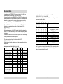
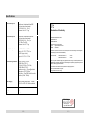
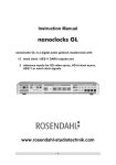
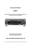
Nanoclocks is a word clock distributor with integrated audio master clock
generator, dual inputs with frequency status indicators and programmable
output matrix – a flexible synchronising tool for all extensive digital audio
installations.
Table of Contents
User Manual
Front Panel
Back Panel
Installation
Distributor Mode
Generator Mode
Failsafe Mode
Specifications
Declaration of Conformity
page
page
page
page
page
page
page
page
Rosendahl Studiotechnik GmbH
80804 Munich
Germany
www.rosendahl-studiotechnik.de
email: [email protected]
interstage
Phistersvej 31, 2900 Hellerup, Danmark
Telefon 3946 0000, fax 3946 0040
www.interstage.dk
- pro audio14
with a smile
-1-
2
4
5
6
8
9
10
11
Front Panel
1. Power Switch
5. Output Source / Output Multiplier LEDs
Turns the power to the Nanoclocks on and off. In FAILSAFE operation mode
the power switch is disabled to prevent switching off by mistake.
See also Chapter Failsafe Mode on page 9.
In operation modes DISTRIBUTOR and FAILSAFE these twelve LEDs indicate the selected source (input A or input B) for each corresponding word
clock output 1-12.
In operation mode GENERATOR the twelve LEDs indicate the selected
output multiplier (Fs x256 for outputs 1-4 and Fs xn for outputs 5-12) for the
corresponding outputs.
2. Operation Mode LEDs
The Nanoclocks has three different operation modes:
6. Setup Keys
DISTRIBUTOR
FAILSAFE
GENERATOR
The three LEDs indicate the selected operation mode. The front panel
silkscreen has two grey lines. The top line (input A status, input B status...)
describes the functions of the LED fields for the two operation modes
DISTRIBUTOR and FAILSAFE.
In the GENERATOR mode the bottom grey line (sample rate, Fs xn....)
is valid.
3. Input A Status / Sample Rate LEDs
Depending on the operation mode of the unit these four LEDs indicate either
the frequency status of input A (DISTRIBUTOR, FAILSAFE mode) or the
selected base sample rate (GENERATOR mode).
4. Input B Status / Fs xn Factor LEDs
Depending on the operation mode of the unit these six LEDs indicate either
the frequency status of input B (DISTRIBUTOR, FAILSAFE mode) or
the selected multiplier Fs xn for outputs 5-12 (GENERATOR mode).
-2-
Pressing the MENU key enters setup mode, the blinking LED indicates the
current selected operation mode. Subsequent depressions of the MENU key
select the parameter to change:
In operation mode DISTRIBUTOR:
Operation mode
Output source 1-12
In operation mode GENERATOR:
Operation mode
Base sample rate
Multiplier Fs xn
Output multipliers 1-12
Depressing the SELECT key cycles through the options for each selected
parameter. Once the desired parameters are set, pressing and holding the
MENU key for approximately one second until the LEDs stop blinking stores
the set up in non volatile memory. For a temporary set-up stay in setup
mode. Turning off the unit when in setup mode and then re-powering the unit
will re-set the previously stored parameters.
-3-
Back Panel
Installation
The Nanoclocks is shipped in two versions:
1.) 230 VAC, 50 Hz
2.) 115 VAC, 60 Hz
Check voltage on the back panel before connecting the unit to mains.
1. Transformer Isolated Inputs A and B
Isolated BNC connectors. Input A and input B are transformer isolated word
clock inputs, internally terminated with 75 ohms.
Input A works with word clock signals from 32 – 100 kHz (Fs x1 – Fs x2) and
input B with signals from 32 – 200 kHz (Fs x1 – Fs x4) or super clock signals
from 10 – 13 MHz (Fs x256).
The optimum solution is to mount the Nanoclocks in the same 19“ rack as
the most important AD/ DA digital audio converters in your studio. These
units should receive the lowest jitter sample clocks. The common grounding
of the 19“ rack will also help improve jitter performance. Comparable to hum
in analog audio lines, modulated ground potentials can create jitter in digital
audio links. For that reason the Nanoclocks has a two pole mains, a linear
power supply and transformer isolated word clock inputs.
2. Word Clock / Super Clock Outputs WO1 – WO4
Note: If you require no more than the twelve word clock outputs provided by
the Nanoclocks feed each digital audio unit with a separate clock line.
BNC connectors, 75 ohms. The first four outputs WO1 - WO4 can be either
DC coupled word clock or AC coupled super clock outputs.
All word clock and super clock cables must be 75 ohm coaxial (RG59).
Do not use 50 ohm coaxial computer network cables (RG58).
3. Word Clock Outputs WO5 – WO12
Most word clock inputs are internally terminated with 75 ohms. You can not
connect two terminated inputs to one word clock output using a BNC-T. Only
if the inputs are switchable or have no termination you can use BNC-Ts to
connect multiple word clock inputs. In this case use very short cables to link
the BNC-Ts. Ensure that only the last input is 75 ohm terminated. Passive
BNC-T links should not be used to link more than 3 inputs. Some word clock
inputs are not internally terminated (Alesis BRC for example). These inputs
must be externally terminated using a BNC-T & 75 ohm terminator.
BNC connectors, 75 ohms. DC coupled word clock outputs.
4. Mains Input
EN 60320, two pole. Use only the supplied AC power cord for the mains
connection.
Check all word clock and super clock signal lines for correct, single-ended 75
ohms termination.
-4-
-5-
Distributor Mode
In operation mode DISTRIBUTOR the two input signals A and B can be
routed individually to each of the 12 word clock outputs.
If your unit is currently in the GENERATOR or FAILSAFE operation mode
please press the MENU key to enter the setup mode. The selected operation
mode LED will start to blink and you can change the operation mode by
pressing the SELECT key until the DISTRIBUTOR LED is blinking.
Press the MENU key once more and the output matrix LED 1 will start to
blink. Now you can select the source for word clock output 1 (WO1):
LED off = input A
LED on = input B
Subsequent depressions of the MENU key step through the output matrix
LEDs 2 to 12 to select individually the source for each corresponding word
clock output.
Press and hold the MENU key for one second (until the LEDs stop blinking)
to store your settings and exit the setup mode.
The status of word clock input A is indicated with four LEDs:
48.000, 44.100, -0.1% and x2.
Table 1 shows all possible combinations with the corresponding word clock
frequencies.
table 1: input A status LEDs, X = LED on, 0 = LED off
input signal
no signal
31.000 Hz - 44.034 Hz
44.035 Hz - 44.078 Hz
44.079 Hz - 44.122 Hz
44.123 Hz - 47.928 Hz
47.929 Hz - 47.976 Hz
47.977 Hz - 48.024 Hz
48.025 Hz - 68.100 Hz
68.100 Hz - 88.068 Hz
88.069 Hz - 88.156 Hz
88.157 Hz - 88.244 Hz
88.245 Hz - 95.856 Hz
95.857 Hz - 95.952 Hz
95.953 Hz - 96.048 Hz
96.049 Hz - 136 kHz
LED
LED
48.000 44.100
0
0
X
X
0
X
0
X
X
X
X
0
X
0
X
X
X
X
0
X
0
X
X
X
X
0
X
0
X
X
-6-
LED
-0.1%
0
0
X
0
0
X
0
0
0
X
0
0
X
0
LED
x2
0
0
0
0
0
0
0
0
X
X
X
X
X
X
X
standard
The status of word clock input B is indicated with six LEDs:
48.000, 44.100, -0.1%, x2, x4 and x256.
Table 2 shows all posible combinations with the corresponding word clock
frequencies in addition to table 1.
table 2: input B status LEDs
LED LED
LED LED
48.00 44.10 -0.1% x2
0
0
X
0
0
X
X
X
0
0
X
X
X
X
X
0
0
X
X
X
0
0
0
X
0
X
0
0
X
0
X
0
0
0
0
0
0
0
0
0
0
0
LED
x4
LED
X256
standard
0
X
X
X
X
X
0
0
0
0
0
0
0
0
0
0
0
X
X
X
X
X
See table 1
non standard Fs > 136 kHz
176,4 kHz pull down
176,4 kHz
192 kHz pull down
192 kHz
non standard F input > 8 MHz
11,2896 MHz pull down
11,2896 MHz
12,288 MHz pull down
12,288 MHz
Note: Only word clock outputs 1-4 can distribute Fs x256 super clock signals.
Outputs 5-12 are automatically switched back to distribute signal A when a
super clock signal is detected on input B.
non standard
44.1 pull down
44.1
non standard
48 pull down
48 kHz
non standard
non standard
88.2 pull down
88.2
non standard
96 pull down
96 kHz
non standard
-7-
Generator Mode
Failsafe Mode
In GENERATOR mode the unit works as an ultra low jitter audio master
clock generator with 12 clock outputs. Please note that in this operation
mode the bottom grey line of the front panel silkscreen is valid.
Operation mode FAILSAFE monitors the two input signals and performs an
automatic switch over of all 12 outputs if the primary (input A) word clock
signal fails.
Supported base sample rates are 44.1 and 48 kHz, outputs 1-4 can be set
individually to output Fs x1 word clock or Fs x256 super clock signals. The
other outputs 5-12 can be configured as Fs x1 (base sample rate) or Fs xn
word clock ; the multiplier Fs xn can be set to x2 (88,2 / 96 kHz) or x4 (176,4/
192 kHz).
Connect the primary word clock reference to input A and the auxiliary word
clock signal to input B.
Press the MENU key to enter the setup mode and select the FAILSAFE
operation mode with the SELECT key. Press and hold the MENU key for one
second (until the LEDs stop blinking) to store this setting and exit the setup
mode.
Press the MENU key to enter the setup mode and select the GENERATOR
operation mode with the SELECT key. If you press the MENU key once more
the currently selected base sample rate LED will start to blink and the value
(44.100/ 48.000) can be changed with the SELECT key.
Press the MENU key once more to set the multiplier Fs xn to value x2 or x4
with the SELECT key.
Fs nx is the multiplier of the base sample rate for the word clock outputs
WO5 - WO12, if activated for the corresponding output (LEDs 1–12).
Twelve subsequent depressions of the MENU key pass you through the
twelve output matrix LEDs 1-12, with which the currently selected LED is
blinking.
Press the SELECT key to set the corresponding output multiplier on or off.
Press and hold the MENU key for one second until the LEDs stop blinking to
store your settings and exit the setup mode.
In operation mode FAILSAFE the POWER switch is disabled to prevent
switching off by mistake (by technically inquisitive visitors for example).
For the same reason the MENU key must be pressed and held for one
second to enter the setup mode.
The two LED rows „input A status“ and „input B status“ indicate the presence
of both input signals (A and B) and the two sample rate frequencies should
be identical of course in this application. All twelve output matrix LEDs are
automatically set off and the word clock outputs WO1-WO12 distribute the
primary input signal A.
If the primary input signal A fails for the period of one audio frame the unit
performs an automatic switch over of all twelve outputs to signal B.
All twelve output matrix LEDs start blinking (long cycle =on, short cycle =off)
to indicate the performed switch over. (One of the internal LED signals can
be used to drive also external alarm functions..)
The unit does not automatically switch back to the primary input A even
when signal A becomes present again.
The user must press the SELECT key to reset the unit to switch back to the
primary input A.
Only if signal B also fails for one audio frame the unit switches automatically
back to signal A. This operation is then indicated with all twelve LEDs
blinking inverse (short cycle= on, long cycle= off)
This monostable alarm function (all LEDs blinking) is a good way to monitor
word clock signals over long time and make sure the signal did not drop for
even one audio sample.
-8-
-9-
Specifications
word clock input A
word clock input B
word clock outputs
internal clock generator
transformer isolated earthfree BNC,
75 ohms internal terminated
32-100 kHz (Fs x1 - Fs x2),
minimum level = 0.7 Vpp
transformer isolated earthfree BNC,
75 ohms internal terminated
32-200 kHz (Fs x1 - Fs x4) or
10-13 Mhz (Fs x256),
minimum level = 0.7 Vpp
12 x BNC, 3.5 Vpp @ 75 ohms
outputs 1-4: FS x1 - FS x4 or
Fs x256 (super clock)
outputs 5-12: FS x1 - FS x4
48 kHz, 96 kHz, 192 kHz,
12.288 MHz (XTAL 1)
44.1 kHz, 88.2 kHz, 176.4 kHz,
11.2896 MHz (XTAL 2)
crystal accuracy +/- 5 ppm @ ambient
temperature 15-30° Celsius
clock jitter < 10 ps RMS within the audio
spectrum (20Hz - 20kHz)
power supply
internal linear power supply, 10 watts,
115 VAC or 230 VAC version available
dimensions
1U-19" 41,5cm W x 4,2cm H x 12,5cm D
weight
2,0 kg
Declaration of Conformity
Rosendahl Studiotechnik GmbH
Isoldenstraße 26
D-80804 München
herewith confirm that the product:
Type:
Digital Audio Clock Server
Model:
Nanoclocks
meets the requirements of the council of the European communities relating to electromagnetic
compatibility (Council Directive 89/336/EEC)
Technical Data:
CENELEC EN 50 081-1
CENELEC EN 50 082-1
1/1992
1/1992
The CE symbol is awarded to high-quality appliances which comply with the European Directive
89/336/EEC or the EMVG (law relating to electromagnetic compatibility of appliances) and which
offer the following significant benefits:
*Simultaneous and interference-free operation of adjoining appliances
*No unpermitted interference signals
*High resistance to electro-smog
interstage
Phistersvej 31, 2900 Hellerup, Danmark
Telefon 3946 0000, fax 3946 0040
www.interstage.dk
- pro audio with a smile
- 10 -
- 11 -