1
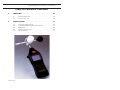
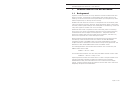
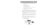
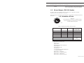
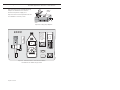
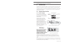
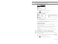
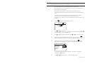
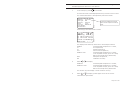
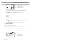
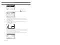
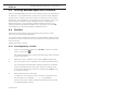
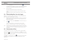
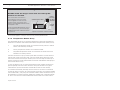
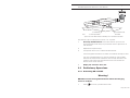
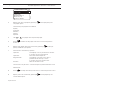
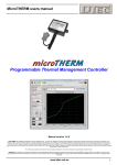
MICROTHERM Heat Stress WBGT &
WinHSM Application Software - User Manual
February 2003
MICROTHERM
Heat Stress WBGT
And WinHSM
Application Software
User Manual
HB3279-04
COPYRIGHT
The copyright in this document which contains proprietary information is vested in
CASELLA CEL. The contents of this document must not be used for purposes other
than that for which it has been supplied or reproduced or disclosed wholly or in part
without the prior written permission of
CASELLA CEL.
CASELLA CEL
Regent House
Wolseley Road
Kempston
Bedford
MK42 7JY United Kingdom
Phone:
+44 (0) 1234 844 100
Fax:
+44 (0) 1234 841 490
E-mail
[email protected]
Web:
www.casellacel.com
CASELLA USA
17 Old Nashua Road #15
Amherst
NH 03031
U.S.A.
Toll Free: +1 800 366 2966
Fax:
+1 603 672 8053
E-mail
[email protected]
Web:
www.casellaUSA.com
MICROTHERM Heat Stress WBGT &
WinHSM Application Software - User Manual
Page 2 of 44
MICROTHERM Heat Stress WBGT &
WinHSM Application Software - User Manual
Warnings
WARNINGS !
Any attempt to charge non-rechargeable cells is
hazardous and can result in damage.
This instrument incorporates an internal fast-charger
circuit suitable for recharging NiMH cells. The charger is
enabled/disabled via a switch in the battery compartment.
(See Figure 9 in Section 2.1.1.)
This instrument is delivered with re-chargeable nickelcadmium cells and with the CHARGER circuit ENABLED.
DISABLE the charger circuit before fitting and using
non-rechargeable cells.
DISPOSAL OF NiMH BATTERIES
Rechargeable batteries contain NiMH and
must be disposed of in a safe manner. In
some countries, this may involve specialist
licensed waste disposal companies.
Used batteries MUST NEVER be disposed of
by placing in a fire or incinerator, nor must
they be punctured, crushed or otherwise
mutilated or opened up in anyway.
NiMH
MICROTHERM instruments contain no user serviceable
components. If an electrical fault is suspected the
instrument must be returned to Casella CEL Ltd for repair.
The instrument and sensors contain delicate components.
They should not be dropped or subjected to mechanical
shock. Failure to comply will render the warranty invalid.
Page 3 of 44
MICROTHERM Heat Stress WBGT &
WinHSM Application Software - User Manual
Getting Started
GETTING STARTED
It is suggested that you prepare and operate your
Microtherm following the sequence of sections in the
Operations Chapter:
Preparation,
Measurement,
Logging.
Page 4 of 44
MICROTHERM Heat Stress WBGT &
WinHSM Application Software - User Manual
Contents
TABLE OF CONTENTS
1.
DESCRIPTION OF THE MICROTHERM . . . . . . . . . . 7
1.1
1.2
1.3
1.4
1.5
1.6
2.
OPERATION . . . . . . . . . . . . . . . . . . . . . . 13
2.1
2.1.1
2.1.2
2.2
2.2.1
2.2.2
2.2.3
2.3
2.4
2.5
2.5.1
2.5.2
2.5.3
3.
Background . . . . . . . . . . . . . . . . . . . . . . . . 7
Description . . . . . . . . . . . . . . . . . . . . . . . . . 8
The Sensor Array. . . . . . . . . . . . . . . . . . . . . . 9
The Microtherm Menu Structure . . . . . . . . . . . . . 10
Alarm Output / RS 232 Socket . . . . . . . . . . . . . . 11
Schedule of Parts . . . . . . . . . . . . . . . . . . . . . 11
Preparation for Use . . . . . . . . . . . . .
Power Supply . . . . . . . . . . . . . . . . .
Temperature Sensor Array . . . . . . . . . .
Preliminary Operations . . . . . . . . . . . .
Switching ON and OFF . . . . . . . . . . .
Checking Battery Status & Firmware Version
Configuring for the Current Measurement . .
Calibration . . . . . . . . . . . . . . . . . .
Measurement. . . . . . . . . . . . . . . . .
Data Logging . . . . . . . . . . . . . . . . .
Configuring the Logger . . . . . . . . . . . .
Clearing the Logger Memory . . . . . . . . .
Start Logging . . . . . . . . . . . . . . . . .
.
.
.
.
.
.
.
.
.
.
.
.
.
.
.
.
.
.
.
.
.
.
.
.
.
.
.
.
.
.
.
.
.
.
.
.
.
.
.
.
.
.
.
.
.
.
.
.
.
.
.
.
.
.
.
.
.
.
.
.
.
.
.
.
.
.
.
.
.
.
.
.
.
.
.
.
.
.
13
13
14
15
15
16
17
20
20
22
22
23
23
WinHSM APPLICATION SOFTWARE . . . . . . . . . . 27
3.1
3.2
3.3
3.3.1
3.3.2
3.4
3.5
3.5.1
3.5.2
3.5.3
3.5.4
3.6
Installation on Windows 95™, 98™ & Windows NT™ .
Starting WinHSM Application Software . . . . . . . .
Profiles . . . . . . . . . . . . . . . . . . . . . . . . .
Creating/Editing a Profile . . . . . . . . . . . . . . . .
Sending a Profile to the Instrument . . . . . . . . . .
Downloading Data from the Logger . . . . . . . . . .
Presentation of Data . . . . . . . . . . . . . . . . . .
Displaying the Data Summary . . . . . . . . . . . . .
Displaying Data as a Table . . . . . . . . . . . . . . .
Displaying Data as a Graph . . . . . . . . . . . . . . .
Exporting Data to Other Applications . . . . . . . . . .
Real-Time Display Mode . . . . . . . . . . . . . . . .
.
.
.
.
.
.
.
.
.
.
.
.
27
28
28
28
29
30
30
30
34
35
35
36
Page 5 of 44
Contents
MICROTHERM Heat Stress WBGT &
WinHSM Application Software - User Manual
TABLE OF CONTENTS (Continued)
4.
SERVICING . . . . . . . . . . . . . . . . . . . . . . . 39
4.1
4.2
5.
Service Department . . . . . . . . . . . . . . . . . . . 39
Fault Finding Tips . . . . . . . . . . . . . . . . . . . . 39
SPECIFICATION . . . . . . . . . . . . . . . . . . . . 41
5.1
5.2
5.3
5.4
5.5
Page 6 of 44
Instrument Specification . . . . . . . . .
WinHSM PC Based Application Software
Spare Parts . . . . . . . . . . . . . . . .
Optional Accessories . . . . . . . . . . .
CE Compliance . . . . . . . . . . . . . .
.
.
.
.
.
.
.
.
.
.
.
.
.
.
.
.
.
.
.
.
.
.
.
.
.
.
.
.
.
.
.
.
.
.
.
.
.
.
.
.
41
43
43
44
44
MICROTHERM Heat Stress WBGT &
WinHSM Application Software - User Manual
Description
1.
DESCRIPTION OF THE MICROTHERM
1.1
Background
A person’s thermal comfort is mainly related to the thermal balance of their
body as a whole. This balance is influenced by their physical activity and
clothing, as well as the environmental parameters of, air temperature, mean
radiant temperature, air velocity and air humidity.
Problems of heat stress are common in workplaces such as foundries, steel
mills, brick glass and ceramic factories, power generation plants, coke ovens,
laundries, modern glass buildings with inadequate air conditioning, mines and
many other types of outdoor work in hot climates.
Whenever heat stress is imposed on the human body, there is a resulting
strain which may result in physiological reactions such as sweat production,
increased heart rate and higher core temperature. The greater the heat
stress, the greater heat strain and under certain conditions, the latter may
attain such magnitude as to cause damage to health.
Several indices have been designed to integrate the environmental factors
contributing to heat stress and one such index is the Wet Bulb Globe
Temperature Index. The WBGT index was initially developed to provide a
simple method for assessment of heat stress among military personnel. The
Microtherm Heat Stress WBGT determines two WBGT values.
For inside applications and outside measurements with no solar load, the
WBGT inside value is used.
WBGTin = 0.7tnw + 0.3ta
For outside measurements with solar load, the WBGT outside value is used.
WBGTout = 0.7tnw + 0.2tg + 0.1ta
Higher exposures to heat than those shown in Table 1 are permissible if the
workers have been undergoing medical surveillance and it has been
established that they are more tolerant to work in heat than the average
worker. Workers should not be permitted to continue their work when their
deep body temperature exceeds 38 oC.
Page 7 of 44
MICROTHERM Heat Stress WBGT &
WinHSM Application Software - User Manual
Description
Table 1: Permissible Heat Exposure Threshold Limit Values
(values are given in oC WBGT)
Work Regimen
Work Load
Light
Moderate
Heavy
Continuous Work
30.0
27.7
25.0
75% Work
25% Rest, Each Hour
30.6
28.0
25.9
50% Work
50% Rest, Each Hour
31.4
29.4
27.9
25% Work
75% Rest, Each Hour
32.2
31.1
30.0
1.2
Description
The Casella Microtherm Heat Stress Wet Bulb Globe Temperature (WBGT)
monitor is shown in Figure 1.
Sensor array
Globe temperature
sensor
Radiation shield
with dry sensor
inside
Water reservoir
Wet temperature
sensor
Knurled
locking ring
Cotton wick
Control unit
Escape
ON / OFF
Battery charging
indicator
00061
MICROTHERM
Navigator keys
Heat Stress WBGT
Enter
Figure 1: General layout of the Microtherm Heat Stress WBGT
Page 8 of 44
MICROTHERM Heat Stress WBGT &
WinHSM Application Software - User Manual
Description
It is a compact, site monitoring instrument intended primarily for tripod
mounting but may also be handheld; it has the following main features.
¤ LCD graphics display
¤ Real-time display
¤ Full datalogging facilities as standard
¤ Low water level warning
¤ Built-in alarm for WBGT levels
¤ RH% and dewpoint calculation
¤ Automatic calculation of work / rest regimes via PC Software
¤ Optional tripod mounting and extension cable
¤ Meets the requirements of ISO 7234/ DIN
¤ Ergonomic design
The sensor array can be mounted directly on the instrument case, or
detached and mounted on a tripod with an extension cable to provide remote
sensing. Accuracy is achieved by using Platinum Resistance Temperature
Detectors manufactured to high standards of accuracy, stability, and
sensitivity. These sensors conform to the requirements of IEC 751 class A
and EN 60751 class A. On the sensor array, a radiation shield is provided for
the dry temperature sensor.
The instrument will operate from rechargeable batteries, primary cells, or
mains power supply while the high definition liquid crystal display is capable
of showing both text and graphical information. It also shows instrument
configuration details, temperature levels, logger information and battery
condition.
The instrument uses a membrane keypad for all control functions, while a
serial (RS 232) socket is provided for data transfer to a PC for data
manipulation and presentation using Casella WinHSM application software.
1.3
The Sensor Array
Fill Level
Wet Temperature
Air Temperature
Globe
Temperature
Tripod Bush
00062
Connector
Figure 2: The Sensor Array
Page 9
Description
MICROTHERM Heat Stress WBGT &
WinHSM Application Software - User Manual
The sensor array is illustrated in Figure 2. It consists of three platinum
resistance temperature detectors (PRTD) to measure three ambient
temperatures as follows.
Wet Temperature Sensor
Mounted vertically with a tubular cotton wick over its length and the end of
the cotton extending into a water reservoir. (Always use distilled water.)
Dry Temperature Sensor
Oriented at 90o from the wet temperature sensor and fitted with a radiation
shield.
Globe Temperature Sensor
A sensor within a black globe monitors temperature increase due to incident
heat radiation.
The complete sensor array can be removed from the control unit and
mounted on a tripod for remote operation via extension leads up to 50 m
long.
1.4
The Microtherm Menu Structure
The operator interface is based upon a series of menu options organised as
shown on the fold-out sheet at the back of this book.
A combination of function keys and navigator keys on the front panel of the
instrument are used to move around the menu system and change setup
parameters.
Their functions are as follows.
and
and
Enter
Esc
Navigator keys used to move around the
current menu options.
Navigator keys used to change the
contents of the selected field, such as
the indicated date, time, logging interval,
etc.
Enter key that accepts the current menu
option or highlighted option.
Esc (Escape) key that steps back to a
previous menu.
Press this key several times at any point
to obtain a short cut back to the Main
menu.
The Main menu contains all parameters and options relevant to operation and
gives access to the two sub-menus.
Configuration menu
Page 10 of 44
Allows the instrument parameters to be
specified.
MICROTHERM Heat Stress WBGT &
WinHSM Application Software - User Manual
Logger
1.5
Description
Allows the logger to be configured and
data storage to be started and stopped.
Alarm Output / RS 232 Socket
An alarm output is available which switches from a logic 0 to 5 V DC
whenever the on-screen alarm is active.
Figure 3 shows line usage in the connector, while Table 2 identifies the line
functions.
1.6 Schedule of Parts
Figure 3:
Line identities of the Alarm / RS 232 socket,
viewed externally (i.e. also from the solder
bucket side of the plug)
5
6
3
4
2
1
00018
Table 2: RS 232 Connector line functions
Function
Pin Number Wire Colour
9-way D Type
(PC RS 232)
Ground
1
Yellow
Alarm
2
Red
N/A
N/A
RS 232 Receive in
3
White
3 (TX out)
RS 232 Transmit out
4
Black
2 (RX in)
Comms ground
5
Blue
5 (Ground)
4 (DTR), 8 (CTS), 6
(DSR)
Linked together
Microtherm Control Unit
Sensor Array
Carry Case
RS 232 Lead and PC Software
Water Bottle
Wicks (pack of 10)
User Manual
4 x NiCad Rechargeable Batteries
12 V power supply
Mains Plug - UK Fitting
Mains Plug - European Fitting
Mains Plug - USA Fitting
Mains Plug - Australian Fitting.
Page 11 of 44
Description
MICROTHERM Heat Stress WBGT &
WinHSM Application Software - User Manual
Figure 4 shows how the relevant plug
adaptor for different local areas is
fitted to the power supply unit.
Slide to
Unlock
Figure 5 shows the components of the
kit installed in the carry case.
02055
Figure 4: Fitting plug adaptor
00064
Insert Water
Bottle this
way round
to prevent
leakage if
the cap is
not screwed
on tightly.
Figure 5: The Microtherm Heat Stress WBGT
installed in the fitted carying case
Page 12 of 44
MICROTHERM Heat Stress WBGT &
WinHSM Application Software - User Manual
2.
Operation
OPERATION
The Microtherm Heat Stress WBGT is a sensitive scientific instrument which
should not be exposed to excessive moisture, vibration, or physical shocks.
The following steps must be performed before your Microtherm can be used
under operating conditions. It is suggested that you follow the sequence of
sections in this chapter.
2.1
Preparation for Use
Infrared Interface
2.1.1 Power Supply
The Microtherm is powered by
four AA size batteries located in a
compartment in the underside of
the instrument.
The instrument can also be
powered continuously using
external power applied via the
12 V DC socket (Figure 6),
without the need for internal
batteries to be installed. To gain
access to the batteries, lift the
bottom end of the cover slightly
to release it, then slide
downwards in the direction of the
arrow mark (Figure 7).
12 V DC
Power
RS 232
Tripod Bush
00058
Figure 6: Bottom panel connectors
Lift End
to
Release
Cover
Slide Off
00021
Figure 7: Removing battery cover
Warning !
One cell installed with the
wrong polarity may still
allow operation, but can
cause overheating severe
enough to rupture a cell and
damage the instrument.
00015
Figure 8: Loading batteries
Load four new batteries (AA or equivalent) in the orientations shown in
Figure 8. Rechargeable nickel-cadmium (NiCd) 1.2 V batteries are recommended. 1.5 volt alkaline and other non-rechargeable batteries can also be
used.
Rechargeable batteries may be supplied by Casella CEL in a discharged state.
In order to obtain maximum capacity from new NiCd batteries, several charge
and discharge cycles may be required.
Page 13 of 44
Operation
MICROTHERM Heat Stress WBGT &
WinHSM Application Software - User Manual
Warning !
DO NOT enable the charger circuit while non-rechargeable
batteries are installed.
ON
2
When rechargeable batteries are to
be charged in situ, set the Charger
Enable DIP switch to ON as shown
in Figure 9.
Serial Number Label
1
The instrument has a built in
fast-charging circuit that uses
power applied via the 12 V DC
socket shown in Figure 6. This
allows rechargeable batteries to be
recharged in-situ.
Factory
use only.
DO NOT
ADJUST
Charger
Enable
00060
Figure 9: Location of DIP switches
Charging will terminate automatically once the batteries are fully charged,
which takes approxi- mately 3 hours for fully discharged batteries.
2.1.2 Temperature Sensor Array
The detachable sensor array houses three platinum resistance temperature
detectors to measure three associated ambient temperatures (see Figure 2).
1.
The wet temperature sensor is mounted vertically and has a tubular
cotton wick sheathing its length.
2.
The dry temperature sensor has a radiation shield.
3.
The globe temperature sensor is mounted at the other end of the
crossbar from the dry sensor.
Connect the sensor array by inserting the cable connector into the socket in
the top end of the instrument case, with the red dot facing the front of the
instrument to ensure correct pin location, then turn the large knurled ring to
tighten the security collet. (Remember to free the collet before attempting to
remove the sensor array.)
In use, the sensor array must be maintained with the crossbar horizontal to
prevent spillage from the water container during the duration of a typical
measurement (which should take at least 20 minutes on each station).
This is best achieved by standing the instrument on its foot on a horizontal
surface as shown in Figure 10, mounting the instrument on a tripod (available
from Casella CEL), or by using an extension cable to allow the sensor array to
be installed on a tripod. Extension cables are available with a standard length
of 10 m. The maximum distance between sensors and instrument is 50 m.
Page 14 of 44
MICROTHERM Heat Stress WBGT &
WinHSM Application Software - User Manual
00063
1/4" Whitworth/
1/4" UNC Tripod Bush
Operation
Foot Permanently
Attached
Figure 10: The Microtherm standing on a horizontal surface
The reservoir cap is a tight push fit with an “O” ring seal.
1.
Use only distilled water and fill the reservoir up to the line
engraved inside. Over filling may cause the water to siphon out of
the container.
2.
Replace the cap after filling.
3.
Change the cotton wick if it becomes discoloured.
Use the supplied screwdriver to tease out the fibres enough to allow
the wick to be pulled down to the first shoulder on the wet bulb.
Also use the screwdriver to ease the wick through the hole in the
reservoir cap. Check that the free end of the wick reaches the
bottom of the water reservoir.
4.
Empty the reservoir after use.
2.2
Preliminary Operations
2.2.1 Switching ON and OFF
Warning !
DO NOT use non-rechargeable batteries while the charging
circuit is enabled.
1.
Press
to switch your Microtherm ON.
Page 15 of 44
MICROTHERM Heat Stress WBGT &
WinHSM Application Software - User Manual
Operation
A welcome screen will be displayed showing the instrument’s name.
Whenever the internal charger circuit has been enabled as described
in Section 2.1.1 and Figure 9, and external power is applied, i.e. the
charger is actually charging the internal batteries, the following
warning screen is displayed suggesting that the batteries be
checked to make sure they are rechargeable.
WARNING
MTH01
Battery Charger ON
C h e c k N i C a d Ty p e
Batteries Fitted
Esc
The next screen shows information about the instrument, such as
battery condition, charger switch setting, memory capacity and the
installed firmware (internal software) version.
The charger switch will be shown OFF when no external power is
present.
Finally a measurement screen is displayed.
in / out
24.2
MTH02
WBGT
oc
IN
Ta =2 4 . Ø o c D e w =2 3 . 7 o c
Tg =2 3 . 8 o c R H =9 8 . 3 %
T n w =2 2 . 1 o c WATER LOW
WBGTin TWA
= - - - .- o c
When switched ON the readings may drift a small amount, so allow
at least one minute for the instrument to settle.
2.
Press
to switch your Microtherm OFF.
2.2.2 Checking Battery Status & Firmware Version
The internal battery voltage is displayed on a Status screen, together with the
instrument firmware (internal program) version.
1.
Switch the instrument ON and wait for the measurement screen to
be displayed, as described in Section 2.2.
2.
Press
Page 16 of 44
Esc
to display the Main menu.
MICROTHERM Heat Stress WBGT &
WinHSM Application Software - User Manual
3.
Use
4.
Press
or
Enter
MTH04
MAIN MENU
View Graph
View Measurement
Status
Logger
Configuration
Operation
to highlight the Status option.
to display the Status screen.
Ø1/ Dec/ ØØ 1Ø:25:55
Ignore the displayed voltage
when external power is being
used.
MTH05
Battery
4.9 volts
Charger Off
Memory
2% Full
Runs
1/32
Ve r s i o n
NN-NN-N
User Name
and Details
When the indicated voltage is greater than 4.8 V, the batteries are in
a fully charged condition.
If the voltage from rechargeable batteries is lower than 4.2 V, more
than 80% of the capacity has been used.
Consider Recharging !
The battery icon will blink to warn that the internal battery is
approaching discharge.
Then when the batteries become discharged, logging is terminated
and the instrument will commence an automatic shut down
sequence.
The battery voltage will be shown as 10 V while external power is
being applied.
2.2.3 Configuring for the Current Measurement
The Configuration menu enables all functions for the instrument’s current
operating mode to be defined.
1.
With the Main menu on display (see Section 2.2.2), use
highlight the Configuration option.
2.
Press
Enter
or
to
to display the Configuration menu.
Page 17 of 44
C O N F I G U R AT I O N
Back Light
Time & Date
Language
Serial Comm's
Units oC / oF
Buzzer / Alarm
3.
MTH12
MICROTHERM Heat Stress WBGT &
WinHSM Application Software - User Manual
Operation
Specify the user language by pressing
Language option.
Enter
while highlighting the
The following languages are available:
English,
Française,
Deutsch,
Italiano,
Español.
4.
Use
or
to highlight the required language.
5.
Press Enter to select the language and return to the Configuration
screen.
6.
Specify the display back light function by pressing
lighting the Back Light option.
7.
Choose from the following options:
Light ON
Light OFF
Keypress ON
Duration
Enter
while high-
The display is lit as you leave this screen.
It remains lit until switched off.
Switches the backlight off.
The display is lit each time a key is
pressed while viewing a menu.
It remains lit for the duration set.
Sets the duration timer.
The duration may be set in 1 second steps anywhere between 5 and
30 seconds.
Enter
8.
Press
9.
Specify the time and date by pressing
Time & Date option.
Page 18 of 44
to accept the setting and return to the Configuration menu.
Enter
while highlighting the
MICROTHERM Heat Stress WBGT &
WinHSM Application Software - User Manual
Operation
The only option on the Time & Date screen is Set Clock.
The instrument has an internal real-time clock, which should be set
to the current time and date.
When data is being logged, the measured temperatures and
calculated parameters will be recorded against the current date and
time.
However, when the instrument is configured by the WinHSM
software, the time and date on the internal clock are set
automatically to the PC’s time and date. Please refer to Chapter 3 for
details.
10.
Press
Enter
to display the Set Clock screen.
Set Clock
MTH19
Fri Ø1 / Dec / 2ØØØ
14: 59: 26
11.
Use
or
to select a time or date field to be edited and
to edit the entry in the selected field.
12.
Use
13.
When all entries on the Set Clock screen are correct, press
accept the settings and return to the Time & Date screen.
14.
Specify the serial communication details by pressing Enter while
highlighting the Serial Comm’s option on the Configuration menu.
or
to select other fields and
or
or
to edit the entries.
Enter
to
Baud Rate
Data Bits
Stop Bits
Parity
:
:
:
:
96ØØ
8
1
None
MTH16
Serial Comms
The Serial Comms screen is displayed, where the only setable
parameter is Baud Rate.
15.
Use
or
to edit the entry in the Baud Rate field.
Page 19 of 44
MICROTHERM Heat Stress WBGT &
WinHSM Application Software - User Manual
Operation
16.
When the entry matches the requirements of your PC (also see
Section 3.3.1), press
17.
Enter
to accept the setting.
Specify whether the measurement units should be oC or oF by
pressing Enter while highlighting the Units oC / oF option on the
Configuration menu.
18.
Use
or
19.
Press
20.
Specify alarm requirements by pressing Enter while highlighting the
Buzzer / Alarm option on the Configuration menu.
Enter
to select the required units.
to accept the setting.
The Buzzer / Alarm screen is displayed.
Buzzer
Alarm
Threshold
21.
Disable
WBGT
3Ø,ØoC
(86,ØoF)
MTH18
Buzzer / Alarm
Choose from the following options:
Buzzer
Alarm
Threshold
Disable, Enable
WBGT, WBGTtwa, Disable, Ta,
0.0 to 40.0 oC in 0.1o steps.
As the majority of heat stress legislation is written in terms of oC,
threshold alarm settings can be specified only in increments of oC.
However, the equivalent oF value is also shown.
22.
Press Enter to accept the settings and return to the Configuration
menu.
2.3
Calibration
The sensors are manufactured to high standards of accuracy, stability, and
sensitivity so that separate calibration is not normally required.
2.4
Measurement
For most consistent measurement, stay at least 20 minutes on each station.
Page 20 of 44
MICROTHERM Heat Stress WBGT &
WinHSM Application Software - User Manual
1.
If not already on, press
Operation
to swith ON.
A welcome screen will be displayed showing the instrument’s name.
This will be followed for a brief period by the status screen.
Ø1/ Dec/ ØØ 1Ø:25:55
Battery
4.9 volts
Charger Off
Memory
2% Full
Runs
1/32
Ve r s i o n
NN-NN-N
User Name
and Details
MTH05
Ignore the displayed voltage
when external power is being
used.
And finally by the measurement screen.
in / out
=2 4 . Ø o c
24.2
oc
Ta
D e w =2 3 . 7 o c
o
Tg =2 3 . 8 c R H =9 8 . 3 %
T n w =2 2 . 1 o c WATER LOW
WBGTin TWA
= - - - .- o c
MTH02
WBGT I N
This displays the following measured or calculated parameters:
WBGTin
Ta
Tg
Tnw
WBGTin TWA
Wet bulb globe temperature - indoors,
Air temperature,
Globe temperature,
Natural wet temperature,
Wet bulb globe temperature - indoors:
time weighted average, given as a rolling
60 minute average every 30 seconds,
Dewpoint temperature,
%Relative humidity.
Dew
RH
2.
Press
or
WBGTout
WBGTout TWA
to display:
Wet bulb globe temperature - outdoor,
Wet bulb globe temperature - outdoor:
time weighted average, given as a rolling
60 minute average every 30 seconds.
This screen may also display a water condition warning.
3.
Press
or
to display a profile graph of one of the current
measurement parameters.
Page 21 of 44
MICROTHERM Heat Stress WBGT &
WinHSM Application Software - User Manual
Operation
30
Battery icon that empties as
power is drained
oc
Ta = 2 4 . Ø o c
15 min
MTH03
Current parameter value
20
This graph scrolls across the screen from right to left as samples are
collected, with the current parameter and value identified.
4.
Press
to change the displayed parameter on the graph.
The options are:
Ta,
WBGT out,
WBGT in,
Dewpoint,
Relative Humidity,
Tg,
Tnw.
5.
Press
to change the time base between: 15, 30, 60, 120 minutes.
6.
Press
or
2.5
Data Logging
again to return to the measurement display.
2.5.1 Configuring the Logger
Before storing data, the logger should be configured for the proposed
measurements.
1.
Display the Logger screen by selecting the Logger option from the
Main Menu.
2.
From the Logger screen, select and display the Config Logger
screen.
Intervals:
1 Min
Log Time: Ø34,Ø3:12:ØØ
Mode: Stop When full
Clear Memory: No
3.
Select logger Intervals.
Page 22 of 44
MTH10
Config Logger
Logging time available
(depends upon the intervals
set and the amount of free
memory space).
The time is shown as:
“ddd,hh:mm:ss”
MICROTHERM Heat Stress WBGT &
WinHSM Application Software - User Manual
Operation
The logger interval is the time between each recorded data point
The following options are available:
30 seconds,
1, 2, 3, 4, 5, 6, 10, 15, 20, 30, 60 minutes.
4.
If necessary, change the current setting.
5.
Select logger Mode.
The logger mode determines what happens when all empty memory
locations have been filled with data.
6.
If necessary, change the setting to one of the following alternatives:
Over Write Run
Stop When Full
The logger simply carries on recording
data so that the oldest records will be
overwritten by new ones.
The logger stops logging when the
memory is full.
2.5.2 Clearing the Logger Memory
The Microtherm has a logging capacity of over 40 000 intervals (giving more
than 245 000 individual temperature or relative humidity results) and 32 runs,
with the total number of stored runs shown on the Status screen.
When there is insufficient space remaining in the instrument store for the
projected logging run, stored data can be deleted. All recorded data should
be downloaded before clearing the logger’s memory as there are no facilities
to recover data deleted from the instrument.
1.
Select and display the Config Logger screen (see Section 2.5.1).
2.
Highlight the Clear Memory option, select YES then press
Enter
.
A warning message will be displayed asking for confirmation before
the contents of the memory are erased.
3.
Press
Enter
to confirm the erase operation.
ALL stored runs will be DELETED.
2.5.3 Start Logging
1.
With the logger settings configured as described in Section 2.5.1,
(and the memory cleared when necessary) display the Logger
screen.
Page 23 of 44
MICROTHERM Heat Stress WBGT &
WinHSM Application Software - User Manual
Operation
Logger
Start Logger
View Runs
Config Logger
Highlight the Start Logger option and press
2/3
Enter
to start logging.
Ø5:32
WBGT I N
=2 4 . Ø o c
24.2
oc
Ta
D e w =2 3 . 7 o c
o
Tg =2 3 . 8 c R H =9 8 . 3 %
T n w =2 2 . 1 o c WATER LOW
WBGTin TWA
= - - - .- o c
MTH08
2.
2% Full
1 / 32
MTH06
Memory
Runs
The measurement screen displays levels from the current interval.
3.
Press
and
to switch between displays with WBGT indoor and
WBGT outdoor values.
4.
Press
and
to switch between the measurement screen and a
graph of one of the parameters.
2/3 Ø5:32
30
20
Ta = 2 4 . Ø o c
15 min
MTH07
oc
Both screens identify the run and show the current interval number.
Data stored during the current (or other runs) can be reviewed on the
instrument display while it is being collected.
From the Logger screen, select and display the View Runs screen.
Run Number:Ø1/Ø2
Date: Fri Ø1/Dec/ØØ
Start:
16:1Ø:57
Duration: Ø1:29:44Ø
Maxoc Minoc
W B G T:
i n T W A = : - - - .- - - - .o u t T W A = : - - - .- - - - .Page 24 of 44
MTH09
5.
MICROTHERM Heat Stress WBGT &
WinHSM Application Software - User Manual
Operation
A summary screen for the most recent stored run will be displayed.
6.
Use
or
to select summaries from other runs.
The run number and total of runs will be indicated; the current run
will also be available.
Use
or
to display a data screen for the run.
Run Number:Ø1/Ø2
Maxoc Minoc Aveoc
Ta =2 5 . 6 2 5 . 5 2 5 . 6
Tg =2 5 . 7 2 5 . 7 2 5 . 7
T n w =2 5 . 5 2 5 . 5 2 5 . 5
WBGT in =
25.6
WBGT out =
25.6
MTH11
7.
Maximum, minimum and average values for the whole run are
shown.
8.
When sufficient data has been collected, stop logging by returning to
the Logger screen and using the Stop Logger option.
Logging stops and data up to the last completed interval is saved.
At the end of each logging run (i.e. when logging is stopped or the
instrument switched off) a summary record will also be saved.
Each summary record contains the maximum, minimum and average
values for the whole run, together with the start date and time plus
the run duration.
Page 25 of 44
Operation
MICROTHERM Heat Stress WBGT &
WinHSM Application Software - User Manual
Stored data can be downloaded for further manipulation and
reporting
only by using WinHSM Application Software.
Page 26 of 44
MICROTHERM Heat Stress WBGT &
WinHSM Application Software - User Manual
3.
Application
Software
WinHSM APPLICATION SOFTWARE
WinHSM Application Software supports the data logger facilities offered by
the Microtherm Heat Stress WBGT. It is specifically written by Casella CEL to
simplify the process of instrument configuration, downloading and data
presentation.
The application, supplied on three 1.44 MB 3 1/2“ floppy disks, is designed to
operate within the 32 bit environment of Windows 95 and later or Windows
NT 4 and later.
The instrument communicates with the PC using an RS 232 serial port.
3.1
Installation on Windows 95™, 98™, ME™,
Windows NT™ & Windows 2000™
System Requirements:
IBMTM compatible PC with Pentium II or better processor ,
At least 16 MB of free RAM space,
Microsoft Windows 95/98, Windows NT,
Hard drive with at least 4 MB of free space,
RS 232 Serial Communication Port,
31/2“ high density (1.44 MB) floppy disk drive for program
installation,
Super VGA colour monitor,
Printer - optional.
Before installation, it is recommended that a back-up copy be made of the
program disks. Keep the originals in a safe place and use the copy to install
the software. The Setup program for WinHSM will install files in the specified
Program directory and also in the Windows\System directory.
1.
Start Windows.
2.
Insert WinHSM Disk 1 into the floppy disk drive.
3.
Select Start from the task bar, then Run…
4.
Type a:\setup, where “a” identifies the floppy disk drive, then press
Enter.
5.
Wait for the Casella CEL welcome screen to be displayed, then
follow the on-screen instructions.
Once installation is complete, a WinHSM icon will
be found on your Windows desktop.
Page 27 of 44
Application
Software
3.2
MICROTHERM Heat Stress WBGT &
WinHSM Application Software - User Manual
Starting WinHSM Application Software
Start the WinHSM application software by double clicking on its desktop icon,
or selecting it from the Start Menu. The top level window will be displayed.
As the cursor is moved to each menu button, the relevant function will be
displayed on the message line at the bottom left of the display. If this is the
first time that you open the newly installed software, a dialog will be
displayed telling you that no profile has been defined and asking you to
create and select one before proceeding. Your only option is to click OK,
which displays the Active Profile dialog, (see Section 3.3.1).
3.3
Profiles
Profiles are used to identify the unique operating parameters of each
instrument or measurement application.
In situations where multiple instruments are interrogated by one PC, the use
of profiles provides a convenient way of identifying and managing data from
each instrument.
Profiles are stored in the PC.
3.3.1 Creating/Editing a Profile
1.
Create a new profile by selecting the Profiles... option on the Edit
menu, or by clicking
.
You will be presented with the Active Profile dialog where the active
profile is highlighted.
2.
Select the name of a profile to edit or press New as appropriate.
3.
For a new profile, enter a suitable name in the Profile Name dialog.
Four tab Properties dialogs define the basic features of the profile.
The ID dialog specifies the instrument identity and selects a predrawn 128 wide by 64 high, black and white bitmap ( .bmp) for use
as a welcome screen
4.
Make suitable entries in the fields.
In addition to normal alpha-numeric characters, the following may
also be used in the messages, “ + - : ( ) + - # and SPACE”.
The Communications dialog configures the RS 232 serial interface
and specifies Modem details.
Page 28 of 44
MICROTHERM Heat Stress WBGT &
WinHSM Application Software - User Manual
Application
Software
The Port, Baud Rate and a modem Telephone Number may need to
be defined.
5.
Make entries in the Comms fields to suit the PC and
communications
port in use.
If a mouse or some other device is already installed on Com1, then
change the entry to another free port.
Also make sure that both PC and Microtherm instrument are set to
the same baud rate.
The Data Files dialog specifies a file prefix and store location for the
data files to be downloaded.
As the instrument may contain data from many different sampling
runs, the downloaded data will be split into individual files, each one
representing a single run.
The File Prefix defines the first part of the file name for downloaded
data. You may want to add a hyphen (as shown below), to separate
the date from the prefix.
The file name will be of the form:
fileprefix-yyyy-mm-dd,hh;mm;ss.hsm
(for example: Site1-2001-02-20,20:14:06.hsm) Where the date and
time part of the file name refer to when the run was started.
6.
Make a suitable entry.
7.
When the default directory is not suitable, use the Browse option to
select a file path and directory for storing data files.
The Units dialog specifies whether the temperatures displayed by
the PC will be defined in oC or oF.
8.
Make a suitable choice.
9.
Press OK to save the information in the profile.
10.
Press Accept to accept this as the active profile.
3.3.2 Sending a Profile to the Instrument
The configuration information contained in an instrument profile must be
transferred to the Microtherm. Before attempting to send a profile, make
sure the instrument is switched on and the serial communications cable
plugged into both the instrument and the appropriate port on your PC.
Page 29 of 44
MICROTHERM Heat Stress WBGT &
WinHSM Application Software - User Manual
Application
Software
1.
Select Send Profile from the Comms menu, or click
.
A message will be displayed, warning that this procedure will erase
all data in the instrument and asking if you want to continue.
2.
Start the transfer.
Any errors will be reported and the transfer aborted.
During the transfer, the instrument’s internal clock will be reset
using
the date and time from the PC. (Ensure the PC’s clock is correctly
set !)
3.4
Downloading Data from the Logger
Before you can generate graphs and tables from the data recorded by the
Microtherm, you must download it to your PC.
1.
Make sure the instrument is switched on and the communications
cable plugged into both the Microtherm and the appropriate serial
port on your computer.
2.
To start downloading, select Download from the Comms menu, or
click
.
The download sequence can be followed on the PC screen.
Data from individual sample runs will be saved in separate files.
Note:
Although data from uncompleted time intervals is saved in the instrument,
it will not be included with the downloaded measurement file. In the extreme
case of a run saved with no completed time intervals, the file will not be
downloaded.
3.5
Presentation of Data
Three data presentation options are available: summary, table and graph.
When data is displayed using any of these options, use Print from the File
menu, or click
to print a hard copy of the current information or graph on
a printer attached on-line to your PC.
to copy the current information
Use Copy from the Edit menu, or click
or graph to your PC clipboard, from where it may be pasted into other
applications.
Page 30 of 44
MICROTHERM Heat Stress WBGT &
WinHSM Application Software - User Manual
Application
Software
3.5.1 Displaying the Data Summary
Before reviewing a data file stored on the PC, you must open it as follows.
1.
Select Open from the File menu, or click
.
A dialog will be displayed that allows you to select the data file to be
opened.
2.
Select and open the required data file.
The data summary will be displayed as shown in Figure 11.
This is the starting point for accessing all analysis displays available
within the WinHSM software. It shows maximum, minimum and
average temperatures, plus the dates and times when the run
started and ended.
Once the file is active, table and graph displays can also be opened.
2.
At any time, the Summary screen can be recalled to the display by
selecting Summary from the View menu or by clicking
.
One each of ISO metabolic rate reference (step 3) and OSHA recommendation (step 9) can be calculated and added to the summary.
Figure 11: The results summary
Page 31 of 44
Application
Software
MICROTHERM Heat Stress WBGT &
WinHSM Application Software - User Manual
Figure 12: The ISO metabolic rate calculation dialog
3.
Click
to select an ISO reference.
The Metabolic Rate dialog shown in Figure 12 will be displayed.
The Class field offers the following options:
0 - Resting
1 - Low metabolic rate
2 - Moderate metabolic rate
3 - High metabolic rate
4 - Very high metabolic rate
4.
Make a selection based on the examples suggested for the class of
work performed.
5.
If the person is acclimatised to the heat, tick the relevant box (Ö).
6.
Similarly for higher metabolic classes, where there is sensible air
movement, tick the relevant box (Ö).
The mean metabolic rate and reference WBGT temperature for the
class and conditions of work are shown on the dialog.
7.
Press Add to summary to add the selected values to the summary.
Page 32 of 44
MICROTHERM Heat Stress WBGT &
WinHSM Application Software - User Manual
Application
Software
Figure 13: The OSHA recommendations calculation dialog
8.
When ISO data is already included in the summary, press Remove
from summary to remove the calculation.
9.
Click
to select an OSHA recommendation.
The OSHA Recommendations dialog shown in Figure 13 will be
displayed.
The Activity field offers the following options:
Sitting
Standing
Standing: light hand work
Standing: heavy hand work
Standing: heavy hand work
Walking at 4 km/h
Standing: light arm work
Work with whole body: light
Standing: heavy arm work (sawing)
Work with whole body: moderate
Work with whole body: heavy
10.
95 W
115 W
160 - 210 W
210 - 230 W
230 - 260 W
260 W
315 W
315 W
420 - 675 W
420 W
560 W
Make a selection based on the examples suggested for the activity.
The Clothing field offers the following options:
Light summer clothing
Cotton overalls
Page 33 of 44
Application
Software
MICROTHERM Heat Stress WBGT &
WinHSM Application Software - User Manual
Winter clothing
Water barrier (permeable)
11.
Make a selection to suit the clothing worn for the activity.
The work rest regimes and the reference WBGT temperatures for
the
activity and clothing are shown on the dialog.
12.
Press Add to summary to add the selected values to the summary.
13.
When OSHA data is already included in the summary, press Remove
from summary to remove the calculation.
3.5.2 Displaying Data as a Table
Displaying the information as a table allows you to see the actual values
stored, together with the date & time of their occurrence.
1.
Open the file you want to display as a table, as described in
Section 3.5.1.
Figure 14: Data presented as a table
Page 34 of 44
MICROTHERM Heat Stress WBGT &
WinHSM Application Software - User Manual
2.
Select Table from the View menu or click
Application
Software
.
A table that includes all of the records in the file will be displayed, as
shown in Figure 14.
3.
Use the vertical scroll bar to move up and down within the table.
3.5.3 Displaying Data as a Graph
1.
Open the file you want to display as a graph, as described in
Section 3.5.1.
2.
Select Graph from the View menu or click
.
The graph will be displayed as shown in Figure 15. Both axes of the
graph are scaled automatically to cover the full range of values
stored and the entire time period contained in the data file. The
different traces are identified by colour.
3.
Tick the relevant boxes (Ö) to display the required temperature
parameters on the graph.
The graph is redrawn immediately to include the marked parameters.
Figure 15: Data presented as a graph
Page 35 of 44
Application
Software
MICROTHERM Heat Stress WBGT &
WinHSM Application Software - User Manual
3.5.4 Exporting Data to Other Applications
WinHSM data files (.hsm) can be imported into other applications.
Data files created by WinHSM software are saved as comma delimited ASCII
text. Each set of readings is saved as a single line terminated by a carriage
return/ line feed pair.
These files are easily imported into many commercial word processor and
spreadsheet applications such as Microsoft Word™ and Excel™.
3.6
Real-Time Display Mode
The WinHSM application software is able to provide a real time graphical
display of the Microtherm current readings. Scrolling real time traces provide
a clear indication of changes in temperature or relative humidity as they
occur.
Before using the real time display facility, ensure that your Microtherm is
switched on and connected to the appropriate serial port of your PC.
Figure 16: The real-time display
Page 36 of 44
MICROTHERM Heat Stress WBGT &
WinHSM Application Software - User Manual
1.
Select Real Time from the Comms menu, or click
Application
Software
.
The real time window is displayed.
Measured profiles for the run will start immediately scrolling from
the right, as shown in Figure: 16.
The vertical axis of the graph is scaled automatically to cover the full
range of values measured, with temperatures shown on the left axis
and relative humidity to 100% on the right axis.
The header for each parameter identifies the trace by colour and also
shows the following information:
Current Value
Minimum Value
Ü Colour Code Line
Maximum Value
Page 37 of 44
Application
Software
MICROTHERM Heat Stress WBGT &
WinHSM Application Software - User Manual
2.
Tick the relevant boxes (Ö) to display the required parameters.
3.
Press the Reset button to clear existing values.
The field to the right of the Graph allows the time scale of the x-axis
to be switched between 1, 2, 4 and 10 hours.
4.
Press a suitable button to select the required time scale.
Page 38 of 44
MICROTHERM Heat Stress WBGT &
WinHSM Application Software - User Manual
2.
Operation
OPERATION
The Microtherm Heat Stress WBGT is a sensitive scientific instrument which
should not be exposed to excessive moisture, vibration, or physical shocks.
The following steps must be performed before your Microtherm can be used
under operating conditions. It is suggested that you follow the sequence of
sections in this chapter.
2.1
Preparation for Use
Infrared Interface
2.1.1 Power Supply
The Microtherm is powered by
four AA size batteries located in a
compartment in the underside of
the instrument.
The instrument can also be
powered continuously using
external power applied via the
12 V DC socket (Figure 6),
without the need for internal
batteries to be installed. To gain
access to the batteries, lift the
bottom end of the cover slightly
to release it, then slide
downwards in the direction of the
arrow mark (Figure 7).
12 V DC
Power
RS 232
Tripod Bush
00058
Figure 6: Bottom panel connectors
Lift End
to
Release
Cover
Slide Off
00021
Figure 7: Removing battery cover
Warning !
One cell installed with the
wrong polarity may still
allow operation, but can
cause overheating severe
enough to rupture a cell and
damage the instrument.
00015
Figure 8: Loading batteries
Load four new batteries (AA or equivalent) in the orientations shown in
Figure 8. Rechargeable nickel-cadmium (NiCd) 1.2 V batteries are recommended. 1.5 volt alkaline and other non-rechargeable batteries can also be
used.
Rechargeable batteries may be supplied by Casella CEL in a discharged state.
In order to obtain maximum capacity from new NiCd batteries, several charge
and discharge cycles may be required.
Page 13 of 44
Operation
MICROTHERM Heat Stress WBGT &
WinHSM Application Software - User Manual
Warning !
DO NOT enable the charger circuit while non-rechargeable
batteries are installed.
ON
2
When rechargeable batteries are to
be charged in situ, set the Charger
Enable DIP switch to ON as shown
in Figure 9.
Serial Number Label
1
The instrument has a built in
fast-charging circuit that uses
power applied via the 12 V DC
socket shown in Figure 6. This
allows rechargeable batteries to be
recharged in-situ.
Factory
use only.
DO NOT
ADJUST
Charger
Enable
00060
Figure 9: Location of DIP switches
Charging will terminate automatically once the batteries are fully charged,
which takes approxi- mately 3 hours for fully discharged batteries.
2.1.2 Temperature Sensor Array
The detachable sensor array houses three platinum resistance temperature
detectors to measure three associated ambient temperatures (see Figure 2).
1.
The wet temperature sensor is mounted vertically and has a tubular
cotton wick sheathing its length.
2.
The dry temperature sensor has a radiation shield.
3.
The globe temperature sensor is mounted at the other end of the
crossbar from the dry sensor.
Connect the sensor array by inserting the cable connector into the socket in
the top end of the instrument case, with the red dot facing the front of the
instrument to ensure correct pin location, then turn the large knurled ring to
tighten the security collet. (Remember to free the collet before attempting to
remove the sensor array.)
In use, the sensor array must be maintained with the crossbar horizontal to
prevent spillage from the water container during the duration of a typical
measurement (which should take at least 20 minutes on each station).
This is best achieved by standing the instrument on its foot on a horizontal
surface as shown in Figure 10, mounting the instrument on a tripod (available
from Casella CEL), or by using an extension cable to allow the sensor array to
be installed on a tripod. Extension cables are available with a standard length
of 10 m. The maximum distance between sensors and instrument is 50 m.
Page 14 of 44
MICROTHERM Heat Stress WBGT &
WinHSM Application Software - User Manual
00063
1/4" Whitworth/
1/4" UNC Tripod Bush
Operation
Foot Permanently
Attached
Figure 10: The Microtherm standing on a horizontal surface
The reservoir cap is a tight push fit with an “O” ring seal.
1.
Use only distilled water and fill the reservoir up to the line
engraved inside. Over filling may cause the water to siphon out of
the container.
2.
Replace the cap after filling.
3.
Change the cotton wick if it becomes discoloured.
Use the supplied screwdriver to tease out the fibres enough to allow
the wick to be pulled down to the first shoulder on the wet bulb.
Also use the screwdriver to ease the wick through the hole in the
reservoir cap. Check that the free end of the wick reaches the
bottom of the water reservoir.
4.
Empty the reservoir after use.
2.2
Preliminary Operations
2.2.1 Switching ON and OFF
Warning !
DO NOT use non-rechargeable batteries while the charging
circuit is enabled.
1.
Press
to switch your Microtherm ON.
Page 15 of 44
MICROTHERM Heat Stress WBGT &
WinHSM Application Software - User Manual
Operation
A welcome screen will be displayed showing the instrument’s name.
Whenever the internal charger circuit has been enabled as described
in Section 2.1.1 and Figure 9, and external power is applied, i.e. the
charger is actually charging the internal batteries, the following
warning screen is displayed suggesting that the batteries be
checked to make sure they are rechargeable.
WARNING
MTH01
Battery Charger ON
C h e c k N i C a d Ty p e
Batteries Fitted
Esc
The next screen shows information about the instrument, such as
battery condition, charger switch setting, memory capacity and the
installed firmware (internal software) version.
The charger switch will be shown OFF when no external power is
present.
Finally a measurement screen is displayed.
in / out
24.2
MTH02
WBGT
oc
IN
Ta =2 4 . Ø o c D e w =2 3 . 7 o c
Tg =2 3 . 8 o c R H =9 8 . 3 %
T n w =2 2 . 1 o c WATER LOW
WBGTin TWA
= - - - .- o c
When switched ON the readings may drift a small amount, so allow
at least one minute for the instrument to settle.
2.
Press
to switch your Microtherm OFF.
2.2.2 Checking Battery Status & Firmware Version
The internal battery voltage is displayed on a Status screen, together with the
instrument firmware (internal program) version.
1.
Switch the instrument ON and wait for the measurement screen to
be displayed, as described in Section 2.2.
2.
Press
Page 16 of 44
Esc
to display the Main menu.
MICROTHERM Heat Stress WBGT &
WinHSM Application Software - User Manual
3.
Use
4.
Press
or
Enter
MTH04
MAIN MENU
View Graph
View Measurement
Status
Logger
Configuration
Operation
to highlight the Status option.
to display the Status screen.
Ø1/ Dec/ ØØ 1Ø:25:55
Ignore the displayed voltage
when external power is being
used.
MTH05
Battery
4.9 volts
Charger Off
Memory
2% Full
Runs
1/32
Ve r s i o n
NN-NN-N
User Name
and Details
When the indicated voltage is greater than 4.8 V, the batteries are in
a fully charged condition.
If the voltage from rechargeable batteries is lower than 4.2 V, more
than 80% of the capacity has been used.
Consider Recharging !
The battery icon will blink to warn that the internal battery is
approaching discharge.
Then when the batteries become discharged, logging is terminated
and the instrument will commence an automatic shut down
sequence.
The battery voltage will be shown as 10 V while external power is
being applied.
2.2.3 Configuring for the Current Measurement
The Configuration menu enables all functions for the instrument’s current
operating mode to be defined.
1.
With the Main menu on display (see Section 2.2.2), use
highlight the Configuration option.
2.
Press
Enter
or
to
to display the Configuration menu.
Page 17 of 44
C O N F I G U R AT I O N
Back Light
Time & Date
Language
Serial Comm's
Units oC / oF
Buzzer / Alarm
3.
MTH12
MICROTHERM Heat Stress WBGT &
WinHSM Application Software - User Manual
Operation
Specify the user language by pressing
Language option.
Enter
while highlighting the
The following languages are available:
English,
Française,
Deutsch,
Italiano,
Español.
4.
Use
or
to highlight the required language.
5.
Press Enter to select the language and return to the Configuration
screen.
6.
Specify the display back light function by pressing
lighting the Back Light option.
7.
Choose from the following options:
Light ON
Light OFF
Keypress ON
Duration
Enter
while high-
The display is lit as you leave this screen.
It remains lit until switched off.
Switches the backlight off.
The display is lit each time a key is
pressed while viewing a menu.
It remains lit for the duration set.
Sets the duration timer.
The duration may be set in 1 second steps anywhere between 5 and
30 seconds.
Enter
8.
Press
9.
Specify the time and date by pressing
Time & Date option.
Page 18 of 44
to accept the setting and return to the Configuration menu.
Enter
while highlighting the
MICROTHERM Heat Stress WBGT &
WinHSM Application Software - User Manual
Operation
The only option on the Time & Date screen is Set Clock.
The instrument has an internal real-time clock, which should be set
to the current time and date.
When data is being logged, the measured temperatures and
calculated parameters will be recorded against the current date and
time.
However, when the instrument is configured by the WinHSM
software, the time and date on the internal clock are set
automatically to the PC’s time and date. Please refer to Chapter 3 for
details.
10.
Press
Enter
to display the Set Clock screen.
Set Clock
MTH19
Fri Ø1 / Dec / 2ØØØ
14: 59: 26
11.
Use
or
to select a time or date field to be edited and
to edit the entry in the selected field.
12.
Use
13.
When all entries on the Set Clock screen are correct, press
accept the settings and return to the Time & Date screen.
14.
Specify the serial communication details by pressing Enter while
highlighting the Serial Comm’s option on the Configuration menu.
or
to select other fields and
or
or
to edit the entries.
Enter
to
Baud Rate
Data Bits
Stop Bits
Parity
:
:
:
:
96ØØ
8
1
None
MTH16
Serial Comms
The Serial Comms screen is displayed, where the only setable
parameter is Baud Rate.
15.
Use
or
to edit the entry in the Baud Rate field.
Page 19 of 44
MICROTHERM Heat Stress WBGT &
WinHSM Application Software - User Manual
Operation
16.
When the entry matches the requirements of your PC (also see
Section 3.3.1), press
17.
Enter
to accept the setting.
Specify whether the measurement units should be oC or oF by
pressing Enter while highlighting the Units oC / oF option on the
Configuration menu.
18.
Use
or
19.
Press
20.
Specify alarm requirements by pressing Enter while highlighting the
Buzzer / Alarm option on the Configuration menu.
Enter
to select the required units.
to accept the setting.
The Buzzer / Alarm screen is displayed.
Buzzer
Alarm
Threshold
21.
Disable
WBGT
3Ø,ØoC
(86,ØoF)
MTH18
Buzzer / Alarm
Choose from the following options:
Buzzer
Alarm
Threshold
Disable, Enable
WBGT, WBGTtwa, Disable, Ta,
0.0 to 40.0 oC in 0.1o steps.
As the majority of heat stress legislation is written in terms of oC,
threshold alarm settings can be specified only in increments of oC.
However, the equivalent oF value is also shown.
22.
Press Enter to accept the settings and return to the Configuration
menu.
2.3
Calibration
The sensors are manufactured to high standards of accuracy, stability, and
sensitivity so that separate calibration is not normally required.
2.4
Measurement
For most consistent measurement, stay at least 20 minutes on each station.
Page 20 of 44
MICROTHERM Heat Stress WBGT &
WinHSM Application Software - User Manual
1.
If not already on, press
Operation
to swith ON.
A welcome screen will be displayed showing the instrument’s name.
This will be followed for a brief period by the status screen.
Ø1/ Dec/ ØØ 1Ø:25:55
Battery
4.9 volts
Charger Off
Memory
2% Full
Runs
1/32
Ve r s i o n
NN-NN-N
User Name
and Details
MTH05
Ignore the displayed voltage
when external power is being
used.
And finally by the measurement screen.
in / out
=2 4 . Ø o c
24.2
oc
Ta
D e w =2 3 . 7 o c
o
Tg =2 3 . 8 c R H =9 8 . 3 %
T n w =2 2 . 1 o c WATER LOW
WBGTin TWA
= - - - .- o c
MTH02
WBGT I N
This displays the following measured or calculated parameters:
WBGTin
Ta
Tg
Tnw
WBGTin TWA
Wet bulb globe temperature - indoors,
Air temperature,
Globe temperature,
Natural wet temperature,
Wet bulb globe temperature - indoors:
time weighted average, given as a rolling
60 minute average every 30 seconds,
Dewpoint temperature,
%Relative humidity.
Dew
RH
2.
Press
or
WBGTout
WBGTout TWA
to display:
Wet bulb globe temperature - outdoor,
Wet bulb globe temperature - outdoor:
time weighted average, given as a rolling
60 minute average every 30 seconds.
This screen may also display a water condition warning.
3.
Press
or
to display a profile graph of one of the current
measurement parameters.
Page 21 of 44
MICROTHERM Heat Stress WBGT &
WinHSM Application Software - User Manual
Operation
30
Battery icon that empties as
power is drained
oc
Ta = 2 4 . Ø o c
15 min
MTH03
Current parameter value
20
This graph scrolls across the screen from right to left as samples are
collected, with the current parameter and value identified.
4.
Press
to change the displayed parameter on the graph.
The options are:
Ta,
WBGT out,
WBGT in,
Dewpoint,
Relative Humidity,
Tg,
Tnw.
5.
Press
to change the time base between: 15, 30, 60, 120 minutes.
6.
Press
or
2.5
Data Logging
again to return to the measurement display.
2.5.1 Configuring the Logger
Before storing data, the logger should be configured for the proposed
measurements.
1.
Display the Logger screen by selecting the Logger option from the
Main Menu.
2.
From the Logger screen, select and display the Config Logger
screen.
Intervals:
1 Min
Log Time: Ø34,Ø3:12:ØØ
Mode: Stop When full
Clear Memory: No
3.
Select logger Intervals.
Page 22 of 44
MTH10
Config Logger
Logging time available
(depends upon the intervals
set and the amount of free
memory space).
The time is shown as:
“ddd,hh:mm:ss”
MICROTHERM Heat Stress WBGT &
WinHSM Application Software - User Manual
Operation
The logger interval is the time between each recorded data point
The following options are available:
30 seconds,
1, 2, 3, 4, 5, 6, 10, 15, 20, 30, 60 minutes.
4.
If necessary, change the current setting.
5.
Select logger Mode.
The logger mode determines what happens when all empty memory
locations have been filled with data.
6.
If necessary, change the setting to one of the following alternatives:
Over Write Run
Stop When Full
The logger simply carries on recording
data so that the oldest records will be
overwritten by new ones.
The logger stops logging when the
memory is full.
2.5.2 Clearing the Logger Memory
The Microtherm has a logging capacity of over 40 000 intervals (giving more
than 245 000 individual temperature or relative humidity results) and 32 runs,
with the total number of stored runs shown on the Status screen.
When there is insufficient space remaining in the instrument store for the
projected logging run, stored data can be deleted. All recorded data should
be downloaded before clearing the logger’s memory as there are no facilities
to recover data deleted from the instrument.
1.
Select and display the Config Logger screen (see Section 2.5.1).
2.
Highlight the Clear Memory option, select YES then press
Enter
.
A warning message will be displayed asking for confirmation before
the contents of the memory are erased.
3.
Press
Enter
to confirm the erase operation.
ALL stored runs will be DELETED.
2.5.3 Start Logging
1.
With the logger settings configured as described in Section 2.5.1,
(and the memory cleared when necessary) display the Logger
screen.
Page 23 of 44
MICROTHERM Heat Stress WBGT &
WinHSM Application Software - User Manual
Operation
Logger
Start Logger
View Runs
Config Logger
Highlight the Start Logger option and press
2/3
Enter
to start logging.
Ø5:32
WBGT I N
=2 4 . Ø o c
24.2
oc
Ta
D e w =2 3 . 7 o c
o
Tg =2 3 . 8 c R H =9 8 . 3 %
T n w =2 2 . 1 o c WATER LOW
WBGTin TWA
= - - - .- o c
MTH08
2.
2% Full
1 / 32
MTH06
Memory
Runs
The measurement screen displays levels from the current interval.
3.
Press
and
to switch between displays with WBGT indoor and
WBGT outdoor values.
4.
Press
and
to switch between the measurement screen and a
graph of one of the parameters.
2/3 Ø5:32
30
20
Ta = 2 4 . Ø o c
15 min
MTH07
oc
Both screens identify the run and show the current interval number.
Data stored during the current (or other runs) can be reviewed on the
instrument display while it is being collected.
From the Logger screen, select and display the View Runs screen.
Run Number:Ø1/Ø2
Date: Fri Ø1/Dec/ØØ
Start:
16:1Ø:57
Duration: Ø1:29:44Ø
Maxoc Minoc
W B G T:
i n T W A = : - - - .- - - - .o u t T W A = : - - - .- - - - .Page 24 of 44
MTH09
5.
MICROTHERM Heat Stress WBGT &
WinHSM Application Software - User Manual
Operation
A summary screen for the most recent stored run will be displayed.
6.
Use
or
to select summaries from other runs.
The run number and total of runs will be indicated; the current run
will also be available.
Use
or
to display a data screen for the run.
Run Number:Ø1/Ø2
Maxoc Minoc Aveoc
Ta =2 5 . 6 2 5 . 5 2 5 . 6
Tg =2 5 . 7 2 5 . 7 2 5 . 7
T n w =2 5 . 5 2 5 . 5 2 5 . 5
WBGT in =
25.6
WBGT out =
25.6
MTH11
7.
Maximum, minimum and average values for the whole run are
shown.
8.
When sufficient data has been collected, stop logging by returning to
the Logger screen and using the Stop Logger option.
Logging stops and data up to the last completed interval is saved.
At the end of each logging run (i.e. when logging is stopped or the
instrument switched off) a summary record will also be saved.
Each summary record contains the maximum, minimum and average
values for the whole run, together with the start date and time plus
the run duration.
Page 25 of 44
Operation
MICROTHERM Heat Stress WBGT &
WinHSM Application Software - User Manual
Stored data can be downloaded for further manipulation and
reporting
only by using WinHSM Application Software.
Page 26 of 44
MICROTHERM Heat Stress WBGT &
WinHSM Application Software - User Manual
5.
SPECIFICATION
5.1
Instrument Specification
Specification
Measurement
Sensing technique:
Platinum Resistance Temperature
Detectors, 100 W elements to EN 60751
Class A using 4-wire cable up to 30 m,
Ta, Dry Bulb (Air):
Measuring Range: 10 - 60 oC,
Accuracy: ±0.5oC,
Tg, Globe:
Measuring Range: 20 - 120 oC,
Accuracy 20 - 50oC: ±0.5oC,
Accuracy 50 - 120 oC: ±1.0oC,
Tnw, Natural Wet:
Measuring Range: 5 - 40 oC,
Accuracy: ±0.5oC,
Relative Humidity:
Less than ±5% from 35 - 100% RH,
Resolution:
0.1o for temperature,
0.1% for RH.
For inside/outside measurements with no solar load:
Use WBGTin = 0.7Tnw + 0.3Ta.
For outside measurements with solar load:
Use WBGTout = 0.7Tnw + 0.2Tg + 0.1Ta.
Power Supply
Instrument Consumption: Approx. 30 mA.
Battery:
4 x AA / MN1500 cells Alkaline or
rechargeable NiMH.
Typical operating time:
Alkaline Batteries (2700 mAh), >85 hours,
Rechargeable NiMH cells (1700 mAh),
>40 hours
Battery Charging
Internal NiCd fast charger circuitry.
Charge termination based on Negative
delta V detection with additional time-out
protection.
The charger must be disabled for dry cell
operation.
Charge Rate
Fast charge rate 450 mA,
Standby charge rate 55 mA approx.
Power adaptor
Universal with input voltage range
100 - 240 V AC, 47 - 63 Hz.
Output 12 V DC at 0.8 A.
Supplied with connectors for UK, USA,
Australian and European mains outlet
sockets. The instrument may be powered
continuously from the power adaptor.
Page 41 of 44
Specification
MICROTHERM Heat Stress WBGT &
WinHSM Application Software - User Manual
Physical
Display:
Keypad:
Weight:
Dimensions:
128 x 64 pixel LCD Graphics panel with
backlight.
7 key tactile membrane
Instrument with sensor array: 0.97 kg.
Complete kit in carrying case: 4.05 kg.
Instrument: 245 x 95 x 50 mm.
Sensor Array: 90 high x 225 x 69 mm.
Carrying case: 135 x 490 x 370 mm.
Displayed and Stored Values
Wet Bulb Globe Temperature Indoor,
Wet Bulb Globe Temperature Outdoor,
Wet Bulb Globe Temperature Indoor Time Weighted Average,
Wet Bulb Globe Temperature Outdoor Time Weighted Average,
Ta, Dry Bulb (Air),
Tg, Globe,
Tnw, Natural Wet,
Dewpoint (calculated),
Relative Humidity Percent (calculated).
All temperatures levels may be selected for display in oC or oF.
The time weighted average (TWA) values represent the rolling 1 hour
average since the instrument was switched on, or a logging run was
started.
The TWA value is updated every 30 seconds. During the first hour,
the value is shown as “- - - . -”.
Additional Stored Values
Wet Bulb Globe Temperature Indoor
- Max, Min and Average values,
Wet Bulb Globe Temperature Outdoor
- Max, Min and Average values,
Wet Bulb Globe Temperature Indoor Time Weighted Average
- Max and Min values,
Wet Bulb Globe Temperature Outdoor Time Weighted Average
- Max and Min values,
Ta, Dry Bulb (Air
- Max, Min and Average values),
Tg, Globe
- Max, Min and Average values,
Tnw, Natural Wet
- Max, Min and Average values.
Time weighted average values represent the average since the
instrument was switched on, or reset.
Page 42 of 44
MICROTHERM Heat Stress WBGT &
WinHSM Application Software - User Manual
Specification
Additional Displayed Information
Battery voltage,
Charger circuit status,
Memory status,
Number of runs saved,
Firmware version,
User name and details.
Data Logger
Internal memory:
Logger Interval:
Recorded Values:
Serial Interface:
Alarm output:
5.2
512 k RAM (with back-up battery) that
provides space for over 49 000 intervals,
so that when all five temperature and
humidity parameters are enabled, a total
of 245 000 individual results can be
saved.
Adjustable from 30 seconds to 60 minutes.
Measured levels for the logging interval.
Maximum, minimum and average values
for the entire logging period are saved at
the end of each logging run.
RS232 up to 38,400 baud.
Infrared Interface (Future expansion).
+5 V DC when the alarm is activated,
0 V while the alarm is inactive.
WinHSM, PC Based Application Software
Provides a friendly graphical interface for instrument configuration, data
download and graphical report presentation.
Operating System
5.3
M.S. Windows™ 95/98/ME/2000 and
NT compatible,
Pentium II or better processor,
200 MHz recommended for real time
mode,
Requires 1.44 MB 31/2 “ floppy disk drive,
RS232 serial port,
16 MB RAM, FDD and HDD,
Super VGA colour graphics.
Spare Parts
Page 43 of 44
Specification
MICROTHERM Heat Stress WBGT &
WinHSM Application Software - User Manual
107039A
5.4
Optional Accessories
176086B
180043B
5.5
Spare Wicks (pack of 10).
Car Charging Lead
10 m Extension Cable
CE Compliance
The Microtherm Heat Stress WBGT complies with the EMC Directive
89/336/EEC of the European Union. It has been tested according to the
standard delivery schedule and complies with the following standards.
EN 50081-1 : 1992, EN 50081-2 : 1993:
Generic emission standards for residential, commercial, light industry and
industrial environments.
EN 50082-1 : 1992, EN 50082-2 : 1995:
Generic immunity standards (for both RF
fields and electrostatic discharge) for residential, commercial, light industry and
industrial environments.
EN 61000-4-2 : 1995, IEC 61000-4-2 : 1995:
Electromagnetic compatability (EMC).
Testing and measurement techniques.
Electrostatic discharge immunity test.
Page 44 of 44
Thank you for reading this data sheet.
For pricing or for further information, please contact us at our UK Office, using the details
below.
UK Office
Keison Products,
P.O. Box 2124, Chelmsford, Essex, CM1 3UP, England.
Tel: +44 (0)1245 600560
Fax: +44 (0)1245 808399
Email: [email protected]
Please note - Product designs and specifications are subject to change without notice. The user is responsible for determining the
suitability of this product.