1
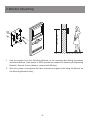
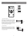
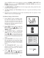
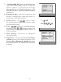
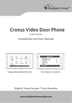
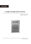
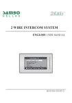
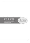
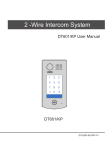
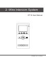
2 -Wire Intercom System
DT16 User Manual
UNLOCK
TALK
F2
F1
MENU
CALL
MONITOR
DT-ENG-16-V1 100S415
PRECAUTIONS
●●
Please read this manual through before using the product.
●●
Don't install or make any wire terminations while power supply is plugged in.It can
cause electrical shock or damage to the unit.
●●
All parts should be protected from violence vibration. And don't allow to be impacting,
knocking and dropping.
●●
For clean the LCD screen, using hands or wet cloth is forbidden.
●●
Please do the cleanness with soft cotton cloth, don't use the organic or chemical clean
impregnate. If necessary, use pure water or dilute soap water to clean the dust.
●●
Image distortion may occur if the video door phone is mounted too close to magnetic
field e. g. Microwaves, TV, computer etc.
●●
Please keep away the video door monitor from wet, high temperature, dust, caustic
and oxidation gas in order to avoid any unpredictable damage.
●●
Don't open the device at any condition, call for help if there are any problems.
CONTENTS
1.Parts and Functions................................................. 1
2.Monitor Mounting..................................................... 2
3.System Connection.................................................. 3
4.Operations................................................................ 4
4.1 Answering a door call........................................ 4
4.2 Door release...................................................... 4
4.3 Entrance monitoring.......................................... 5
4.4 Intercom function............................................... 5
4.5 Image and Volume Adjust................................. 5
4.6 Basic Setup Instructions..................................... 6
5.Specifications........................................................... 8
1.Parts and Functions
1
2
3
13
4
UNLOCK
F2
F1
CALL
5
6
7
14
8
ON
123456
TALK
MENU
MONITOR
15
9
10
11
16
12
1.
LCD Screen
10. Direction Button
2.
Microphone
11. TALK Button
3.
Second UNLOCK Button
12. Speaker
4.
Staircase Light Button
13. Connection Port
5.
LED Indicator
14. Extend Port
6.
CALL Button
15. DIP Switches
7.
UNLOCK Button
16. Mounting Hook
8.
MENU Button
9.
MONITOR Button
-1-
145~160 cm
2.Monitor Mounting
1. Use the screws to fix the Mounting Bracket on the mounting box.(fitting accesories
includes a Bracket (Two pieces of 4X25 screws are needed for fastening the Mounting
Bracket), Special 2 wire cables to connect with Monitor)
2. Wire the system correctly(see the later connection chapter) then hang the Monitor on
the Mounting Bracket firmly.
-2-
3.Monitor Extending Connection
L1
L2
SW+
SWEXT-RING
GND
VIDEO
ON
123456
DIP
ON
123456
1. Door Bell Call Button
Additional door bell call button can be connected
to the Monitor, so that the visitors can ring the
door bell again in front of the user's apartment.
When the call button is pressed, the Monitor
will output ring tones but the screen will keep
off, and the external ringer will ring at the same
time(if a external ringer is installed).
2. External Ringer
External ringer can be connected to the Monitor.
The ringer will ring whenever the Door Station
call button or the door bell call button is pressed,
and it will stop ringing when the Monitor rejucted
or answered the call.
Door bell call button
External Ringer
-
+
12Vdc 300mA
-3-
SW+
SWEXT-RING
GND
VIDEO
SW+
SWEXT-RING
GND
VIDEO
4.Operations
4.1 Answering a door call
1. Press "CALL" button on doorstation.
2. The monitor rings,and the visitor will be seen on video monitor.
note: the screen turns off after 40 seconds if nobody answers.(40
seconds is default,it can be set by yourself)
UNLOCK
TALK
F2
F1
MENU
CALL
MONITOR
3. Press "TALK" button,you can communicate hands free with the visitor for 90 seconds.
After finishing communication,press "TALK" button again to end the communication.
UNLOCK
F2
F1
CALL
press "TALK" button again
UNLOCK
CALL
F2
F1
end the communication
TALK
MENU
MONITOR
TALK
MENU
MONITOR
4.2 Door release
1. During communication,press "UNLOCK" button to
release the door.(If two locks connected to door
camera,press a lock button to open the matching
lock)
UNLOCK
TALK
-4-
F2
F1
MENU
CALL
MONITOR
4.3 Entrance monitoring
1. Press "MONITOR" button when in standby.
UNLOCK
2. The screen will display the image from door
station.
F2
F1
TALK
MENU
CALL
MONITOR
3. Press"MONITOR" button again to end
monitoring.
Intercom Function
4.4 Intercom function
Intercom Call
Inner Call
1. Press "CALL" button in standby mode to enter
intercom function page.
Direct Dial Guard Unit
Exit
2. Intercom Call: User in one apartment can call
other apartments in the system. Use
/
to
select the item and press MENU button to enter
the Name List page. (the namelist will be created
automatically by the system). Selete a name on
the screen then press CALL Button to call.Use
/
button to scroll to Last / Next name list page.
note:1. Press "CALL" button again to redial. 2.
Press "TALK" button to cancel the call.
- Name List [01] Mr A
[02] Mr B
[03] Mr C
[04] Mr D
[05] Mr E
3. Inner Call: If multi Monitors are installed in the same apartment, select Inner Call
all the other Monitors will ring at the same time, whichever Monitor answers the call,
conversation is started.
4. Direct Dial Guard unit: A Monitor can be assigned as Guard Unit Monitor; when the
Guard Unit Monitor answers the call, conversation with the guard person is started..
4.5 Image and Volume Adjust
1. D u r i n g m o n i t o r i n g o r t a l k i n g , p r e s s
“MENU"button,the ADJUST MENU will be
displayed.
user
scene
5
Brightness
RGB
/
2. Press
to decrease or increase the
value; Use
/
button to select the next
adjustment item.
3. The first item is Scene mode selection:
-5-
4
Colour
2
Ring Volume
Talk Volume
6
Total 4 SCREEN modes can be selected in sequence: NORMAL, USER, SOFT and
BRIGHT. Whenever you modify BRIGHTNESS or COLOUR, SCENE item will be set
to USER mode automatically.
4. The BRIGHTNESS and COLOR item is for the image quality setting, adjust the value
to get the best image you like.
5. The Ring Volume and Talk Volume items are ring tone and talking volume
adjustment.
6. Note that all the modifications will be done immediately after the operation. Press
"MENU" button to quit the adjust page.
4.6 Basic Setup Instructions
1. Press "MENU" button in standby mode,
the date/time page will be dispalyed.
The first line shows the current time, the
second line shows the current date and
weekday.(the date/time page will close in
3 munite if no operation).
4
2. Press "MENU" button again to enter the
MAIN MENU, Use
/
button to
select the SETUP MENU,and then press
"MENU" button.
3. The OUTDOOR TONE and INTERCOM
TONE item are for chord ring selection.
Press
/
to increase/decrease the
value. (alternatively, press the item itself
in sequence to increase/decrease the
value)
4. AUTO RECORD:If the item is set to
ON, the Monitor will record the image
automatically in 2 seconds after the visitor
pressed the CALL Button on the Outdoor
station.
5. T h e A D VA N C E D S E T. . . i t e m i s f o r
advance settings. a password will be
asked before entering. The default
password is 2008.
6. Press
/
button to increase/
decrease the value,Press
/
button
to select the location,after finishing,press
MENU button to enter next step.
-6-
monitor
intercom
setup
exit
Outdoor Tone
--
01
Intercom Tone
--
05
Monitor Time
-- 1min
Advanced Set...
Auto Record
--
OFF
Exit
Password: 0
***
7. The Slave Addr Set item is for the master and
slave user code setting, if there is only one
Monitor installed in one apartment, set to 0,if
there are two,set to 1,if there are three,set to 2,if
there are four,set to 3,and the maximum extend
monitor is 4.
Slave Addr Set
--
0
Guard Unit Set
--
0
Date/Time Set...
Other Settings...
Information...
Exit
8. Guard Unit Set: if the item is set to 1, the
Monitor is assigned as a Guard Unit Monitor, for
normal users, it should be set to 0.
9. Date/Time Set...: Use
/
button to select
the item.and then press MENU button to enter
time/date setting page.
10. Press
/
button to increase/decrease
the value,Press
/
button to select the
location,after finishing,press MENU button to
save the settings.
11. Other Settings...: this item is for adding and
deleting Remotes.
12. Information...: this item will show the hardware/
software version and voltage information of the
Monitor. Select Restore to default item ,then
press MENU button. All settings will be restored
to default.
-7-
Time 1 1 : 3 5
Date 2 0 0 9 0 2 1 4
Hardware ver
0302
Software ver
0168
Voltage
22.4V
Manufacture
00.0T
Restore to default
Exit
5.Specifications
●● Power supply: DC 24V
●● Power consumption:
Standby 2W; Working 5W
●● Monitor screen:
3.5 Inch color TFT-LCD
●● Display Resolutions:
320(R, G, B) x 240 pixels
●● Dimensions:
220(H)×105(W)×20(D)mm
-8-
The design and specifications can be changed without notice to the user. Right to
interpret and copyright of this manual are preserved.
DT-ENG-16-V1 100S415