1
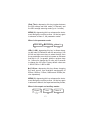
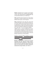
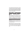
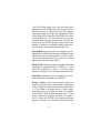
Wilcom
FiberRanger 3
Mini-OTDR
USER’S MANUAL
Avoid exposure
Laser Radiation Emitted
from the aperture.
This product conforms to CDRH standards for laser product
Per 21 CFR 1040.10 & 1040.11
FiberRanger3 mini-OTDR
Operating Instructions
813-159-007
August 2007
Copyright (c) 2004, 2005, 2006, 2007 Wilcom
All Rights reserved
Wilcom reserves the right to make changes to the material
contained herein without notice and shall not be liable for
errors contained herein or for incidental, consequential damage in connection with the furnishing, performance or use of
this material.
This document may not be copied or duplicated in part or in
whole for any purpose without the express written permission
of Wilcom.
i
Table of Contents
SECTION
PAGE
1.0 Introduction ………………………………….................1
Instrument Description
2.0 Preparation for Use …………………...........................4
Inspection
Identification / Configuration
Power Requirements
Unit Configuration
3.0 Cautions
………………………….................................7
Batteries
Laser Safety
4.0 Features
………........................................................…9
Mechanical
Functional
5.0 Operation
…………………………................................11
Functional Description of Membrane Keys
Functional Description of Display
Functional Description of Event Table Display
6.0 Maintenance
……………………..................................22
Battery Replacement
Laser Out Port
Recalibration and Verification
7.0 Application Information …………...............................24
Optical Time Domain Reflectometer Measurements
Applications and Results
8.0 Troubleshooting
9.0
…………………...............................29
Instrument Specifications
10.0 Service and Repair
11.0 Version Control
……................................30
……..…….................................33
……........…….................................34
ii
1.0
Introduction
The Mini-OTDR is the first low cost portable Optical
Time Domain Reflectometer with the core functions
required to measure optical fiber from one end during installation, repair and verification. The MiniOTDR is equipped with a 4" QVGA graphics presentation of fiber loss vs distance, single to Quad Laser
sources, and a quick reference instruction card in
the ruggedized lid. The instrument is designed for
stand-alone operation or connection to an optional
printer or PC through the RS232 Export feature. The
ruggedized mini-OTDR is contained in a compact,
rugged plastic housing, with watertight, extremely
heavy-duty protection when sealed. All controls are
accessible via a 9 key weatherproof membrane or
conductive rubber keypad, offering simple, straightforward functionality. Measurement data and mode
indication is supplied via the QVGA LCD display that
offers expandable trace fiber data, mode and parameter enunciation, and soft key control for easy viewing and sunlight readability.
The mini-OTDR is capable of measuring splice loss
or link attenuation. The singlemode and multimode
output ports use high power, 850, 1300, 1310, 1490
or 1550 nm pulsed laser source. The backscatter receiver uses a temperature compensated avalanche
photodiode for reliable, stable performance in fiber
links from tens of meters to over 64Km. A 50MIPS,
high-speed microprocessor, provides the N-point
averaging function and control for <1/4 second Real
Time update rates or 65K trace averages in <1
minute.
1
Introduction ( cont )
The QVGA monochrome display provides a powerful yet simple set of fiber parameters and control indications to view an entire fiber link or zoom in and
analyze a splicing point or defect in the fiber. The
display shows the fiber loss vs distance in its large
central graph. The scales are automatically updated
for expansion modes and positioning of the dual line
cursors used for loss and distance measurement.
Individual and dual cursor measurements are spelled
out as well as important instrument parameters such
as Index Of Refraction, pulse width, scanning speed,
and a battery gauge. Programmable soft-key menus
are updated for instrument modes of measurement,
scanning, or auxiliary parameters.
The 9 key membrane keypad provides simple
straightforward commands to take a scan, make
measurements or navigate the soft-key menus. A new
scan is accomplished as easily as pressing the Scan
button, within 1/4 second fiber trace data is accessible. To automactically adjust for an unknown fiber
length, hold the scan key down for 2 seconds.The
soft-key menus are navigated by 3 buttons to provide manipulation of graph expansion and cursors,
or selecting important parameters such as pulse
width, index of refraction or laser wavelength. Exporting data or controlling special functions such as
display contrast or loss mode are available in the
auxiliary menu structure.
The Print / Store / Recall / RS232/ MEMDUMP export features are useful for analyzing previously taken
fiber trace data either on the graphics panel or viewed
on a PC or printer. The storage of trace data is made
to a 255 step table. Data can be retrieved via soft-
2
Introduction ( cont )
key entry and the entire table can be scanned on the
graphics panel. The data is transmitted to a personal
computer or directly to a thermal printer via the RS232
port.
The previous single or dual wavelength LAN (high
resolution) version min-OTDR units were designed
for shorter distances of fiber (1Km, 4Km or 16Km
spans) with higher resolution capability (1m, 4m or
16m). The single or dual wavelength Long Range
(LR) version min-OTDR units have longer distance
capabilities (4Km, 16Km or 64Km spans) using lower
resolution sampling (2m, 8m, or 32m). The latest ‘C’
series mini-OTDR units incorporate Triple or Quad
wavelength capability, and both the LAN (L) and Long
Range (LR) distance and resolution selections.
For a quick start refer to section 5.1 page 8, or the
Quick Reference card inside the cover.
3
2.0
Preparation for Use
2.1
Inspection
Before shipment, this instrument has been inspected
and found to be in perfect working order and free of
defects.
The shipping carton should contain the following:
1. Mini-OTDR, configured as ordered with 8 - AA
NiMH Batteries installed
2. AC/DC Charger
3. RS232 mini stereo jack to RJ11 modular cord,
Printer adaptor, PC adaptor
4. Users Manual
2.2
Instrument Identification/ Configuration
The instrument’s Model, Part Number, Serial Number, Date of Manufacture and Configuration are indicated on a label located inside the cover of the unit.
The instrument’s history is filed at the factory by part
number and serial number.
2.3
Power Requirements
The instrument is equipped with an AC/DC charger
which recharges the unit’s internal NiMH batteries
(8 - AA, 2500mA hours). Depending on usage, this
will typically enable 10 to 12 hours use with a fresh,
fully charged battery pack. Typical recharge time is 6
- 8 hours. The AC/DC adapter which is ordered separately can be either a 110VAC to 12VDC @ 800mA
tip positive or 220VAC to 12VDC @ 800mA tip positive (customer specified). Installation of other batteries may cause instrumentation damage and will void
the warranty.
4
If batteries are installed that are dead or less than 1
volt each, then charge these batteries for one (1) hour
before using the mini-OTDR
WARNING: To Prevent Fire or Shock Hazard: Do
not install other battery types; Do not use the AC
adapter without the batteries installed; Do not expose
the AC adapter to rain or excessive moisture; Do not
use the AC adapter when there are signs of damage
to the enclosure or cord; Ensure that you are using
the correct adapter for the local line voltage; Do not
use any other adapter than the one provided with this
instrument. Any other condition will void your warranty.
2.4
Unit Configuration
See the label inside the cover for the unit configuration.
Figure 2.1 contains a front view of the unit.
5
Front View of Mini-OTDR
figure 2.1
6
3.0
Cautions
3.1
Batteries
This unit is equipped with and has been designed to
use NiMH rechargeable batteries. Replace batteries only with Nickel-Metal-Hydride Rechargeable
batteries. Do not use the charger if the supplied NiMH
batteries are replaced with Alkaline or another battery type. Installation of alkaline batteries may cause
instrumentation damage and will void the warranty.
WARNING: Do not use the AC adapter without the
batteries installed.
If installed batteries are dead or less than 1 volt each,
charge these batteries for one (1) hour before energizing the Mini-OTDR.
3.2
Laser Safety
The Mini-OTDR has been configured with laser diodes having central wavelengths of 850nm, 1300nm,
1310nm, 1490nm or 1550nm. The unit has been
designed to comply with 21 CFR (Code of Federal
Regulations) 1040.10 and 1040.11, for Class I emission limits. Although the FDA does not consider Class
1 levels to be hazardous, we suggest limiting exposure by not looking directly into the laser aperture.
Also, do not under any circumstance view or inspect the laser output fibers or connectors through
collimating or focusing optics unless the unit is turned
off, batteries are removed and power adapter is disconnected.
7
Inside cover of the Mini-OTDR to describe location of labels
Quick Reference
Card
Laser Safety
Label
Serial Number
Date of Manufacture Label
8
4.0
Features
4.1
Mechanical
Instrument Enclosure
The Mini-OTDR is housed in one of the most rugged
plastic enclosures available. With the lid closed and
locked, and the purge port tightened, this enclosure
is air and water-tight. The purge port is supplied to
temporarily balance the inside and outside air pressure to facilitate opening the unit after using it in higher
altitude environments. Remember to retighten the
purge port after every use. Although the front panel
membrane keypad is weather resistant, care must
be taken to avoid liquids and contaminants around
the fragile optical and electrical connectors, and the
glass display. Use a mild cleaning agent and damp
soft cloth to clean up the panels and the outside case.
See the maintenance section to clean the optical connector. NEVER open the instrument behind the membrane keypad panel for cleaning. Return to the factory for servicing if necessary.
Mini-OTDR Packaging
The instrument is shipped in a protective cardboard
container along with the charger, RS232 connectors,
and this manual. Save the protective packaging for
storage and shipment.
4.2
Functional
Power Save
The Mini-OTDR incorporates a battery save feature
that allows for maximum utilization of the battery life.
Upon turning the unit on, it keeps track of the keypad
activity.
9
If no key presses are detected for a period of
approximately 15 minutes, the unit will automatically
turn itself off, storing the current mode settings. To
disable this feature, enter the auxiliary menu auto-off
feature and select Auto-DIS. To enable this feature
select Auto-ENB. When enabled, an “a” appears next
to the battery gauge on the LCD display.
Low Battery and Power Shut Down
The Mini-OTDR incorporates battery monitoring circuitry to manage the discharge and inform the user
when the battery charge is approaching an unsatisfactory level. A battery gauge is displayed on the
graphics panel that shows relative battery charge
depth. When approximately ninety percent of the battery capacity has been expended, the gauge shows
empty, indicating to the user that the batteries need
recharging, and allowing a short period of time to finish using the instrument. The unit automatically powers down when the batteries become fully discharged.
Printing
The Mini-OTDR incorporates a printing feature available in the Export menu. A Sipix A6 serial thermal
printer driver is built into the instrument firmware.
Using the modular serial cable and the 9 pin DB9
male adaptor supplied with the Mini-OTDR, connect
to the serial cable supplied with the printer. When
energizing the printer, allow 5 seconds for the
formfeed before pressing the print key.
10
5.0
Operation
5.1
Functional Description of Membrane Keys
SCAN
Turns the unit On and Off.
Depressing this key will cause the unit to start another scan or stop the current scan. Holding the key
down for 2 seconds causes the unit to automatically
(AUTO) search for 1 minute (when in SCAN mode)
for the end of the fiber and adjust the distance range
and pulse widths accordingly. At the end of the search,
DONE will be displayed. To enhance data acquisition speed, while scanning the keyboard is monitored
every 1/4 second for further key activity. This can
cause a slight delay in keyboard response.
∇
∆
∇
On
Off
∇
F1
F2
F3
Arrow Keys: left and right are used
to move the cursors. Up and down
are used to change appropriate
settings dependent on operational
mode. In V2.1 or greater, hold the
up/down keys for 1 second to
change the 10 units, and 3 seconds to change the 100 units.
Function Softkeys F1, F2 or F3
These keys are graphics display definable keys and will execute the command immediately above the key dependent on operational mode as explained below. The currently selected
function is highlighted.
11
When in the cursor mode:
Zoom 1x
Cursor B
F1
F2
Menu 1
F3
ZOOM (1)x: depressing this key enables the user to
expand around the current cursor selected. The expansions available on the vertical loss scale are 4dB,
2dB, 1dB, and 0.5dB / division. Depending on pulse
width and extended or normal distance selection, the
expansions available on the horizontal distance scale
are 16Km, 8Km, 4Km, 2Km, 1Km, 500m, 250m,
125m, 64m or 32m/div (or corresponding expansions
in Kilofeet). Subsequent key presses expand to the
next level than back to 4dB & 16Km / division.
CURSOR (B): depressing this key allows selection
and expansion around the B or A cursor. The left and
right arrow keys then control the location of the selected cursor, and the zoom key controls expansion
around that cursor.
MENU (1): depressing this key advances the instrument through the soft key menus. Hit the key once to
advance to Menu 2, the pulse width and average
modes.
When in the pulse width and average modes:
RealTime
Long PW
F1
F2
Menu 2
F3
(Long) PW: depressing this key toggles between 4m/
13 ft short pulse, 50m/164ft medium pulse (C or LAN
versions), and 100m/328 ft long pulse (C or Long
Range versions).
12
(Real Time): depressing this key toggles between
the 256 average real time mode (1/4 second), and
the 65K average scanning mode (up to 1 minute).
MENU (2): depressing this key advances the instrument through the soft key menus. Hit the key again
to advance to Menu 3, the parameter modes.
When in the parameter mode:
IOR=1.468
λ
λ=1310nm
F1
F2
Menu 3
F3
IOR=( 1.468): depressing this key in allows changing the Index Of Refraction with the arrow keys. Use
the left and right arrow keys to select the digit, then
the up and down arrow keys to increase or decrease
that digit. In V2.1 or greater, hold the up/down keys
for 1 second to change the 10 units, and 3 seconds
to change the 100 units. Factory default values are
1.468 for SM or 1.486 for MM.
λ=(1310)nm: depressing this key allows changing
the laser source from available wavelengths of
850nm, 1300nm, 1310nm, 1490nm and 1550nm (device dependent).
MENU (3): depressing this key advances the instrument through the soft key menus. Hit the key again
to advance to Menu 4, the export and auxiliary modes,
When in the export and auxiliary modes:
∆ Export ∆
∇
∇
∆ Auxl. ∆
∇
∇
Menu 4
F1
F2
F3
13
Export: depressing this key enters into the Export
function secondary menu. Available export features
are Print, Store, Recall, RS232, and MEMDUMP. This
can be selected with the up or down keys.
Print: depressing this key sends the current screen
information to a Sipix A6 thermal printer through the
RS232 electrical port on the front panel.
Store: depressing this key saves the current trace
and data information into the displayed storage location. After selecting the function with the first Store
key depression, use the left and right arrow keys to
select the storage location digit, then the up and down
arrow keys to increase or decrease the storage location (1,2,3..255,1..). In V2.1 or greater, hold the
up/down keys for 1 second to change the 10 units,
and 3 seconds to change the 100 units. Each subsequent depression of the Store key will save the current trace data into that storage location, then autoincrement the counter to the next location. Press the
Escape or Menu key to exit this feature.
Example: If the Store SoftKey “displays” 145, when
you depress the Store Key the trace will be stored to
position #145, then the displayed number will increment to now read 146.
Recall: depressing this key recalls the trace and data
information from the “displayed” storage location.
After the first Recall key depression, use the left and
right arrow keys to select the storage location digit,
then the up and down arrow keys to increase or
decrease the storage location (1,2,3..255,1..).
14
In V2.1 or greater, hold the up/down keys for 1 second
to change the 10 units, and 3 seconds to change the
100 units. Each subsequent depression of the Recall
key will recall the current storage location and display
the trace and data information, then auto-increment
the counter to the next location. Press the Escape or
Menu key to exit this feature.
Example: If the Recall SoftKey “displays” 145, when you
depress the Recall Key the trace will be the one stored at
position #145, then the displayed number will now read
146.
RS232: depressing this key transmits the current
trace and data information out the RS232 stereo minijack on the front panel. The transmission mode is
selected in the auxiliary menu, with choices of
115200,8,n,1 or 57600,8,n,1 with no flow control.
Please call you sales representative if you would like
to purchase the Mini-OTDR Certification Software.
MEMDUMP: depressing this key transmits all stored
traces and data information. Transmission takes approximately 4 seconds per active stored trace; to abort
press MEMDUMP again.
Auxl: depressing this key enters into the Auxiliary
function secondary menu. Available Auxiliary features
are LCD Contrast, Loss mode, Auto Off mode, Baud
rate mode, Distance Mode, Range Mode and Back
Light. Each can be selected with the up or down
keys.
15
LCD Cont: depressing this key allows changing the
LCD contrast to brighten or dim the display. After
selecting the function with the first key depression,
use up and down arrow keys to increase or decrease
the contrast from 0 to 9.
Loss=(2pnt): depressing this key toggles the displayed loss measurements between 2 Point, Splice
Loss and dB/Km(dB/Kft) method.
2 Point loss method takes the difference in vertical
height between where the A and B cursors cross the
fiber trace to determine loss.
The dB/Km(dB/Kft) loss method takes the 2 Point
loss in dB and divides by the distance between the
cursors in Meters(Kilofeet). For accurate dB/Km loss
measurements, the two cursors must be on level
backscatter points at least ~256m apart (NA will show
for distances that are too short).
Splice loss method takes the loss around cursor A or
B (chosen by the F2 key in the Cursor Menu 1). Setting the cursor at the beginning of an event such as
a reflection, the Metro unit (and ‘A’ series Xtnd mode)
takes the average of the past 256 meters/Long pulse
(64 meters/Short pulse) before the cursor. The unit
then skips 256 meters (64 meters Short pulse) over
the event then averages the next 256 meters (64
meters Short pulse) to subtract from the first average. The loss between these regions is adjusted for
512 meters (128 meters Short pulse) of typical fiber
loss. The LAN unit (and ‘A’ series Normal mode) takes
the average of the past 128m/420ft XM mode (32m/
105ft Long pulse, 8m/26ft Short pulse) before the
cursor. The unit then skips 128m/420 ft Long pulse
16
(32m/105ft Short pulse) over the event then averages the next 128m/420ft (32m/105ft Long pulse, 8m/
26ft Short pulse) to subtract from the first average.
The loss between these regions is adjusted for 256m/
840ft (160m/525ft Long pulse, 40m/130ft Short pulse)
of typical fiber loss. For accurate Splice Loss measurements the averaged areas before and after the
splice must be level backscatter regions free from
defects or splices. A consistent reading while moving the cursor a few meters verifies flat levels.
Auto=(ENB): depressing this key toggles the unit
between Auto-Off function enabled or disabled. When
enabled the unit will automatically turn itself off after
15 minutes of keyboard inactivity, and an “a” for auto
appears next to the battery gauge.
Baud=(115K): depressing this key toggles the RS232
transmission speed between 115200,8,n,1 (115K
baud rate, 8 data bits, no parity, 1 stop bit, no flow
control) or 57600,8,n,1 for hookup to an external PC.
Dist=(Km): depressing this key toggles the unit between measuring kilometers and Kilofeet.
Range = (Xtnd): used to select shorter (Norm) or
longer (Xtnd) sections of fiber analysis. Depressing
this key toggles the Metro unit between normal mode
= 16 Km range or extended mode = 64Km range.
Depressing this key toggles the LAN unit between
normal mode = 4Km range or extended mode = 16Km
range. Depressing this key multiplies the range in
the ‘C’ series mini-OTDR unit short/medium/long
pulse by a factor of 4, 1Km/4Km/16Km becomes
17
4Km/16Km/64Km. When in the extended mode an
“x” appears in the horizontal scale factor display.
BkLt=(ON): depressing this key toggles the display
backlight off and on. Battery operation time is somewhat longer with the backlight off.
MENU (4): depressing this key again to advance
the instrument to Menu 5, the event table mode.
When in the Event Table Mode:
Splice >.1
Show Trace
Menu 5
Splice>(.1): depressing this key selects the sensitivity
option of the event analysis. Splice>.1 provides the
highest sensitivity option which will search for and
display many events in the fiber down to 0.1dB loss
for non-reflecting splices and low level reflections and
gains. The medium sensitivity displays less events
only going down to 0.2dB and more intense
reflections. The lowest sensitivity option displays the
least amount of events, down to 0.5dB splice and
even higher levels of reflections required. The highest
sensitivity should be used for high signal level, low
noise, long pulse, averaged traces. Noise pickup in
the event table can be reduced by decreasing the
sensitivity to 0.2 or 0.5dB ranges. Due to noise on
the trace and oddly shaped fiber perturbations, not
all events will be displayed, even with the highest
sensitivity settings. To enable detection of splices
down to 0.1dB and minimize the display of ‘false’
events, maximize the fiber signal level with the
longest appropriate pulse width, and minimize the
noise with the longest averaging.
18
Show (Trace): depressing this key toggles between
the Trace or Event Table display modes. When
scanning, selecting the event table mode will halt the
current scan. In Event Table mode, up to 10 possible
events will be displayed. The last saturating event
peaking at >23dB (or if none the last event) will be
shown as the possible end of link. A link analysis of
total distance, 2 point loss, and dB/Km loss will be
displayed at the table bottom. See fig. 5.3 for a
functional description of the Event Table.
•
Note: When examining events be aware that
each event has a subsequent dead zone that will hide
following events for a short period, approximately 8
points for a non-saturating reflection, or approximately
16 points for a saturating reflection or loss. In the
short medium and long pulses each point is 1, 4 and
16 meters respectively (2, 8 and 32 meters for
extended mode).
•
Note: Auto event analysis provides
approximate loss and distance measurements to
quickly assist in network evaluation. Automatic
detection results are not guaranteed and have their
limits, possibly causing erroneous readings or
detection failure. User interaction by interfacing with
the trace display is recommended for final qualitative
and quantitative analysis.
MENU (5): depressing this key again returns the
instrument to Menu 1, the cursor mode.
19
5.2
Functional Description of Display
Cursor Distance
Measurements
Fiber Trace of
Loss vs Distance
Cursor Loss Measurements
2 point, splice loss, or dB/Km
Index of Refraction and
PulseWidths
Scanning
Indicator
Wavelength
Averaging
Mode
Vertical
Scale
Battery
Gauge
Horizontal
Scale
Dual Adjustable
Cursors
Soft Keys
20
5.3
Functional Description of Event Table
Event
Marker #
Event
Distance
Localized
Loss
Loss in
dB/Km
Loss from
previous event
Type of event
SPL = Splice
SAT = Saturated
GAN = Gainer
Reflecting
ORL
Possible
End?
Sensitivity
Link
Results
Possible
End?
Sensitivity
Cutoff
Toggle Trace
& Event Table
21
6.0
Maintenance
6.1
Battery Replacement
In the event the batteries fail to retain a sufficient
charge and need to be replaced, contact the factory
for service. If you wish to replace the batteries in the
field, extreme care must be taken not to damage
the internal fibers, flex strip wiring or the instrument electronics. This damage will void the warranty. At all times protect the fiber connector and internal instrument from adverse environmental conditions.
Replace the batteries with 8 NiMH AA cell 2500 mA
hour batteries, Energizer or equivalent. The batteries are accessible via 2 sliding latched covers inside
the unit. This requires removal of the front panel and
circuit board pack from the ruggedized case. To remove the front panel, turn power off and disconnect
all electrical and fiber cords. Remove the 4 knurled
knobs and their fiber washers from the front panel,
pull the front panel out gently, taking care not to damage the internal fiber or electrical cords. Remove the
screws from the 2 black plastic battery covers on the
back of the circuit board pack, then slide the covers
off. Replace the batteries taking care to install them
properly as depicted in the battery holder diagrams.
Replace the battery covers and screws. Very carefully install the circuit board pack and front panel into
the rugged case being certain that the fiber and electrical cords are free from kinks. Tighten down the
knurled knobs with their fiber washers while gently
pressing on the front panel corners. If the instrument
fails to function properly contact the factory for service.
22
6.2
Laser Out Port
In order to maintain a low loss fiber connection, care
should be taken to adequately clean the ferrule of
any connector to be inserted in the Laser Out port. In
the event that the port needs to be cleaned, we suggest the use of isopropyl alcohol and foam swabs
specifically designed for cleaning connectors accepting 2.5mm ferrules.
Do not under any circumstance view or inspect the
laser output fibers, connectors, or the fiber under test
through collimating or focusing optics. A video inspection microscope should be used to examine all fiber
ends. Contact your Wilcom sales representative for
video microscope information.
6.4
Recalibration and Verification
Periodic verification of the MINI-OTDR is recommended to ensure that your instrument remains within
specification. Although not imperative, we recommend a recalibration and verification once a year to
make certain the instrument is functioning properly
and performing to its rated specifications. Consult
the factory for service.
23
7.0
Application Information
7.1
Optical Time Domain Reflectometer
Measurements.
The Mini-OTDR is designed to be used as an installation, troubleshooting, and maintenance tool for
short to medium haul fiber networks. The Mini-OTDR
is a full featured Optical Time Domain Reflectometer, but unlike OTDRs that cost thousands of dollars
more, the Mini-OTDR is very simple to operate.
The Mini-OTDR measures distance and loss of fiber links up to 64Km/215Kft by launching an optical
pulse down one end of the fiber and analyzing the
returned energy in time (or distance) from reflections. The Mini-OTDR uses an advanced high speed
embedded controller and display processor with proprietary technology to analyze, store and average
the fiber trace data in the quickest time. This high
speed processing engine allows the user to make
distance and loss measurements immediately after
energizing the instrument. With its advanced Event
Table, Splice Loss Mode and dB/Km Mode, it also
can assist the user in interpreting major events such
as bad splices, connections or broken ends. Minor
perturbations along otherwise normal fiber links can
also be detected using a simple moving cursor approach in Splice Loss Mode. Complex return signals with many major or minor events can be analyzed by the Mini-OTDR then stored away for
archiving and later retrieval.
With the Mini-OTDR there are a few parameters of
interest to assist in obtaining reliable, consistent
24
measurements. The user must be aware of the Index of Refraction of their fiber or cable, the appropriate pulse width to use for their application, and
the associated dead zones from that pulse width.
These features can be modified via the instrument
menu structure. See section 5.
The fiber Index of Refraction (IOR) is an important
parameter that must be entered by the user to maximize the distance measurement accuracy. The IOR
is proportional to the speed of light in glass compared to the speed in a vacuum and can be calculated by the equation IOR = C (the speed of light in
a vacuum) / V (the speed of light in fiber). The IOR
number can be obtained by the fiber or cable manufacturer or can be calculated with a known length of
cable. IOR numbers generally fall around 1.468 SM,
1.486 MM, the default value, but can be adjusted
from 1.0 to 2.0.
To calibrate the IOR for your particular fiber, take a
known distance of fiber or cable (best if around
1 kilometer), and measure the distance with the MiniOTDR set for short pulse, changing the IOR until
the measured distances closely match. An error of
.001 of the IOR entry (1.468 vs 1.469) equates to
an error of approximately 0.7 meters per kilometer
of distance measured.
The pulse width, the other important user entered
parameter, will affect the capability of measuring
distance to major events. For Long Range units,
the short pulse is recommended for short distances
of fiber between 10m/33ft and 4Km/13Kft. The long
pulse is recommended for longer distances up to
25
64Km/215Kft. The dead zone, or initial signal saturation for the first few meters, is ~10m/33ft for short
pulse and ~100m/328ft for long pulse. Also the measurement resolution changes from 2m/6ft for the
short pulse, to 8m/25ft (32m/105ft Xtnd) for long
pulse. For LAN, short distances of fiber, between
5m/16ft and 1Km/3.3Kft, the short pulse is recommended. The long pulse is recommended for longer
distances up to 16Km/53Kft. The dead zone, or initial signal saturation for the first few meters is ~6m/
20ft for short pulse and ~50m/160ft for long pulse.
Also the measurement resolution changes from 1m/
3ft for the short pulse, to 4m/13ft (16m/52ft Xtnd)
for the long pulse. The ‘C’ series acts like a LAN (L)
in normal mode and a Long Range (LR)in extended
mode.
26
7.2
Applications and Results.
Typical applications and expected results for the short
pulse are as follows:
•
•
•
•
•
•
•
•
•
The short pulse takes approximately ¼ second to
update a 256 average RealTime scan, and up to 1
minute for up to 65K average scan.
Minor events can be measured using the short pulse
and the scanning mode to reduce the noise seen on
the fiber backscatter.
Long Range (LR) units (and ‘C’ series Xtnd mode):
When measuring down to 10m(33ft), events can be
detected within +/-2m(6ft).
When measuring up to 4Km(13Kft), events can be
detected within approximately +/-0.7m/Km(2ft/Kft).
Short pulse will not work properly with fibers over
16Km(52Kft) in length, use long pulse.
LAN (L) units (and ‘C’ series Normal mode):
When measuring down to 5m(16ft) and up to
1Km(3.3Kft), events can be detected within +/1m(3.3ft).
Short pulse will not work properly with fibers over
8Km/22Kft in length, use long pulse.
Typical applications and expected results for the medium
pulse (‘C’ series only) are as follows:
•
•
•
Xtnd mode:
When measuring greater than 50m(164ft), events can
be detected within +/- 8m(25ft).
When measuring up to 16Km(53Kft) events can be
detected within approximately +/-0.7m/ Km(2ft/Kft).
27
•
•
•
Normal mode:
When measuring greater than 50m/164ft and up to
4Km/13Kft, events can be detected within +/-4m(13ft).
Medium pulse, Normal mode will not work properly
over 16Km/53Kft.
When measuring up to 16Km/53Kft events can be
detected to within approximately +/- 0.7m per Km
(0.7ft/Kft)
Typical applications and expected results for the long pulse
are as follows:
•
•
•
•
•
•
•
It is difficult to measure smaller reflective events
(APC/UPC connectors or mechanical splices) in the
long pulse, use the short pulse for up to 1Km(3.3Kft)
LAN (L), 4Km(13Kft) Long Range (LR).
Long Range (LR) (and ‘C’ series Xtnd mode):
When measuring greater than 100m(330ft), events
can be detected within +/-8m(25ft) (32m/105ft Xtnd).
When measuring up to 64Km events can be detected
within approximately +/- 0.7m/Km(2ft/Kft).
LAN (L) (and ‘C’ series Normal mode):
When measuring greater than 100m(330ft) and up
to 4Km(13Kft), events can be detected within +/4m(13ft) (16m(52ft) Xtnd). For LAN (L) units long
pulse will not work properly over 16Km(53Kft), use
Extended mode for up to 64Km(215Kft) of fiber. For
longer lengths of fiber (>64Km/215Kft), use the Long
Range (LR) or ‘C’ series Mini-OTDR.
When measuring up to 16Km/53Kft events can be
detected to within approximately +/- 0.7m per Km
(0.7ft/Kft)
28
8.0
Troubleshooting
Symptom
Possible Cause
Solution
LCD display blank
Power not on.
Batteries require recharging.
Batteries are missing, in backwards
or need replacement
Press ON/OFF key.
Recharge batteries.
Check battery polarity,
replace batteries,or
contact factory for
servicing
Instrument locked up
Unexpected Operational Mode
Remove input power &
a battery for 30 seconds
to reset instrument
Initial
Backscatter low
Defective cord or dirty connector
Fiber Output port requires cleaning
Angle polish mated with UPC polish
Replace or clean cord
Clean port
Examine connector
ends
Extra or “ghost”
Fiber too long for short pulse
reflections on
Fiber over 64Km/200Kft
backscatter (Long Range)
Switch to Long pulse if > 16Km
Switch to Xtnd Mode if > 64Km
Extra or “ghost”
reflections on
backscatter (LAN)
Fiber too long for short pulse
Fiber over 16Km/53Kft
Switch to Long pulse if > 8Km
Switch to Xtnd Mode if > 16Km
Extra or “ghost”
reflections on
backscatter (‘C’ series)
Fiber too long for short pulse
Fiber over 16Km/53Kft
Fiber over 64Km/200Kft
Switch to Med pulse if > 8Km
Switch to Long pulse if > 16Km
Switch to Xtnd Mode if > 64Km
RS232 hookup to PC Baud rate not set properly
not functioning properly or to fast for computer
29
Set baud rate properly or
decrease Baud rate to 57K
9.0
Instrument Specifications - LAN Version
note: specifications subject to change without notice.
LAN (L)
Pulse widths
4m/13 ft(SP)
50m/166ft(LP
Distance interval
1m/3ft(SP)
4m/13ft(LP)
16m/50ft(XM)
Distance Range
1Km/3Kft(SP)
4Km/13Kft(LP)
16Km/50Kft(XM)
Horizontal Expansion
256,128,64,32m/div(SP)
1K,512,256,128m/div(LP)
4K,1K,512,256m/div(XM)
Wavelength of operation
850nm 1300nm 1310nm 1490nm
1550nm (+/-20nm) (device dependent)
Dynamic Range
23dB Typical (LP)
Dead Zone
6m/20 ft Typical (SP)
Averaging Time
1/4 Second (Real Time) up to 1 Minute
(Scanning)
Vertical Expansion
0.5, 1, 2, 4 dB/div
Vertical Resolution
0.01dB
Group IOR Range
1.024 – 2.048
Fiber Connector Type
SingleMode-FC/UPC / Multimode-ST
Data acquisition Method
N-Point Averager
Data Storage
255 traces
Computer Interface
RS-232
Power
8 NiMH AA batteries or 12V Charger (110
or 220VAC)
Size/Weight
7.0 x 4.5 x 3.0" / 2.0lbs. Handheld
8.25 x 6.5 x 3.5" / 2.75lbs. Ruggedized
(SP) = Short Pulse, (LP) = Long Pulse, (X) = Extended Mode
30
9.1 Instrument Specifications - Long Range Version
note: specifications subject to change without notice.
Long Range (LR)
Pulse widths
4m/13 ft(SP)
100m/330ft(LP
Distance interval
2m/6ft(SP)
8m/25ft(LP)
32m/105ft(XM)
Distance Range
4Km/13Kft(SP)
16Km/50Kft(LP)
64Km/215Kft(XM)
Horizontal Expansion
1K, 512, 256,128m/div(SP)
4K,1K,512,256m/div(LP)
16K,8K,4K, 2Km/div(XM)
Wavelength of operation
850nm 1300nm 1310nm 1490nm
1550nm (+/-20nm) (device dependent)
Dynamic Range
23dB Typical (LP)
Dead Zone
6m/20 ft Typical (SP)
Averaging Time
1/4 Second (Real Time) up to 1 Minute
(Scanning)
Vertical Expansion
0.5, 1, 2, 4 dB/div
Vertical Resolution
0.01dB
Group IOR Range
1.024 – 2.048
Fiber Connector Type
SingleMode-FC/UPC / Multimode-ST
Data acquisition Method
N-Point Averager
Data Storage
255 traces
Computer Interface
RS-232
Power
8 NiMH AA batteries or 12V Charger (110
or 220VAC)
Size/Weight
7.0 x 4.5 x 3.0" / 2.0lbs. Handheld
8.25 x 6.5 x 3.5" / 2.75lbs. Ruggedized
(SP) = Short Pulse, (LP) = Long Pulse, (X) = Extended Mode
31
9.2
Instrument Specifications - ‘C’ Version
note: specifications subject to change without notice.
‘C’ Series
Pulse widths
4m/13ft(SP)
50m/166ft(MP)
100m/330ft(LP)
Distance interval
1m/3ft(SP) - 2m/6ft(XSP)
4m/13ft(MP) - 8m/25ft(XMP)
16m/50ft(LP) - 32m/105ft(XLP)
Distance Range
1Km/3Kft(SP) - 4Km/13/Kft(XSP)
4Km/13Kft(MP) - 16Km/50Kft(XMP)
16Km/50Kft(LP) - 64Km/215Kft(XLP)
Horizontal Expansion
256,128, 64, 32m/div(SP) - 1K, 512, 256,128(XSP)
1K, 512, 256,128mm/div(MP) - 4K,1K, 512, 256(XMP)
4K,1K, 512, 256m/div(LP) - 16K, 8K, 4K, 2K(XLP)
Wavelength of operation
850nm 1300nm 1310nm 1490nm
1550nm (+/-20nm) (device dependent)
Dynamic Range
23dB Typical (LP)
Dead Zone
6m/20 ft Typical (SP)
Averaging Time
1/4 Second (Real Time) up to 1 Minute
(Scanning)
Vertical Expansion
0.5, 1, 2, 4 dB/div
Vertical Resolution
0.01dB
Group IOR Range
1.024 – 2.048
Fiber Connector Type
SingleMode-FC/UPC / Multimode-ST
Data acquisition Method
N-Point Averager
Data Storage
255 traces
Computer Interface
RS-232
Power
8 NiMH AA batteries or 12V Charger (110
or 220VAC)
Size/Weight
7.0 x 4.5 x 3.0" / 2.0lbs. Handheld
8.25 x 6.5 x 3.5" / 2.75lbs. Ruggedized
(SP) = Short Pulse, (LP) = Long Pulse, (X) = Extended Mode
32
10.2
Service and Repair
For service or repair follow the procedure below:
1. Call Wilcom Customer Service. Support personnel will determine
if the equipment requires service, repair or calibration.
2. If the equipment must be returned to Wilcom for service, Wilcom
Customer Service will issue a Return Material Authorization (RMA)
number and the following address for return:
Wilcom
73 Daniel Webster Highway
Belmont, NH 03220
TEL (800) 222-1898 (USA only) or (603) 524-2622
FAX (603) 524-3735
www.wilcominc.com
IMPORTANT
Never send any equipment back to Wilcom without a
Return Material Authorization (RMA) number.
3. Pack the equipment in its original shipping material. Be sure to
include a statement or report fully detailing the defect and conditions
under which it was observed. Also be sure to include a contact name
and telephone number.
4. Return the equipment, prepaid, to the above address. Be sure to
write the RMA on the shipping slip. Wilcom will refuse and return any
package that does not bear the RMA.
Ordering Information
Orders for any of the Wilcom products and any of their optional
accessories should be directed to the address shown above.
33
11.0
Version Control
Through a program of continuous improvement, we upgrade
the features and performance of the instrument in an on
going process. The instrument firmware version is accessible either at “turn-on” in the upper right hand area of the
LCD display (V1.6+) or on Menu 2 with the middle soft key
when short pulse is selected (V1.0-1.5). The version changes
and approximate release dates are as follows:
V1.0 - 06/2002 - original long range release
V1.1 - 08/2002 - added extended mode
V1.2 - 10/2002 - added dB/Km feature
V1.3 - 03/2003 - added MEMDump feature and version display at “turn-on”
V1.4 - 09/2003 - updated status flags for Rs232 output
V1.5 - 02/2004 - added Kilofeet feature
V1.6 - 06/2004 - introduced Long Range version with improved speed and short pulse averaging
V2.0 - 06/2005 - introduced ‘C’ series version with triple pulse
width and up to quad wavelength
V2.1 - 04/2007- added Event Table, Autoscan, and 1, 10,
100 indexing features
34