1
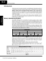
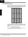
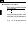
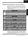
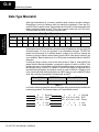
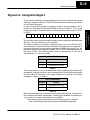
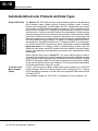
Numbering Systems
1G
In This Appendix. . . .
— Introduction
— Binary Numbering System
— Hexadecimal Numbering System
— Octal Numbering System
— Binary Coded Decimal (BCD) Numbering System
— Real (Floating Point) Numbering System
— BCD/Binary/Decimal/Hex/Octal -- What is the Difference?
— Data Type Mismatch
— Signed vs. Unsigned Integers
— AutomationDirect.com Products and Data Types
G--2
Numbering Systems
Appendix G
Numbering Systems
Introduction
As almost anyone who uses a computer is somewhat aware, the actual operations of
a computer are done with a binary number system. Traditionally, the two possible
states for a binary system are represented by the digits for ”zero” (0) and ”one” (1)
although ”off” and ”on” or sometimes ”no” and yes” are closer to what is actually
involved. Most of the time a typical PC user has no need to think about this aspect of
computers, but every now and then one gets confronted with the underlying nature
of the binary system.
A PLC user should be more aware of the binary system specifically the PLC
programmer. This appendix will provide an explanation of the numbering systems
most commonly used by a PLC.
Binary Numbering System
Computers, including PLCs, use the Base 2 numbering system, which is called
Binary or Boolean. Like in a computer there are only two valid digits in Base 2 a PLC
relies on, zero and one, or off and on respectively. You would think that it would be
hard to have a numbering system built on Base 2 with only two possible values, but
the secret is by encoding using several digits.
Each digit in the base 2 system when referenced by a computer is called a bit. When
four bits are grouped together, they form what is known as a nibble. Eight bits or two
nibbles would be a byte. Sixteen bits or two bytes would be a word as in. Thirty--two
bits or two words is a double word as in Table 1.
Double Word
Word
Byte
Nibble
Nibble
Word
Byte
Nibble
Byte
Nibble
Nibble
Nibble
Byte
Nibble
Nibble
0 0 0 0 0 0 0 0 0 0 0 0 0 0 0 0 0 0 0 0 0 0 0 0 0 0 0 0 0 0 0 0
Table 1
Binary is not “natural“ for us to use since we have grown up using the base 10
system. Base 10 uses the numbers 0--9, as we are all well aware. From now on, the
different bases will be shown as a subscripted number following the number.
Example: 10 decimal would be 1010.
Table 2 shows how base 2 numbers relate to their decimal equivalents.
A nibble of 10012 would be equal to a decimal number 9 (1*23 + 1*20 or 810 + 110). A
byte of 110101012 would be equal to 213 (1*27 + 1*26 +1*24 + 1*22 +1*20 or 12810 +
6410 + 1610 + 410 + 110).
Table 2
DL105 PLC User Manual, 3rd Edition
Numbering Systems
G--3
Hexadecimal Numbering System
The binary numbering system can be difficult and cumbersome to interpret for some
users. Therefore, the hexadecimal numbering system was developed as a
convenience for humans since the PLC (computer) only understands pure binary.
The hexadecimal system is useful because it can represent every byte (8 bits) as two
consecutive hexadecimal digits. It is easier for us to read hexadecimal numbers than
binary numbers.
Decimal Hex
Decimal Hex
0
0
9
9
1
1
10
A
2
2
11
B
3
3
12
C
4
4
13
D
5
5
14
E
6
6
15
F
7
7
16
10
8
8
17
11
Table 3
Note that “10” and “11“ in hex are not the same as “10“ and “11“ in decimal. Only the
first ten numbers 0--9 are the same in the two representations. For example,
consider the hex number “D8AF“. To evaluate this hex number use the same method
used to write decimal numbers. Each digit in a decimal number represents a multiple
of a power of ten (base 10). Powers of ten increase from right to left. For example, the
decimal number 365 means 3x10² + 6x10 + 5. In hex each digit represents a multiple
of a power of sixteen (base 16). Therefore, the hex number D8AF translated to
decimal means 13x163 + 8x162 + 10x16 + 15 = 55471. However, going through the
arithmetic for hex numbers in order to evaluate them is not really necessary. The
easier way is to use the calculator that comes as an accessory in Windows. It can
convert between decimal and hex when in “Scientific“ view.
Note that a hex number such as “365“ is not the same as the decimal number “365“.
Its actual value in decimal terms is 3x162 6x16 + 5 = 869. To avoid confusion, hex
numbers are often labeled or tagged so that their meaning is clear. One method of
tagging hex numbers is to append a lower case “h“ at the end. Another method of
labeling is to precede the number with 0x. Thus, the hex number “D8AF“ can also be
written “D8AFh“, where the lower case “h” at the end is just a label to make sure we
know that it is a hex number. Also, D8AF can be written with a labeling prefix as
“0xD8AF”.
DL105 PLC User Manual, 3rd Edition
Appendix G
Numbering Systems
The hexadecimal numbering system uses 16 characters (base 16) to represent
values. The first ten characters are the same as our decimal system, 0--9, and the
first six letters of the alphabet, A--F. Table 3 lists the first eighteen decimal numbers;
0--17 in the left column and the equivalent hexadecimal numbers are shown in the
right column.
G--4
Numbering Systems
Octal Numbering System
Appendix G
Numbering Systems
Many of the early computers used the octal numbering system for compiled
printouts. Today, the PLC is about the only device that uses the Octal numbering
system. The octal numbering system uses 8 values to represent numbers. The
values are 0--7 being Base 8. Table 4 shows the first 32 decimal digits in octal. Note
that the octal values are 0--7, 10--17, 20--27, and 30--37.
Octal
Decimal
Octal
Decimal
0
0
20
16
1
1
21
17
2
2
22
18
3
3
23
19
4
4
24
20
5
5
25
21
6
6
26
22
7
7
27
23
10
8
30
24
11
9
31
25
12
10
32
26
13
11
33
27
14
12
34
28
15
13
35
29
16
14
36
30
17
15
37
31
Table 4
This follows the DirectLOGIC PLCs. Refer to the bit maps in Chapter 4 and notice
that the memory addresses are numbered in octal, as well as each bit. The octal
system is much like counting in the decimal system without the digits 8 and 9 being
available.
The general format for four digits of the octal number is:
(d x 80) + (d x 81) + (d x 82) + (d x 83)
where “d“ means digit. This is the same format used in the binary, decimal, or
hexadecimal systems except that the base number for octal is 8.
DL105 PLC User Manual, 3rd Edition
G--5
Numbering Systems
Using the powers of expansion, the example below shows octal 4730 converted to
decimal.
Appendix G
Numbering Systems
Binary Coded Decimal (BCD) Numbering System
BCD is a numbering system where four bits are used to represent each decimal digit.
The binary codes corresponding to the hexadecimal digits A--F are not used in the
BCD system. For this reason numbers cannot be coded as efficiently using the BCD
system. For example, a byte can represent a maximum of 256 different numbers (i.e.
0--255) using normal binary, whereas only 100 distinct numbers (i.e. 0--99) could be
coded using BCD. Also, note that BCD is a subset of hexadecimal and neither one
does negative numbers.
BCD Bit Pattern
Bit #
15 14 13 12 11 10
103
Power
Bit Value
Max Value
8
4
2
9
9
8
7
102
1
8
4
2
9
6
5
4
3
101
1
8
4
2
9
2
1
0
100
1
8
4
2
1
9
Table 5
One plus for BCD is that it reads like a decimal number, whereas 867 in BCD would
mean 867 decimal. No conversion is needed.
DL105 PLC User Manual, 3rd Edition
G--6
Numbering Systems
Real (Floating Point) Numbering System
The terms Real and floating--point both describe IEEE--754 floating point arithmetic.
This standard specifies how single precision (32 bit) and double precision (64 bit)
floating point numbers are to be represented as well as how arithmetic should be
carried out on them. Most PLCs use the 32--bit format for floating point (or Real)
numbers which will be discussed here.
Appendix G
Numbering Systems
Real (Floating Point 32) Bit Pattern
Bit #
31
Sign
Bit #
15
30 29 28 27 26 25 24 23 22 21 20 19 18 17 16
Exponent
14 13 12 11 10
Mantissa
9
8
7
6
5
4
3
2
1
0
Mantissa (continues from above)
Table 6
Floating point numbers, which DirectLOGIC PLCs use, have three basic
components: sign, exponent and mantissa. The 32 bit word required for the IEEE
standard floating point numbers is shown in Table 6. It is represented as a number
bits from 0 to 31, left to right. The first bit (31) is the sign bit, the next eight bits (30--23)
are the exponent bits and the final 23 bits (22--0) are the fraction bits. In summary:
The sign bit is either “0” for positive or “1“ for negative;
The exponent uses base 2;
The first bit of the mantissa is typically assumed to be “1.fff“, where “f“ is the field of
fraction bits.
The Internet can provide a more in--depth explanation of the floating point
numbering system. One website to look at is:
http://www.psc.edu/general/software/packages/ieee/ieee.php
DL105 PLC User Manual, 3rd Edition
G--7
Numbering Systems
BCD/Binary/Decimal/Hex/Octal -- What is the Difference?
Sometimes there is confusion about the differences between the data types used in
DirectLOGIC PLCs. The PLC’s native data format is BCD, while the I/O numbering
system is octal. Other numbering formats used are binary, decimal and Real.
Although data is stored in the same manner (0’s and 1’s), there are differences in the
way that the PLC interprets it.
While all of the formats rely in the base 2 numbering system and bit--coded data, the
format of the data is dissimilar. The formats discussed are shown in Table 7 below.
Bit #
Decimal
Bit Value
15
14
13
12
11
10
9
8
7
3
2
6
7
8
1
6
3
8
4
8
1
9
2
4
0
9
6
2
0
4
8
1
0
2
4
5
1
2
2
5
6
1
Max Value
2
8
6
5
4
3
2
1
0
6
4
3
2
1
6
8
4
2
1
65535
Hexidecimal Bit Pattern
Bit #
15
14
13
12
11
10
9
8
7
6
5
4
3
2
1
0
Decimal
Bit Value
8
4
2
1
8
4
2
1
8
4
2
1
8
4
2
1
Max Value
F
F
F
F
BCD Bit Pattern
Bit #
15
14
13
12
11
10
9
8
7
6
5
4
3
2
1
0
Decimal
Bit Value
8
4
2
1
8
4
2
1
8
4
2
1
8
4
2
1
Max Value
9
9
9
9
Octal Bit Pattern
Bit #
15
14
13
12
11
10
9
8
7
6
5
4
3
2
1
0
Bit Value
1
4
2
1
4
2
1
4
2
1
4
2
1
4
2
1
Max Value
1
7
7
7
7
7
Octal Bit Pattern
Bit #
31
30
29
28
15
26
25
24
23
22
21
20
Exponent
Sign
Bit #
27
14
13
12
11
10
19
18
17
16
1
0
Mantissa
9
8
7
6
5
4
3
2
Mantissa (continued from above)
Table 7
As seen in Table 7, the BCD and hexadecimal formats are similar, although the
maximum number for each grouping is different (9 for BCD and F for hexadecimal).
This allows both formats to use the same display method. The unfortunate side
effect is that unless the data type is documented, it’s difficult to know what the data
type is unless it contains the letters A--F.
DL105 PLC User Manual, 3rd Edition
Appendix G
Numbering Systems
Binary/Decimal Bit Pattern
G--8
Numbering Systems
Data Type Mismatch
Data type mismatching is a common problem when using an operator interface.
Diagnosing it can be a challenge until you identify the symptoms. Since the PLC
uses BCD as the native format, many people tend to think it is interchangeable with
binary (unsigned integer) format. This is true to some extent, but not in this case.
Table 8 shows how BCD and binary numbers differ.
Appendix G
Numbering Systems
Data Type Mismatch
Decimal
0
1
2
3
4
5
6
7
8
9
10
11
BCD
0000 0001 0010 0011 0100 0101 0110 0111 1000 1001 0001 0000 0001 0001
Binary
0000 0001 0010 0011 0100 0101 0110 0111 1000 1001 0000 1010 0000 1011
Table 8
As the table shows, BCD and binary share the same bit pattern up until you get to the
decimal number 10. Once you get past 10, the bit pattern changes. The BCD bit
pattern for the decimal 10 is actually equal to a value of 16 in binary, causing the
number to jump six digits by when viewing it as the BCD. With larger numbers, the
error multiplies. Binary values from 10 to 15 Decimal are actually invalid for the BCD
data type.
Looking at a larger number, such as the value shown in Table 9, both the BCD bit
pattern and the decimal bit pattern correspond to a base 10 value of 409510. If bit
patterns are read, or interpreted, in a different format than what is used to write them,
the data will not be correct. For instance, if the BCD bit pattern is interpreted as a
decimal (binary) bit pattern, the result is a base 10 value of 1653310. Similarly, if you
try to view the decimal (binary) bit pattern as a BCD value, it is not a valid BCD value
at all, but could be represented in hexadecimal as 0xFFF.
Base 10 Value
BCD Bit Pattern
Binary Bit Pattern
4095
0100 0000 1001 0101
1111 1111 1111
Table 9
Look at the following examples and note the same value represented by the different
numbering systems. The decimal values of 67 and 4660 are used.
6
7 Decimal
0110 0111 BCD
0100 0011 Binary
4
3 Hex
1
0 3 Octal
DL105 PLC User Manual, 3rd Edition
4
6
6
0 Decimal
0100 0110 0110 0000 BCD
0001 0010 0011 0100 Binary
1
2
3
4 Hex
1
1
0
6
4 Octal
G--9
Numbering Systems
Signed vs. Unsigned Integers
Bit # 15 14 13 12 11 10
9
8
7
6
5
4
3
2
1
0
Table 10
There are two ways to encode a negative number: two’s complement and Magnitude
Plus sign. The two methods are not compatible.
The simplest method to represent a negative number is to use one bit of the PLC
word as the sign of a number while the remainder of the word gives its magnitude. It
is general convention to use the most significant bit (MSB) as the sign bit: a 1 will
indicate a negative, and a 0 a positive number. Thus, a 16 bit word allows numbers in
the range ¦32767. The following tables show a representation of 100 and a
representation of --100 in this format.
Magnitude Plus Sign
Decimal
Binary
100
0000 0000 0110 0100
--100
1000 0000 0110 0100
Table 11
Two’s complement is a bit more complicated. Without getting involved with a full
explanation, a simple formula for two’s complement is to invert the binary and add
one (see Table 12). Basically, 1’s are being changed to 0’s and all 0’s are being
changed to 1, then a 1 is added.
Two’s Compliment
Decimal
Binary
100
0000 0000 0110 0100
--100
1111 1111 1001 1100
Table 12
More information about 2’s complement can be found on the Internet, however most
of the websites deal with 8--bit examples. Two fairly good websites are listed below,
you can also do a search and checkout more websites.
http://www.evergreen.edu/biophysics/technotes/program/2s_comp.htm
http://www.website.masmforum.com/tutorials/fptute/fpuchap2.htm
DL105 PLC User Manual, 3rd Edition
Appendix G
Numbering Systems
So far, we have dealt with unsigned data types only. Now we will deal with signed
data types (negative numbers). The BCD and hexadecimal numbering systems do
not use signed data types.
In order to signify that a number is negative or positive, we must assign a bit to it.
Usually, this is the Most Significant Bit (MSB) as shown in Table 10. For a 16--bit
number, this is bit 15. This means that for 16--bit numbers we have a range of --32767
to 32767.
G--10
Numbering Systems
AutomationDirect.com Products and Data Types
Appendix G
Numbering Systems
DirectLOGIC PLCs
C--more/C--more
Micro--Graphic
Panels
The DirectLOGIC PLC family uses the octal numbering system for all addressing
which includes: inputs, outputs, internal V--memory locations, timers, counters,
internal control relays (bits), etc. Most data in the PLC, including timer and counter
current values, is in BCD format by default. User data in V--memory locations may be
stored in other data types if it is changed by the programmer, or comes from some
external source, such as an operator interface. Any manipulation of data must use
instructions appropriate for that data type which includes: Load instructions, Math
instructions, Out box instructions, comparison instructions, etc. In many cases, the
data can be changed from one data type to another, but be aware of the limitations of
the various data types when doing so. For example, to change a value from BCD to
decimal (binary), use a BIN instruction box. To change from BCD to a real number,
use a BIN and a BTOR instruction box. When using Math instructions, the data
types must match. For example, a BCD or decimal (binary) number cannot be
added to a real number, and a BCD number cannot be added to a decimal (binary)
number. If the data types are mismatched, the results of any math operation will be
meaningless.
When using the Data View in DirectSOFT, be certain that the proper format is
selected for the element to be viewed. The data type and length is selected using the
drop--down boxes at the top of the Data View window. Also notice that BCD is called
BCD/Hex. Remember that BCD is a subset of hexadecimal so they share a display
format even though the values may be different. This is where good documentation
of the data type stored in memory is crucial.
In the C--more and C--more Micro--Graphic HMI operator panels, the 16--bit BCD
format is listed as “BCD int 16“. Binary format is either “Unsigned int 16“ or “Signed
int 16“ depending on whether or not the value can be negative. Real number format
is “Floating PT 32”.
More available formats are, “BCD int 32“, “Unsigned int 32“ and “Signed int 32“.
DL105 PLC User Manual, 3rd Edition