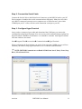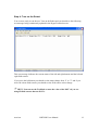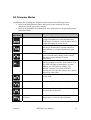
1
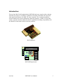
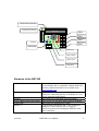
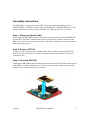
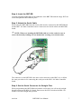
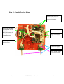
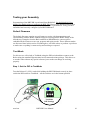
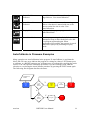
muvium
RBT-DB
RoboTech Daughterboard
User’s Guide
Version 0.1, 9 October 2007
muvium
RBT-DB Users Manual
1
RBT-DB.............................................................................................................................. 1
RoboTech Daughterboard................................................................................................... 1
User’s Guide ....................................................................................................................... 1
Introduction......................................................................................................................... 3
Elements of the RBT-DB................................................................................................ 4
RBT-DB Functional Description .................................................................................... 5
Motor Control Drivers ................................................................................................ 5
6 Analog Inputs........................................................................................................... 5
4 Digital Inputs ........................................................................................................... 5
I2C EEPROM DataStore ............................................................................................ 5
Speaker........................................................................................................................ 5
Status LEDS................................................................................................................ 5
4-Way DIP Switch ...................................................................................................... 5
Assembly Instructions......................................................................................................... 6
Step 1: Disconnect Serial Cable.................................................................................. 6
Step 2: Remove JRT-101 ............................................................................................ 6
Step 3: Orientate RBT-DB.......................................................................................... 6
Step 4: Insert the RBT-DB.......................................................................................... 7
Step 5: Attach the Serial Cable ................................................................................... 7
Step 6: Set the Serial Connector for Straight-Thru..................................................... 7
Step 7: Connect Touch Sensors .................................................................................. 8
Step 8: Connect Field Sensors .................................................................................... 8
Step 9: Verify Jumper Settings ................................................................................... 8
Step 10: Verify Motor Wiring Connections................................................................ 8
Step 11: Visually Confirm Setup ................................................................................ 9
Testing your Assembly ..................................................................................................... 10
Default Firmware .......................................................................................................... 10
Test Mode ..................................................................................................................... 10
Step 1: Set the DIP to TestMode............................................................................... 10
Step 2: Connect the Serial Cable .............................................................................. 11
Step 3: Configure HyperTerminal ............................................................................ 11
Step 4: Turn on the Robot......................................................................................... 12
All Firmware Modes ......................................................................................................... 13
AutoCalibrate in Firmware Examples .............................................................................. 14
Schematic.......................................................................................................................... 16
muvium
RBT-DB Users Manual
2
Introduction
The muvium RoboTech Daughterboard ( RBT-DB) has been created to allow students
and other developers to extend the capabilities of the RoboTech RDS-X01 robot and
other applications that use the RDC-101 base controller. The extended capabilities
include enhanced IO with an additional 4 Digital IO channels, 4 LEDS, a 4 Way DIP
switch, a Speaker and also enhanced software capabilities including compatibility with
the RoboPAL educational robotics software platform.
RBT-DB Photo
uVM-2620
ON
DIP
1 2 3 4
RBT-DB Diagrammatic
muvium
RBT-DB Users Manual
3
Muvium Microcontroller
Serial Port Connector
uVM-2620
DIO0
DIO1
DIO2
Speaker
ON
4-Way DIP
DIO3
DIP
1 2 3 4
LED (Red)
LED (Yellow)
LED (Green)
LED (Blue)
Elements of the RBT-DB
Muvium Microcontroller
The muvium microcontroller is a java enabled
microcontroller that is compatible with the RoboPAL
software platform and other tools available from
www.muvium.com
Serial Port Connector
The SerialPort Connector is a 6-PIN JSR socket
suitable for connecting directly to the RDR-301 232C
Serial Communications Board
Speaker
Mini Speaker for generating tones and sounds
LEDS ( Blue,Green,Yellow,Red) Status LEDS for indicating status and user feedback
4-Way DIP
DIP Switch for generating user input
DIO(0..3)
4 Digital Input and Output JSR 3-Way connectors
suitable for connecting directly to a range of
RoboTech connectors including the RDI-801 touch
sensor and others.
muvium
RBT-DB Users Manual
4
RBT-DB Functional Description
Referring to the Schematic in the Appendix the RBT-DB has the following functionality
when combined with the RDC-101 board.
Motor Control Drivers
Generates two motor control driver signals on the M1 and M2 pin pairs. This is a HBridge motor control signal which drives the H-Bridge controller on the RDC-101B
which in turn generate the power signals to drive the DC motors of the robot.
6 Analog Inputs
6 Analog inputs are available reading from the CN1 to CN6 Input connectors on the
RDC-101 board. These are read with a 10-bit accuracy.
4 Digital Inputs
4 Digital inputs are available, DIO1 to DIO4, from the RBT-DB board connectors. DIO1
and DIO2 also offer interrupt detection change detection for rapid response to events
such as touching objects.
I2C EEPROM DataStore
The I2C EEPROM on the RDC-101 is readable and writeable allowing serialized
programs or data to be stored and retrieved
Speaker
The speaker can be used to generate sounds and tones
Status LEDS
Four status LEDS, Blue, Green, Yellow and Red are used to generate status and user
feedback signals during program execution.
4-Way DIP Switch
A 4-Way Dip Switch is multiplexed with the status LEDS to allow for further user Input.
This is typically used for program and mode selections.
muvium
RBT-DB Users Manual
5
Assembly Instructions
The RBT-DB is a replacement for the JRT-101 microcontroller that ships with the
RoboTech RDC-101 Main Controller board. The underside of the RBT-DB has a 16 pin
header which inserts into the socket of the JRT-101 when the JRT-101 is removed.
Step 1: Disconnect Serial Cable
When using the RBT-DB board, the serial cable must be connected to the RBT-DB and
not the RDC-101 Main Controller board. If the serial cable is already connected to the
RDC-101 it must first be disconnected. The serial cable will then be reconnected with the
RBT-DB board in Step 5.
Step 2: Remove JRT-101
Using a IC Chip removal tool or carefully with a flat screwdriver remove the JRT-101
from it’s socket on the RDC-101 Main Controller board and store the JRT-101 device
somewhere safe.
Step 3: Orientate RBT-DB
Orientate the RBT-DB board such that the notch on the board faces the left bottom corner
of the RDC-101 Main Controller board. There is a tall capacitor in this corner that this
notch avoids which can be used as a reference.
muvium
RBT-DB Users Manual
6
Step 4: Insert the RBT-DB
Carefully align the header pins on the underside of the RBT-DB with the empty JRT-101
socket and push the RBT-DB into place.
Step 5: Attach the Serial Cable
When using the RBT-DB board, the serial cable must be connected to the RBT-DB and
not the RDC-101 Main Controller board. Connect now the Serial cable to the RBT-DB
board.
1 NOTE: When ever handing the RBT-DB while it is in the socket be sure to
secure the board by holding it in one hand while working on it with the other.
The connector on the RBT-DB is the same as the connector on the RDC-101 so follow
the same procedure as for connecting the serial port to the RDC-101 Main Controller
board.
Step 6: Set the Serial Connector for Straight-Thru
When programming the RBT-DB board with the serial cable you will use the straight
through setting on the RD1-301 board. Ensure now the SW1 switch on the RD1-301
board is set to the straight-thru position.
muvium
RBT-DB Users Manual
7
Step 7: Connect Touch Sensors
Connect the two touch sensors. Connect the Left Touch Sensor to the DIO0 socket and
connect the Right Touch Sensor to the DIO1 socket.
Step 8: Connect Field Sensors
The field sensors are connected to the Analog input sensors CN1 and CN2. Connect the
Left Field Sensor to CN1 and connect the Right Field Sensor to CN2.
Step 9: Verify Jumper Settings
Verify the jumper settings on the RDC-101 are as follows
•
•
•
•
•
•
•
J1 = Jumper B
J2 = Jumper A
J3 = Jumper A
J4 = Jumper B
J5 = Jumper A
SW2 = ‘R’ Position
SW4 = ON Position
Step 10: Verify Motor Wiring Connections
The RBT-DB drives the motors where M1 is the right motor and M2 is the left motor.
Depending on which side the motors are physically connected will determine which wires
need to connect to which pins.
If your motors are connected with the motor with the yellow and orange wires on the
right hand side of the robot, then for correct directional control connect the motor wires
as follows.
•
•
•
•
M1+ connects to the yellow wire
M1- connects to the orange wire
M2+ connects to the green wire
M2- connects to the blue wire
If your motors are connected with the motor with the yellow and orange wires on the left
hand side of the robot, then for correct directional control connect the motor wires as
follows.
•
•
•
•
M1+ connects to the green wire
M1- connects to the blue wire
M2+ connects to the yellow wire
M2- connects to the orange wire
muvium
RBT-DB Users Manual
8
Step 11: Visually Confirm Setup
Ensure motor wires are
connected with the
correct orientation.
When using the RBTDB board the Serial
Cable Connects to the
RBT-DB instead of
the RDC-101 Main
Controller board
Left Field Sensor
Connects to CN1
Right Field Sensor
Connects to CN1
Serial Port is set for
Straight-Thru
Left Touch Sensor
Connects to DIO0
Right Touch Sensor
Connects to DIO1
muvium
RBT-DB Users Manual
9
Testing your Assembly
Programming of the RBT-DB is performed from RoboPAL. See the RoboPAL User
Manual for details on how to program the RBT-DB. However the default firmware that
ships with the RBT-DB allows you to perform several experiments to verify you have
assembled and correctly configured your RBT-DB board.
Default Firmware
The default firmware contains several features to assist with demonstrations and
experimenting with the Robot without having to first program the Robot. Many of the
introductory examples from the Basic and Rescue RoboDidactics coursework are
embedded in the firmware as are test, program and replay modes. These different modes
are discussed later in this section. First though we will look at how to perform a quick test
to make sure everything is connected up and working as expected.
Test Mode
For this test we will switch to TestMode using the DIP switch and then connect to the
Robot using the standard Hyperterminal serial communications package. This allows us
to test the robot without any special software just to make sure things are working
properly.
Step 1: Set the DIP to TestMode
Turn the Robot off ( SW1 ) and while holding the RBT-DB board securely in place
switch the DIP switch to TestMode – All the switches are in the bottom position
TestMode
DIP Settings
muvium
RBT-DB Users Manual
10
Step 2: Connect the Serial Cable
Connect the Serial Cable to the Robot Serial Connector on the RDI-301 and to your PC.
Each computer is handler their serial communications differently. Many have the older
style RS232 connector but many newer computers use a USB converter. Also which
COMM port you PC will use for the serial connection is unique to your PC.
Step 3: Configure HyperTerminal
Once you have connected your cable and determined the COM port you can test the
configuration using HyperTerminal. You can use any serial communications package but
HyperTerminal is bundled with Windows so it should be available. Start HyperTerminal
from the windows start menu
StartÎProgram FilesÎAccesseriesÎCommunicationsÎHyperTerminal
When configuring the Port Settings you need to first select the COMM port you will use
and then you need to setup HyperTerminal to use 115200N8 communications.
1 NOTE: RBT-DB Communicates at Baud 115200, Data bits 8, Parity None, Stop
Bits 1, FlowControl None
muvium
RBT-DB Users Manual
11
Step 4: Turn on the Robot
You are now ready to run the test. Turn on the Robot and you should see the following
test message being continuously updated in the HyperTerminal screen.
This test message indicates the current status of the left and right buttons and the left and
right field sensors.
If you press the left button you should see the status change from ‘F’ to ‘T’ and if you
move the robots field sensors you should see the field sensor values change.
1 HINT: You can use the TestMode to tune the value of the POT’s if you are
using IR field sensors that use POT’s.
muvium
RBT-DB Users Manual
12
All Firmware Modes
In addition to the TestMode the default firmware supports the following modes.
• Refer to the RoboDidactics Basic and Rescue course materials for more
information on the pre-stored examples.
• Refer to the RoboPAL User Manual for more information on programming using
Immediate Mode.
DIP
SETTING
MODE
Mode Description
Test Mode
Prints sensor information to UART – Connect
to HyperTerminal to see current Button and
Field Values. Useful for verify assembly and for
testing and tuning the sensor levels.
Executes the Drive Forward Basic Example.
This drives forward for 4 seconds and has no
AutoCalibrate so it begins immediately upon
reset.
Execute the Drive until Change Basic Example.
Drives forward until a change of the sensors.
This has no AutoCalibrate so begins
immediately.
Executes the AutoCalibrate Circle Example.
The first example to use the AutoCalibrate. The
blue LED will light up indicating it is ready.
‘PRESS’ the left button to calibrate. The
‘RIGHT’ button to run. Once calibrated
pressing run will cause the robot to drive ahead
and stop at a black line.
Executes the clear the circle example. Requires
a circle field.
1 - Drive Forward
2 – Drive until Change
3 – AutoCalibrate Circle
4- Clear Circle
5- Auto calibrate Rescue Attempts to calibrate 3 colors or GreyScale.
muvium
6 – Clear Rescue
Attempts to calibrate 3 colors or GreyScale and
then clear the rescue field.
1 – A First Line
Follower
The first line follower drives the robot in a
roughs square. It has no AutoCalibration
RBT-DB Users Manual
13
2 - A Real Line
Follower
A real line follower follows a line edge with a
edge follower. Uses AutoCalibration.
3 – A Faster Line
Follower
Uses two sensors. Make sure when starting to
follow a line that it is started with one of the
sensors on the line else it waits. Uses
AutoCalibration.
Replays the last program programmed in
Immediate Mode
Replay Mode
Immediate Mode
Enables programming from RoboPAL.
Attempts to loop to allow RoboPAL to be able
to reprogram again and again. When
programmed successfully the program is stored
and can be replayed by switching to replay
mode..
AutoCalibrate in Firmware Examples
Many examples use AutoCalibration in the program. If AutoCalibrate is used then the
blue LED will come on to indicate the program is waiting for either a LEFT button press
to calibrate, or a RIGHT button to run. A Button press is performed by touching the touch
sensors. You can repeat the calibration procedure if you are not happy with what the
robot drove over during the AutoCalibrate procedure by pressing the LEFT button again.
The following flow diagram describes the states.
POWER ON |
RESET
Left
Button
Pressed
Blue
LED
ON
Y
Yellow
LED
ON
Do
Calibrate
Run
Program
END
RED
LED
ON
N
N
muvium
Right
Button
Pressed
Y
RBT-DB Users Manual
14
The calibration information is stored in an EEPROM so you don’t need to calibrate each
time you run a program. Note however that as the battery charge level changes so may
the sensor value results hence AutoCalibration makes it easy to compensate for the
changing ranges of the sensors due to battery level changes.
muvium
RBT-DB Users Manual
15
Schematic
muvium
RBT-DB Users Manual
16