1
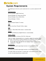
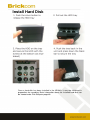
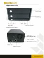
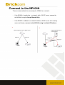
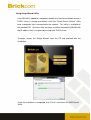
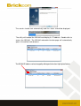
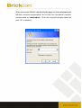
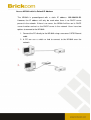
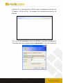
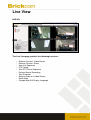
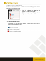
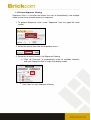
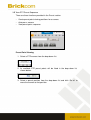
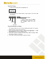
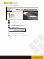
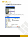
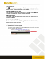
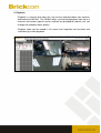
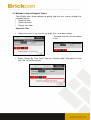
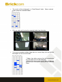
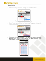
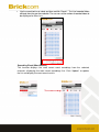
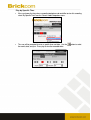
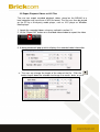
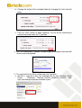
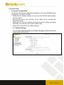
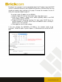
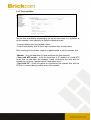
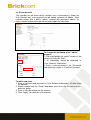
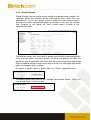
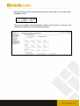
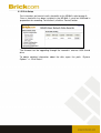
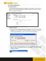
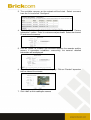
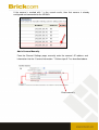
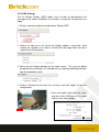
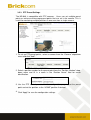
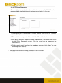
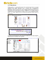
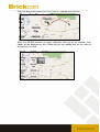
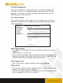
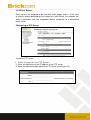
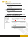
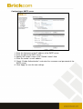
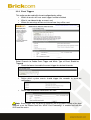
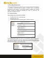
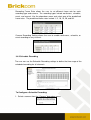
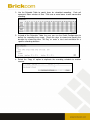
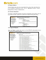
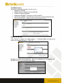
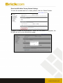
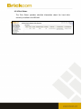
Network Video Recorder
NR-04A
User’s Manual
Quality Service Group
Product name:
Network Video Recorder (NR-04A)
Release Date:
2010/07
Manual Revision:
V1.00
Web site:
www.brickcom.com
Email:
[email protected]
[email protected]
©2010 Brickcom Corporation. All Rights Reserved
Before You Use This Product
When you first open the product’s package, verify that all the accessories listed on the
“Package Contents” are included. Before installing the NR-04A, read the warnings in the
“Quick Installation Guide” to avoid misuse. When installing the NR-04A, carefully read
and follow the instructions in the “Installation” chapters to avoid damages due to faulty
assembly or installation.
Package Contents
NR-04A Network Video Recorder
Power Adapter ( Input 100-240V, Output +12V/4A )
Ethernet Cable
Printed Quick Installation Guide
Printed Warranty Card
CD-ROM ( Quick Installation Guide, User’s Manual, Setup Wizard )
Network Video Recorder Overview
The Brickcom NR-04A Network Video Recorder (NVR) is an ARM9-based recording
solution for SMB and SOHO users to effectively grow and navigate their network
surveillance systems. This NVR is equipped with an embedded Linux operating
system to allow users to remotely monitor, record, and view live video feed from up
to 4 Brickcom network cameras. With the support of megapixel resolution and
H.264 compression, it uses less bandwidth while offering the optimal recording
quality and image viewing.
Easy installment and management is central to the operation of the NR-04A. For
easy set up and scalability, the NVR is able to automatically search and access the
available cameras on the network. Operation of the IP cameras and NVR is
managed through Brickcom’s EasyConfig software and GUI. A maximum of four
PCs are able to concurrently access the NVR and view live or recorded video feed
using Microsoft Internet Explorer and the Brickcom GUI.
The NR-04A is designed for long-term recording and video storage with a Gigabit
Ethernet port and two SATA hard disks with a maximum capacity of 3 terabytes.
Flexible recording options include manual, event-triggered, scheduled or continuous.
With the help of the Brickcom NR-04A and its IP cameras, users can quickly and
easily build a secure IP surveillance system.
System Requirements
The following are minimum system requirements for a system to operate the NR04A:
Operating System
Microsoft Windows 2000 Professional
Microsoft Windows XP Professional (32 bit)
Microsoft Windows Server 2003 (32 bit)
Microsoft Windows 7 (32 bit)
Browser
Microsoft Internet Explorer 7 or above
CPU
Minimum Intel Core 2 Duo @ 2.4GHz or higher
RAM
Minimum 1 GB of RAM, 2GB or above is recommended
Network
Minimum 10/100 Ethernet (Gigabit Ethernet is recommended)
Graphics Adapter
AGP or PCI-Express, minimum 1024×768, 16 bit colors.
*Note: It is highly recommended to use a graphics adaptor that provides higher
than 1024 x 768 resolution in order to experience the full benefits of the software.
Make sure the display DPI setting is set to the default at 96DPI
To set DPI value, right-click on the desktop, choose “Settings” tab >>
“Advanced” >> “General”
CD-ROM Drive:
It is necessary to read the operating instructions in the provided CD-ROM.
Adobe Reader:
It is necessary to read the operating instructions in the provided CD-ROM.
The audio function will not work if a sound card is not installed in the PC. Audio
may be interrupted depending on network traffic.
Install Hard Disk
Once a hard disk has been installed in the NR-04A, it must be initialized in
preparation for recording. Basic information about the installed hard disk can
be viewed under Disk Setup on page 40.
Hardware Illustration (Front)
Hardware Illustration (Rear)
Connect to the NR-04A
There are two methods for connecting the NR-04A to a network:
•
If the NR-04A is added to a network with a DHCP server, connect to
the NR-04A using the Setup Wizard Utility
•
If the NR-04A is added to a network without a DHCP server or it is being
accessed directly, connect to the NR-04A using its default IP Address
Using Setup Wizard Utility
If the NR-04A is added to a corporate network or a local area network where a
DHCP server is already presented, install the “Smart Device Search” utility
onto a computer that is connected to the network. This utility is available on
the provided CD. Once the utility has been installed, located the NR-04A with
the IP address that is assigned by the top-level DHCP server.
To begin, launch the “Setup Wizard” from the CD and proceed with the
installation.
Once the installation is completed, click “Finish” and launch the NVR Search
Utility.
The search should start automatically and the status should be displayed.
The utility will located the NR-04A and display its IP address. Double-click to
access the NR-04A. The NR-04A web administration page will automatically
open in the default web browser.
The NR-04A IP address can be changed by clicking on the button highlighted below.
The user will be prompted to enter the NR-04A login information before being
allowed to change the device’s IP address. The default username and
password is admin/admin.
To search again for the NR-04A, click on the button highlighted below. To access the NR04A’s web administration page, double-click on any of the search results.
Perform search again
Access NR-04A web administration page
When accessing the NR-04A’s web administration page, user will be prompted for the
NR-04A username and password. For first time use, the default username
and password are admin/admin. Enter the username and password and
click “OK” to continue.
Access NR-04A with its Default IP Address
The NR-04A is preconfigured with a static IP address: 192.168.101.50.
However, the IP address will only be used when there is no DHCP server
present in the network. If there is no server, the NR-04A will turn on its DHCP
server function and act as the DHCP server in the network. Users have two
options to connect to the NR-04A:
1. Connect the PC directly to the NR-04A using a crossover CAT5 Ethernet
cable
2. A PC can use a switch or hub to connect to the NR-04A over the
network
Once the PC is connected to the NR-04A, open a web browser and enter the
IP address: 192.168.101.50. The computer will automatically connect to the
NR-04A.
The user will be prompted to enter the NR-04A’s username and password.
The default username and password are admin/admin. Click “OK” to continue.
Live View
NVR4Ch
The Live View page provides the following functions:
•
•
•
•
•
•
•
•
•
•
Retrieve Camera’s Video Stream
Retrieve Camera’s Status
View Live Sequence
PTZ Control
View PTZ Preset Sequence
Perform Manual Recording
Take Snapshot
Receive Audio of a Video Stream
Send Audio
Change Web GUI Display Language
1.1 Retrieve Camera’s Video Stream
On the Live View page, the list of available cameras will be displayed on the lefthand side of the Live View screen.
•
•
Click “All” to display the video from all
cameras in 4-video display mode
Click on any camera to display video in
single-view display mode
1.2 Retrieve Camera’s Status
The camera list will show each camera’s current status. Each status is
represented with a different color:
Camera is connected
Camera is not connected
Camera is currently recording
1.3 Perform Sequence Viewing
Sequence View is a function that allows the user to automatically view multiple
video streams from selected cameras in sequence.
1. To perform Sequence View, select “Sequence” from the upper-left hand
corner.
2. Select the interval time from the drop-down menu.
3. Select one or more camera(s) for Sequence Viewing.
a. *Click “All Channels” to automatically select all available channels
and start Sequence View in single-view display mode.
4. Click “Start” to start Sequence Viewing
1.4 PTZ Control
PTZ control allows the user to control the pan, tilt, and zoom functions of a
PTZ camera. The user can also adjust the camera’s focus and iris.
The camera(s) which are available for PTZ Control will be displayed in the PTZ
drop-down menu. Select a camera to control the pan, tilt, and zoom functions.
The bar below allows the user to control the pan/tilt speed.
1.5 View PTZ Preset Sequence
There are three functions provided in the Preset section:
•
•
•
Create preset point viewing positions for a camera
Auto-pan a camera
View preset point sequence
Preset Point Viewing
1. Select a PTZ camera from the drop down list:
2. Its available PTZ preset points will be listed in the drop down list
shown below:
3. Select a preset position from the drop-down list and click “Go to” to
move the camera to that position.
Auto Pan Viewing
1. Select a PTZ camera from the drop down list:
2. Use the Auto Pan Control buttons to pan right or left and to stop
the auto pan
Autopan
Pan Left
Stop pan
* Certain cameras do not support
bi-directional pan movements. Use
the “Autopan” button for such
cameras
Pan right
Preset Point Sequence Viewing
This function allows the user to view multiple preset points of a camera
without having to select them one by one.
1. Define the preferred preset points in “Camera Configurations” >> “PTZ
Preset Sequence” under the “Setup” menu.
2. Click “Start” and the recorder will automatically begin to display videos
from the preset points in sequence
3. Click “Stop” to end the preset point sequence viewing.
1.6 Live Video Control Buttons
Take a snapshot of the live view monitor
Turn audio on/off
Start/stop recording of live view
Audio post function
View the Live View in full screen
Display the Live View in its original size
Take a Snapshot of the Live View Monitor
button to take a snapshot of the live video monitor.
1. Click the
2. The snapshot will be displayed in a pop up window:
3. Right-click anywhere on the image and select “Save Image As…” from
the pull-down menu
4. Name the image file and choose which directory the image will be saved
to. Click “Save”.
Turn Audio On/Off
to receive audio from a camera. Click the button once to turn audio on
Click
and the button will change color. The user can only received audio from one
channel at a time. Click the button again to turn audio off.
Start/Stop Recording of Live Video
Users can manually start or stop recording of a live video by using the
The button will change color when the NR-04A is recording
button.
Audio Post Function
This function allows the user to transmit audio through the camera using the
computer microphone.
View the Live View in Full Screen
To view a video in full screen, click the
double-click anywhere on the screen.
button. To exit full screen mode,
1.7 Change Web UI Display Language
The user can change the web GUI display language by selecting the username
link from the upper-right hand corner.
A window will open displaying the user information. The user can select a
language from the Language drop down menu. Click Apply to save the new
settings.
2. Playback
Playback is a function that allows the user to view recorded videos from cameras
attached to the NR-04A. The NR-04A offers synchronized playback from up to 4
channels and various types of search methods are provided to help the user sort
through the recorded videos quickly.
Playback video can be viewed in full screen and snapshots can be taken and
saved during a video playback.
2.1 Methods to Search Playback Videos
The NR-04A offers three methods to quickly help the user search through the
recorded videos:
• Search by time
• Search by event
• Play by start time
Search by Time
•
Select ch a nn e l(s ) to s e a rc h t h rou gh th e re c o rd e d vid e os .
* Selected channels will be marked
in red
• Select “Search By Time Chart” from the “Search mode” drop down list and
click “Go” to start the search.
•
The results will be displayed in a “Date/Channel” table.
in blue represent recorded videos.
Boxes marked
•
Click on a blue cell to view the recorded video from that date.
•
If a camera recorded multiple video clips on a certain day, click on the blue
cell to open an hour/channel table.
* Videos from other cameras that are recorded on
the same date will also be displayed
* Moving the mouse cursor over a blue cell box will
give the user a thumbnail preview of the recorded
video.
Search by Event
•
Select ch a nn e l(s ) to s e a rc h t h rou gh th e re c o rd e d vid e os .
*Selected channels will be marked in red.
•
Select “Search by event” from the “Search mode” drop down list and click
“Go” to start the search.
• The results will be displayed in a list, with the newest recordings
displayed first. Click on a result to view the video recording. Click
“Next Search” to display the next 15 results.
• Use the search tool to set a date and time and click “Search”. The list of recorded videos
will begin from the new time and date. The user can set the number of recorded videos to
be displayed to 30 or less.
Search by Event (Most Recent)
This function displays the most recent event recordings from the selected
channels, displaying the most recent recordings first. Click “Update” to update
the list and display the most recent results.
Play by Specific Time
• If the user knows the time when a recording took place and would like to view this recording,
select “By Specific Time” from the “Search mode” drop-down menu.
• The user will be prompted to enter a specific time and date. Use the
the month, date, and year. Press play to view the recorded video.
button to select
2.2 Export Playback Videos as AVI Files
The user can export recorded playback videos stored on the NR-04A to a
local computer and save them in AVI file format. The files can then be played
on the PC by a third party media player, such as VLC player or Windows
Media player.
1. Locate the recorded videos using any method in section 2.1.
2. Hit the “Export AVI” button on a recorded video window to export the video.
3. A dialog window will pop up which displays the recorded video information.
a. The user can change the length of the video of the file. Click the
button to pull down the calendar to change the month, date, or year.
b. Change the length of the recorded video by changing the start and end
times.
c. Click the “Start” button to begin exporting. The file will be automatically
named and saved under the C: \partition.
4. When the recorded video is exported, a window will pop up notifying the user that the AVI
file was successfully exported.
5. The exported AVI file will be saved under the C partition
a. ffdshow is required to play the exported AVI file with Windows Media
Player.
Download “ffdshow_rev3476_20100615_clsid.exe” from
http://sourceforge.net/projects/ffdshow-tryout/”
3. System Setup
3.1 System Configurations
The System Configurations page provides options to set up the NR-04A quickly
and properly. The options include:
• Configuring the network settings to ensure that the NR-04A works properly
with the network,
• Adjusting the system time and date so that videos will be recorded with
correct timestamp,
• Setting up user accounts and group privileges to prevent settings from being
altered by users other than the system administrator.
• Preparing the hard disk for the video recording.
3.1.1 Network Settings
The user needs to adjust the settings in the Network Setup page in order for the NR-04A
to work properly within the LAN.
By default, the recorder is set to automatically obtain the IP address from the DHCP
server. It should be sufficient in most network environments, and most likely the user
should not need to alter anything in this page. To locate the recorder, use the IP
Utility with steps described in page 12.
To assign a static IP address to the NR-04A:
1. Choose “Static IP” from the “Connection Type” drop-down menu
2. Enter the IP address, subnet mask, default gateway address and DNS
server address for the recorder.
3. Enable the DHCP Server by selecting “On” from under “DHCP Server” to
use the recorder as a DHCP server. Leave it disabled if there is already a
DHCP server in the network.
4. Click Apply to save the new settings.
If the user changes the NVR-04A’s IP Address, the recorder needs to be
restarted. Follow the path: System Options >> Maintenance to restart the NR04A.
3.1.2 Time and Date
Set the time and date by according to the correct time zone. It is important to
set the recorder’s time correctly to avoid the following errors:
• Incorrect display time for playback videos
• Inconsistent display time of event logs and when they actually occur.
After selecting the time zone, choose an option below to set the recorder time
• Manual – Use the drop down list and configure the time manually
• Sync with NTP server – enter the hostname or IP address of a valid NTP
server and set how often the recorder should synchronize the time with the
recorder by using the “Update interval” drop-down menu
• Sync with PC – Check this option to synchronize the recorder time with the
PC that is currently being used to access the recorder
3.1.3 User Account
The recorder can be accessed by multiple users simultaneously. Under the
User Account tool, user accounts can be added, removed, or edited. Each
recorder comes with a built-in “admin” account with password “admin”. It’s
highly recommended to change the password upon the initial login.
To change the password of the “admin”
account:
1. Click and highlight the “admin” account in the
account list and click “Edit”.
2. Its information should be displayed in
“User Account Information”.
3. Enter a new password in the “Password”
field and enter it again in “Confirm Password.
To add a new user:
1. Enter a username and password in “User Account Information”. All other fields
are optional.
2. Select a group from the “Group” drop-down menu to assign the new user to a
particular group
3. Enter a short description for the account
4. Click “Apply” to create the user account.
3.1.4 Group Privilege
Group Privilege can be used to create multiple customized access policies for
situations where the recorder will be accessed by users other than the
administrator. To use this feature, create a group and then remove access
privileges for certain configuration pages or cameras. Users that are created
and assigned to this group will have limited access instead of full
administration rights.
The recorder comes with seven built-in groups and five built-in privilege profiles.
Other than the admin and guest groups, the other five groups, the other five
groups are fully customizable. More than one user can be assign to the admin group.
Users assigned to the guest account can only view the Live View page and cannot
make any changes to any settings.
To create a group, select a group from the “Group” drop-down menu.
To change a group name, click on the “Change Group Name” button. Enter the
new group name in the text box.
Set the privilege level for the group by selecting a level from the “Privilege Type”
drop-down menu
The access privileges will be displayed. Add or restrict access to cameras and
settings by checking or unchecking privilege boxes.
3.1.5 Disk Setup
For instructions on how to install a hard disk in the NR-04A, refer to page 6.
Once a hard disk has been installed in the NR-04A, it must be initialized in
preparation for recording. To initialize it, click the “Format” button
The firmware can be upgrading through the recorder’s external USB thumb
drive.
To obtain detailed information about the disk, open the path: “System
Options” >> “Disk Status”.
3.2 Channel Configurations
3.2.1 Add a Camera
The NR-04A provides two options for adding a new camera. Users have the
option to let the recorder automatically find the cameras or to manually enter a
camera’s information and add it.
Automatic Search:
1. Click the “Search” button to perform the camera search. The user may be
prompted to install the Active Control component in order for the search
function to operate properly. Click “Install” to install the component.
2. One the Active Control component has been installed, the NR-04A will
begin searching for available cameras on the network. The status will be
displayed as below:
3. The available cameras on the network will be listed. Select a camera
from the list and click “Configure”.
4. The selected camera’s information will be displayed in the “Camera
Information” section. Enter its username and password. Select the channel
ID and name the camera.
5. Click on “Detect” to establish the connection between the recorder and the
camera. If connection establishes successfully, the camera’s detailed
information will be displayed.
6. Adjust its video format, resolution, and quality. Click on “Preview” to preview
the live video of the camera.
7. Click “Add” to finish adding the camera
If the camera is marked with * in the search results, then that camera is already
configured and connected to the NR-04A.
Add a Camera Manually
From the Channel Settings page, manually enter the camera’s IP address and
information into the “Camera Information.” Follow steps 5-7 as described above.
2.
1.
Enter manually
3.2.2 OSD Settings
The On Screen Display (OSD) allows users to add an informational text
message to the video. By default, this function is turned off. To add texts to a
video:
1. Select a camera to add text to and choose “Display OSD”.
2. Choose to add any of the three text display options: show time, show
frames per second, or to show a custom text message which can be a
maximum of 32 characters.
3. Define the text display position on the video screen. The user can define
the position by entering an X/Y coordinate or using the predefined positions
from the drop-down menu
4. Click on “Preview” to preview the settings and click “Apply” to save the
configuration
•
Users can further adjust the size, color,
and font of the OSD text so it is more
visible on the video screen.
3.2.3 PTZ Preset Settings
The NR-04A is compatible with PTZ cameras. Users can set multiple preset
points or retrieve and manage preset points that are set in the camera. This is
useful for monitoring multiple positions in one area from a single camera.
1. To set up PTZ preset points, select a camera from the “Camera” drop-down
menu and click “Add”.
2. Select a position number for the preset point from the “Position Number” dropdown menu and fill in a name in the “Position Name” field for easier
identification.
3. Use the PTZ control provided in the configuration page to set the preset
point and set the position as the “HOME” position if desired.
4. Click “Apply” to save the configuration settings.
3.2.4 PTZ Preset Sequence
Once multiple preset points have been defined for a camera, the NR-04A can be
programmed to automatically switch between preset points for the user.
1. To configure preset sequence for a camera, select a camera from the “Camera”
drop-down menu
2. The available preset points will be listed in the “Preset Position” column.
3. Pick preset points for sequence viewing and click the “->” button to move them
to the “Preset Sequence” column. Use the arrow keys to reorganize the
sequence list.
4. Finally, select a dwell time from the drop-down menu and click “Apply” to save
the configuration settings.
• To begin preset sequence viewing, see page 20 for instructions
3.2.5 E-Map Monitor
E-Map monitor is a function that alerts the user whenever there is an event
triggered (e.g. motion detected) from a camera with a geographical
perspective. With this function, the user can quickly identify which camera has
detected an event and where this event is happening. This function works by
incorporating the event detection function as well as the recording function,
which, as a result, helps the user to take the necessary actions when an
event occurs.
Access the E-Map Monitor page by clicking on the E-MAP Monitor link.
To replace the E-map picture, click “Browse” to locate the new map image file
from the local PC and then click “Upload”.
Click and drag each camera icon the camera’s appropriate location.
When the NR-04A receives an event notification from any of the cameras, their
videos will be displayed on the E-Map and you can double-click on the video to
enlarge the Live View.
3.3 Event Configurations
The “Event Configurations” section allows the user to define conditions that
constitute an event, its corresponding trigger action and when it will be
triggered. This setting can reduce management overhead and notify the
administrator only when necessary.
3.3.1 General Settings
The G eneral S ettings section helps the user configure when an event is
triggered, how often events are triggered and the corresponding actions when
events are triggered.
Event Trigger Duration
• This setting is used to define the time period during which events can be
triggered.
• Choose “Always” or “Only During”
• For the “Only During” option, choose the days by using the check box and then
define the time range in those days in the “Start Time” and “End Time” fields
that you would like the event trigger function to be enabled.
Event Trigger Interval
• Enter a time interval to define how often events can be triggered.
Trigger Action
• The user can choose to have a selected number of frames from the video
recorder sent out when an even is triggered.
• The user can choose to have the NR-04A send a warning message as an
email or uploaded to a FTP server as a text file.
3.3.2 Event Servers
Event servers are designed to be used with event trigger actions. In the case
of unusual motion detected by the camera or a disk failure, the recorder can
send a notification with the acceptable format (image/txt) to a designated
event server.
Configuring an FTP Server
To add an FTP server,
1. Enter a name for the FTP Server.
2. Enter the hostname or the IP address of the FTP server.
3. Enter the communication port of the FTP server (usually port 21).
4. Enter the username and password of the FTP server if required.
5. Check “Use Passive Mode” to use passive mode for the FTP server or leave it
unchecked to use active mode.
6. Click “Test” to verify that the information was entered correction and the
connection to the FTP can be established successfully.
7. Click “Apply” to save the new settings.
•
To make changes to an FTP server, highlight the FTP server from the profile
list and choose the Edit, Remove, Enable, or Disable button.
Configuring an SMTP server
1.
2.
3.
4.
5.
Enter the hostname or the IP address of the SMTP server.
Enter the port of the SMTP server.
Specify the sender’s name in the “Sender’s name” field.
Enter the sender’s e-mail address.
Check “Enable Authentication” and enter the username and password of the
SMTP server.
6. Click “Apply” to save the new settings.
3.3.3 Event Triggers
This section can be used to finish event configuration by setting:
• Which channels will have event trigger function enabled
• What is considered to be an event, and
• Where the warnings will be sent to and how they will be sent.
Select Channels to Enable Event Trigger and Which Type of Event Should be
Triggered
• Check the boxes to enable the event trigger for desired channels
•
Define which system events should trigger the recorder to send out
notifications
•
Define how and where notifications are sent
Note: Event trigger may not work for cameras that are placed outside of the local
network or on the Internet until the “UPnP Port Forwarding” is enabled on both the
NVR and the router.
3.4 Recording Configurations
The Recording Configurations gives the user the overall control of how and when
a recording is performed and the quality of different types of recordings
performed on each channels. It can help the recorder to operate with sufficient
system resource by performing recording only when it’s necessary with
adjustable recording frame rate.
3.4.1 General Settings
General Settings can be used to define the following:
•
•
•
Pre-Alarm/Post-Alarm recording length
Recording frame rate
Enable/disable different recording types on different cameras
The Recording Buffer allows the user to set the pre-alarm and post-alarm buffer.
These buffers will determine how much video will be recorded before and after an
alarm has been triggered. The Pre-Alarm Buffer range is from 0 to 3 seconds and the
Post-Alarm Buffer range is from 5 to 30 seconds.
Recording Frame Rate allows the user to set different frame rate for each
recording type and camera. The recording types include continuous, schedule,
event, and manual. Use the drop-down menu and select one of the predefined
frame rates. The predefined frame rates include 1, 5, 10, 15, 20, and full.
Camera Recording Setting allows the user to enable continuous, schedule, or
event recording on any channel.
3.4.2 Schedule Recording
The user can use the Schedule Recording settings to define the time range of the
scheduled recording for all channels.
To Configure a Schedule Recording:
1. Select a camera from the “Camera” drop-down menu.
2. Use the Schedule Table to specify times for scheduled recordings. Each cell
represents fifteen minutes of time. Click one or more boxes to omit consecutive
recording.
3. Instead of the Schedule Table, the user can use the Quick Configuration to
define the recording time range. Check the days to record and specify the
duration by choosing either “All Day” or enter a start and end date for a
specific recording duration.
4. Select the “Copy to” option to duplicate the recording schedule to another
camera.
3.5 System Options
System Options gives the user an overview of the system status and allows the
user to perform maintenance tasks such as upgrading firmware, restore/
backup device settings or reboot device.
3.5.1 Device Information
The Device Information provides the general information of the device such as
the firmware version, system time, and current network settings and status.
3.5.2 Logs and Reports
Logs and Reports records the events of the NR-04A and provides basic
information for troubleshooting.
3.5.3 Maintenance
Maintenance provides functions for the user to:
• Reboot the NR-04A
• Reboot cameras directly from the NR-04A
• Perform Firmware Upgrade
• Backup the NR-04A’s settings to a local hard drive
• Restore the NR-04A’s settings from a previously saved configuration file
• Reset the NR-04A’s settings to their factory default values
Reboot the NR-04A
Click “Restart” to begin the reboot process. A dialog window will pop up to
confirm the rebooting process. Click “Ok”.
A progress window will be displayed. When the reboot process is complete, the
NR-04A will return to the Maintenance page.
Reset the NR-04A to Factory Default Settings
To reset the recorder back to its factory default, click the “Default” button.
A progress window will be displayed. When the reset process is complete, the
NR-04A will return to the Maintenance page.
3.5.4 Disk Status
The Disk Status provides detailed information about the hard drive
currently installed in the NR-04A.