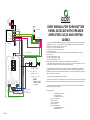
1
s.r.l.
12Vac
230Vac
21809
21809ke
acet
around the world
22510B
CALL 7
AUDIO OUT
AUDIO IN
AC IN
GROUND 0 V
AC IN
6
5
4
3
2
1
1 2 3 4 5 6 7
Speaker Amplifier
21323
TO T.P. 6 OF HANDSET T1
T1
5
6
7
8
9
*
0
#
RL2 = RELAY 2, 1A
combination 1, 2 and 3
combination 7 = RL1 + RL2
acet
5KPx1001
27/09/2005
N.O. = normally open
SW = switch
N.C. = normally closed
Page SE1
RL1 = RELAY 1, 5A
combination 4, 5 and 6
RL2
4
SE2
N.O.2
SW2
N.C.2
3
DC + out (max 500mA)
AC in
Common in
DC in
Battery
2
1
2
3
4
5
RL1
N.O.1
SW1
N.C.1
10460x
1
USER MANUAL FOR PUSH BUTTON
PANEL ELS01DG WITH SPEAKER
AMPLIFIER 21323 AND KEYPAD
104602
Here are to be described installation and use of the digital keypads ACET mod. 104602.The keypad
is capable to store up to 1 + 7 codes; the first code is the MASTER, and it is used to enter the programmin mode, while the remaining 7 are user codes:
_3 codes ‘01’, ‘02’, ‘03’ for relay RL2 (Max 1A)
_3 codes ‘04’, ‘05’, ‘06’ for relay RL1 (Max 5A)
_1 code ‘07’ for both relay
it is possible to activate only the required number of codes; each code NEEDS to be 5 digit long.
Please note that :
_’01 code has been setted as 01234
_’04 code has been setted as 12345
_’07 code has been setted as 11111
always is possible to change or unvalidate the codes following the below instruction.
The keypad is usually delivered with only onr code inserted, i.e. the master code, stated at ‘ 00123 ‘
: The codes can be changed by the user with the following procedures.
The keypad includes a membrane 12-key keyboard, a green LED indicator lamp, a red LED indicator lamp and a buzzer; all these devices concurr during operation or programming operations; the
programming of the system is done from the keyboard, with no need to move switches or jumpers, so
with no need to open the enclosure.
The green LED shows that the sistem is in stand-by
Each keypress is confirmed by a short beep sound, while a missed code causes a long beep; the LED
lamp will indicate a correct code (the LED will remain on for all the time the output relay is activated).
The codes are stored in a maintenence free non-volatile memory with 10 years data retention; no
battery or backup supply is necessary.
Terminal description:
1
2
3
4
5
NO1 Normaly open for RL1
SW1 Switch for RL1
NC1 Normaly closed RL1
Out for DC low current
In for AC segnal
In for common segnal
In for DC segnal
In /Out from/to Battery
NO2 Normaly open for RL2
SW2 Switch for RL2
NC2 Normaly closed for RL2
-A) INSTALLATION HINTS and REQUIREMENTS
Furthermore, the value ‘00’ is reserved to the master code, and this code will never activate the
output.
==========================================
After the selection of the code the user has to introduce the old value: after the introduction of the
exact value a medium length beep is output: now it is possible to enter the new code, 5 digit long;
after the 5th digit a beep signals the code has been entered.
The maximum voltage appliable to the relay contact is 24 V; a service pushbutton BS, which will
activate the output for all the time it is hold pressed, can be connected to the connection header.
The connection diagram is shown on the last page; it shows how to connect the optional backup
battery and the clock PE that can be used to enable the service pushbutton only within specified time
slots: the battery is charged from the keypad when the mains power is present.
If the selected code was not already used a double beep and it is possible to intoduce immediately
the value.
It is possible to clear a code simply selecting the value ‘00000’ as the new code.
B) LEARNING MODE ENTERING
=============================
The first operation requested to allow programming operation is to enter the learning phase instead
of the working condition: to obtain this the user has to introduce the master code, stated in factory as
‘00123’; after this operation the red LED will blink to confirm the instruction phase has been entered.
Now it is possible change either the codes or the length of the ON time of the output (relay).
B.1) OUTPUT LENGTH SETTING
=============================
It is possible to choose between several active output times, depending on the kind of lock; the
selected time is choosen by pressing ONE key, from ‘1’ to ‘8’ and followed by ‘A’ to confirm the selection.
The times allowed are:
THE SYSTEM WILL NOT ACCEPT ‘00000’ AS THE MASTER CODE.
B.3) END OF PROGRAMMING
==========================
The end of the learning phase is obtained by pressing ‘0’ and ‘*’ keys: the keypad will go back to the
working condition, with all the codes updated.
NOTE
=========
In case of wrong selection it is possible to clear ALL the operation from the beginning of the last
sequence pressing the ‘#’ key: the system will come back to the condition of just entering the learning
phase (end of phase B).
Once entered the learning condition it is possible to perform several operations, such as programming many codes, without exiting the learning phase, but simply performing the required setting
operations described above in sequence (Sec. B.1 and B.2).
Key ‘1’ -> 1 second
Key ‘2’ -> 2 seconds
Key ‘3’ -> 4 seconds
Key ‘4’ -> 8 seconds
It is possible, if needed, to restore the master code to the default factory value; the procedure is the
following:
Key ‘5’ -> 10 seconds
a) Remove power supply (either mains and/or battery);
Key ‘6’ -> 15 seconds
b) Wait about 10 seconds to ensure proper power off;
Key ‘7’ -> 20 seconds
c) Hold down at both “ * “ , “0” and “ # “ keys;
Key ‘8’ -> 25 seconds
Key ‘9’ -> 28 seconds
d) Reconnect power while the previous keys are hold presed: the LED will blink at a speed
rate to confirm
The selected value is stored as soon as the ‘*’ key is pressed.
B.2) CODE SETTING
==================
The first operation requested is the selection of the code to be changed: this is obtained by pressing
TWO keys an confirming them with ‘*’ key; this number can range from ‘00’ to ‘07’ : please note that
it is required a TWO digit number before the confirm key ‘*’, so the user has to type, for example, ‘03’
if he wishes to change the value of the third user code.
Page MASTER CODE CLEARING
==========================
the proper execution of the operation;
e) Remove power, wait 10 seconds and reconnect it: the keypad will work with the default
master code.
Please be informed that this procedure will work ONLY when the system is powered on, and this
combination of ‘ * ‘, ‘0’ and ‘ # ‘ keys will be considered as an error during normal operation; all the
tenant’s codes are unaffected.