1
© 2012 Mercury Marine
*8M0071455*
90-8M0071455 512
TABLE OF CONTENTS
Section 1 - Overview - Identifying Your Systems
Identifying DTS and Non‑DTS SmartCraft Systems.................. 2
Non‑DTS.............................................................................. 2
DTS Controls........................................................................ 3
Yacht Control.................................................................. 3
Helm‑Mounted DTS Controls......................................... 3
SportFish DTS Remote Control...................................... 4
Joystick........................................................................... 5
Auxiliary Joystick Station................................................ 5
Section 2 - Getting to Know Your Power Package
Emergency Stop Switch............................................................. 8
Lanyard Stop Switch.................................................................. 8
Instrumentation.......................................................................... 9
VesselView........................................................................... 9
SmartCraft Speedometer and Tachometer Digital Gauges 10
System Link Digital Gauges............................................... 10
Electronic Helm Steering......................................................... 11
Throttle Only Operation............................................................ 11
Throttle Only....................................................................... 11
Neutral Safety Throttle Only............................................... 11
Section 3 - On The Water
Starting and Stopping the Engines.......................................... 14
Starting an Engine Using the VIP SmartStart Switch......... 14
Stopping the Engine Using the VIP SmartStart Switch...... 16
Panel Mount Features.............................................................. 17
Slim Binnacle Control Features and Operation........................ 18
Helm Transfer................................................................... 19
Synchronizing Helms Prior to Helm Transfer............... 20
Dual Handle Console Control with DTS Trackpad................... 20
Dual Handle Console Control with DTS Trackpad Features
and Operation................................................................... 20
Synchronizing Engines..................................................... 22
Helm Transfer................................................................... 22
Synchronizing Helms Prior to Transfer......................... 23
Dual Handle Yacht Console Control with DTS Trackpad......... 23
Dual Handle Yacht Console Control with DTS Trackpad
Features and Operation.................................................... 23
Synchronizing Engines..................................................... 25
Helm Transfer................................................................... 25
Synchronizing Helms Prior to Transfer......................... 26
SportFish Control..................................................................... 26
SportFish Remote Control Operation............................... 26
Maneuvering with the Joystick................................................. 26
Special Digital Throttle and Shift (DTS) Features.................... 31
Troll and Throttle Response............................................... 32
Dock................................................................................... 33
Throttle Only....................................................................... 33
Single Lever ("1 Lever") Operation..................................... 34
Sync................................................................................... 34
Precision Pilot.......................................................................... 35
Precision Pilot Trackpad Features.................................... 35
General Information...................................................... 35
Standby........................................................................ 35
Standby and Active Lights............................................ 36
Power Icon.................................................................... 37
Skyhook (if Equipped)....................................................... 37
Engaging (Activating) Skyhook..................................... 38
Disengaging (Deactivating) Skyhook............................ 40
Auto Heading.................................................................... 40
Engaging Auto Heading................................................ 40
Course Adjustment Using the Turn Buttons or
Joystick......................................................................... 41
To Resume a Heading ................................................. 42
Disengaging Auto Heading........................................... 42
Response Button.............................................................. 43
Track Waypoint................................................................. 44
Engaging Track Waypoint Mode.................................. 45
Disengaging Track Waypoint Mode.............................. 45
Turn Buttons or Joystick in Track Waypoint Mode....... 46
Auto Heading Button in Track Waypoint Mode ............ 46
Acknowledging a Turn During a Waypoint Arrival........ 46
Waypoint Sequence..................................................... 47
Axius Premier Precision Pilot Trackpad Functions.................. 49
Port Engine Only Operation..................................................... 51
Section 4 - Engine Room
Vessel Interface Panel (VIP) ................................................... 54
Starting and Stopping the Engines................................... 54
Starting an Engine Using the VIP SmartStart Switch... 54
Stopping the Engine Using the VIP SmartStart Switch 56
Electrical System Overload Protection............................. 57
Vessel Interface Panel (VIP) Overload Protection........ 57
90-8M0071455
eng
MAY 2012
Overload Protection for the DC Voltage Regulator
System, If Equipped .................................................... 58
Overload Protection for Other Circuits.......................... 58
Contingent Operations............................................................. 59
Steering—Emergency Alternative Method........................ 59
Port Engine Only Operation.............................................. 59
Page i
Gear Engagement—Emergency Procedure.................... 59
Steering and Trim—Manual Override.............................. 60
Procedure for a Stuck Steering Control Valve............ 62
Procedure for a Stuck Trim Tab Control Valve........... 62
Section 5 - Troubleshooting
Troubleshooting Engine Related Problems............................ 64
Electrical Connections............................................................ 64
Check VesselView First.......................................................... 64
SmartCraft Circuits Overload Protection................................ 64
Engine Will Not Start.............................................................. 64
VesselView Troubleshooting.................................................. 64
Poor Performance.................................................................. 65
Joystick................................................................................... 65
Electronic Remote Controls.................................................... 65
Steering System..................................................................... 66
Diagnosing DTS Problems..................................................... 66
Diagnosing the Junction Box.................................................. 67
Standard Junction Box ..................................................... 67
Smart Junction Box .......................................................... 67
Galvanic Isolator..................................................................... 68
Section 6 - Customer Assistance Information
Owner Service Assistance...................................................... 70
Local Repair Service......................................................... 70
Service Away From Home................................................ 70
Stolen Power Package..................................................... 70
Attention Required After Submersion............................... 70
Replacement Service Parts.............................................. 70
Parts and Accessories Inquiries....................................... 70
Page ii
Resolving a Problem......................................................... 70
Customer Service Literature................................................... 71
English Language............................................................. 71
Other Languages.............................................................. 71
Ordering Literature................................................................. 71
United States and Canada................................................ 71
Outside the United States and Canada............................ 71
90-8M0071455
eng
MAY 2012
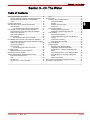
Section 1 - Overview - Identifying Your Systems
Section 1 - Overview - Identifying Your Systems
1
Table of Contents
Identifying DTS and Non‑DTS SmartCraft Systems............... 2
Non‑DTS ......................................................................... 2
DTS Controls .................................................................. 3
Yacht Control ........................................................... 3
90-8M0071455
eng
MAY 2012
Helm‑Mounted DTS Controls .................................. 3
SportFish DTS Remote Control ............................... 4
Joystick .................................................................... 5
Auxiliary Joystick Station ......................................... 5
Page 1
Section 1 - Overview - Identifying Your Systems
Identifying DTS and Non‑DTS SmartCraft Systems
There are a variety of SmartCraft control systems available for your Mercury Diesel power package. Digital gauges can be used
on a power package that uses a cable actuated remote control, and is considered a non‑DTS application. A power package
helm system that is controlled and managed through a control area network (CAN) can be easily identified. This manual will
help identify the types of controls and give a brief overview of the SmartCraft CAN digital throttle and shift (DTS) controls and
operation.
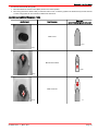
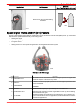
Non‑DTS
A vessel equipped with this type of control system, in many cases, incorporates mechanical lever controls which use cables to
control the engine throttle and gear position. These types of controls generally require more effort to move the control levers
from the idle neutral position into gear and into a higher engine RPM. The following graphic shows an example of mechanical
lever controls.
34968
Single and dual mechanical lever controls
The boatbuilder may have installed an electronic throttle and shift (ETS) system. An ETS system is offered through a number of
different manufacturers. These ETS types of controls are SmartCraft systems compatible, but cannot integrate with the
SmartCraft CAN system. These types of controls use a dedicated communication harness that is not incorporated into the
SmartCraft CAN communication network.
34954
ETS control
Page 2
90-8M0071455
eng
MAY 2012
Section 1 - Overview - Identifying Your Systems
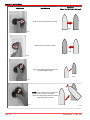
DTS Controls
Yacht Control
A vessel equipped with a SmartCraft electronic remote control (ERC), typically has a DTS trackpad integrated on the base of
the control. The DTS trackpad is used to enable or disable features of the DTS system; auto synchronization, throttle only, etc.
Any ERC that includes a DTS trackpad, or a DTS trackpad installed at the helm, is a DTS control system.
34959
DTS yacht control
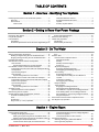
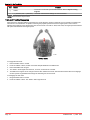
Helm-Mounted DTS Controls
There are many different types of ERC's in the DTS system that control single or dual engine applications. Controls may, or
may not, have integrated "START/STOP" buttons in the base of the control and may, or may not, have trim switches in the
control handle. Controls with trim switches incorporated into the handle are for sterndrive installations. Controls without trim
switches in the handle are generally for inboard applications.
35167
Slim binnacle ERC
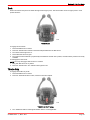
35168
Dual engine console mount ERC with trim switches and DTS trackpad
90-8M0071455
eng
MAY 2012
Page 3
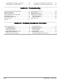
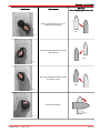
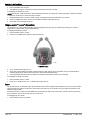
Section 1 - Overview - Identifying Your Systems
35169
Dual engine console mount ERC with DTS trackpad
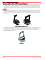
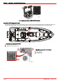
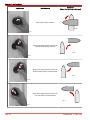
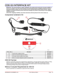
SportFish DTS Remote Control
The SportFish remote control is a unique design for use on center console sportfishing vessels. The controls are mounted on
the port and starboard side of the console. The SportFish remote control can be used with a dash‑mounted trackpad.
a
b
41318
Overhead view of mounting locations
a - Port side console mount
b - Starboard side console mount
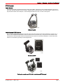
a
b
a
b
SportFish remote control and trackpad
a - DTS trackpad
b - ERC handle
c - Transfer button
c
44090
Page 4
90-8M0071455
eng
MAY 2012
Section 1 - Overview - Identifying Your Systems
Joystick
There are advanced versions of the DTS system available on certain dual engine vessels; Axius utilizes sterndrives for
propulsion, and Zeus utilizes an innovative pod drive propulsion that is mounted perpendicular to the bottom of the hull. These
types of propulsion systems use the SmartCraft ERC and a joystick. The joystick is used primarily for docking maneuvers. An
optional helm‑mounted Precision Pilot or Axius trackpad can be incorporated for autopilot features; "AUTO HEADING,"
"WAYPOINT SEQUENCE," or "SKYHOOK," all based on a GPS signal that is interfaced with the CAN system.
50629
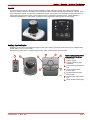
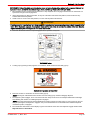
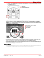
Auxiliary Joystick Station
Depending on the version of the SmartCraft engine control system used to operate the vessel, there may be multiple auxiliary
joystick stations (up to four per vessel).
Each auxiliary joystick station is equipped with an E‑stop switch, auxiliary joystick, and a trackpad.
a
b
e
d
c
f
CENTER
PORT
ALARM
h
STBD
TRANSFER
g
43428
90-8M0071455
eng
MAY 2012
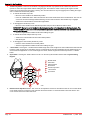
Typical auxiliary joystick station
components for triple drives
a - E‑stop switch
b - Auxiliary joystick
c - Joystick trackpad for triple
installations
d - Port drivetrain status indicator
light
e - Center drivetrain status
indicator light
f - Starboard drivetrain status
indicator light
g - Transfer button and indicator
light
h - Alarm and fault indicator light
Page 5
Section 1 - Overview - Identifying Your Systems
a
b
d
c
PORT
ALARM
i
e
f
g
STBD
TRANSFER
h
43429
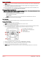
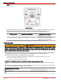
Page 6
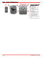
Typical auxiliary joystick station
components for quad drives
a - E‑stop switch
b - Auxiliary joystick
c - Joystick trackpad for quad
installations
d - Port outer drivetrain status
indicator light
e - Port center drivetrain status
indicator light
f - Starboard center drivetrain
status indicator light
g - Starboard outer drivetrain
status indicator light
h - Transfer button and indicator
light
i - Alarm and fault indicator light
90-8M0071455
eng
MAY 2012
Section 2 - Getting to Know Your Power Package
Section 2 - Getting to Know Your Power Package
Table of Contents
Emergency Stop Switch......................................................... 8
Lanyard Stop Switch............................................................... 8
Instrumentation....................................................................... 9
VesselView ..................................................................... 9
SmartCraft Speedometer and Tachometer Digital
Gauges ......................................................................... 10
90-8M0071455
eng
MAY 2012
System Link Digital Gauges .........................................
Electronic Helm Steering......................................................
Throttle Only Operation........................................................
Throttle Only .................................................................
Neutral Safety Throttle Only .........................................
10
11
11
11
11
2
Page 7
Section 2 - Getting to Know Your Power Package
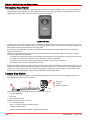
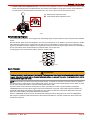
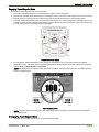
Emergency Stop Switch
An emergency stop (E‑stop) switch is used to turn off the engines in an emergency situation, such as a person overboard or a
tangled propeller. When activated, an E‑stop switch interrupts the power supply to the engine and transmission. If the boat is
equipped with an E‑stop switch, the E‑stop switch turns off all of the engines.
35308
Typical E-stop switch
Activation of an E‑stop switch stops the engine, or engines, immediately, but the boat can continue to coast for some distance
depending upon the velocity and degree of any turn at shutdown. While the boat is coasting, it can cause injury to anyone in the
boat's path as seriously as the boat would when under power.
We recommend instructing other occupants on proper starting and operating procedures should they need to operate the
engine in an emergency.
Accidental or unintended activation of the switch during normal operation is also possible, which can cause any or all of the
following potentially hazardous situations:
•
Occupants can be thrown forward due to unexpected loss of forward motion, and passengers in the front of the boat could
be ejected over the bow and possibly struck by the propulsion or steering components.
•
The operator can lose power and directional control in heavy seas, strong current, or high winds.
•
The operator can lose control of the vessel when docking.
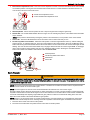
Restarting an engine using the key switch or start button after an E‑stop shutdown without first turning the key switch to the off
position for at least 30 seconds will restart the engine but cause fault codes to be set. Unless you are in a potentially hazardous
situation, turn the key switch off and wait at least 30 seconds before restarting the engine or engines. If after restarting, some
fault codes are still being displayed, contact your authorized Mercury Diesel repair facility.
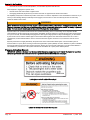
Lanyard Stop Switch
The purpose of a lanyard stop switch is to turn off the engine when the operator moves outside the operator's position (as in
accidental ejection from the operator's position).
c
b
a
RUN
OFF
a - Stop switch
b - Lanyard
c - Clips to the operator
74608
Accidental ejections, such as falling overboard, are more likely to occur in:
•
low‑sided sport boats
•
bass boats
•
high performance boats
Accidental ejections can also occur from:
•
poor operating practices
•
sitting on the seat or gunwale at planing speeds
•
standing at planing speeds
•
operating at planing speeds in shallow or obstacle infested waters
Page 8
90-8M0071455
eng
MAY 2012
Section 2 - Getting to Know Your Power Package
•
releasing your grip on the steering wheel that is pulling in one direction
•
consuming alcohol or drugs
•
high speed boating maneuvers
The lanyard is a cord usually between 122 and 152 cm (4 and 5 ft) in length when stretched out, with an element on one end
made to be inserted into the switch and a snap on the other end for attaching to the operator. The lanyard is coiled to make its
at‑rest condition as short as possible to minimize the likelihood of lanyard entanglement with nearby objects. Its stretched‑out
length is made to minimize the likelihood of accidental activation should the operator choose to move around in an area close
to the normal operator's position. If it is desired to have a shorter lanyard, wrap the lanyard around the operator's wrist or leg, or
tie a knot in the lanyard.
Activation of the lanyard stop switch will stop the engine immediately, but the boat will continue to coast for some distance
depending upon the velocity and degree of any turn at shut down. However, the boat will not complete a full circle. While the
boat is coasting, it can cause injury to anyone in the boat's path as seriously as the boat would when under power.
We strongly recommend that other occupants be instructed on proper starting and operating procedures should they be
required to operate the engine in an emergency (e.g. if the operator is accidentally ejected).
! WARNING
If the operator falls out of the boat, stop the engine immediately to reduce the possibility of serious injury or death from being
struck by the boat. Always properly connect the operator to the stop switch using a lanyard.
Accidental or unintended activation of the switch during normal operation is also a possibility. This could cause any, or all, of
the following potentially hazardous situations:
•
Occupants could be thrown forward due to unexpected loss of forward motion, a particular concern for passengers in the
front of the boat who could be ejected over the bow and possibly struck by the propulsion or steering components.
•
Loss of power and directional control in heavy seas, strong current or high winds.
•
Loss of control when docking.
! WARNING
Avoid serious injury or death from deceleration forces resulting from accidental or unintended stop switch activation. The boat
operator should never leave the operator's station without first disconnecting the stop switch lanyard from the operator.
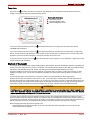
Instrumentation
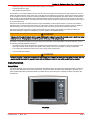
VesselView
Your power package may be connected to a SmartCraft VesselView display. The interactive VesselView display continuously
reports real‑time information about speed, performance, engine fault codes, fuel status, water temperature and depth, and
other operating data. When VesselView detects a problem with any connected system, it displays an alarm message to the
boat operator.
27198
VesselView
90-8M0071455
eng
MAY 2012
Page 9
Section 2 - Getting to Know Your Power Package
VesselView may also be connected to other vessel systems such as GPS, generators, and cabin environmental controls. This
vessel integration allows the operator to monitor and control a wide range of vessel systems from a single display.
Refer to your VesselView operations manual for detailed instructions on how to operate this display.
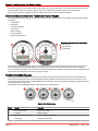
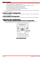
SmartCraft Speedometer and Tachometer Digital Gauges
The SmartCraft instrument package, if equipped, augments the information provided by VesselView. The instrument package
may display:
•
Engine RPM
•
Boat speed
•
Coolant temperature
•
Oil pressure
•
Battery voltage
•
Fuel consumption
•
Engine operating hours
b
a
c
SmartCraft tachometer and speedometer
a - Tachometer
b - Speedometer
c - LCD display
50400
The SmartCraft instrument package also aids in identifying the fault codes associated with the engine audio warning system.
The SmartCraft instrument package displays critical engine alarm data and other potential problems on its LCD display.
For basic operation information on the SmartCraft instrument package and for details on the warning functions monitored by the
system, refer to the manual provided with your gauge package.
System Link Digital Gauges
Some instrumentation packages include gauges that augment the information provided by VesselView and the SmartCraft
tachometer and speedometer. The owner and operator should be familiar with all the instruments and their functions on the
boat. Because of the large variety of instrumentation and manufacturers, have your boat dealer explain the gauges and normal
readings that appear on your boat.
The following types of digital gauges may be included with your power package.
a
b
c
d
37925
System Link digital gauges
Item
Gauge
Indicates
a
Oil pressure gauge
Engine oil pressure
b
Voltmeter
Battery voltage
c
Water temperature gauge
Engine operating temperature
d
Fuel gauge
Quantity of fuel in tank
Page 10
90-8M0071455
eng
MAY 2012
Section 2 - Getting to Know Your Power Package
Electronic Helm Steering
The electronic helm steering operates using electrical signals. A computer‑controlled electric motor attached to the steering
wheel simulates the resistance feedback found in hydraulic steering systems.
We recommend that you drive carefully (in an open area clear of obstructions or other boat traffic) until you are familiar with the
system's handling characteristics and the boat's response. The electronic steering may provide a faster steering response than
expected.
To confirm your steering range from lock to lock, ensure that the starboard engine key switch is on. The engines do not have to
be running. Turn the wheel to starboard until the wheel stops at the starboard lock or end‑stop. The end‑stop is electronically
set by the electric motor attached to the steering wheel. Begin turning the wheel to port and count the number of revolutions
until the wheel stops at the port lock. The number of wheel revolutions you counted moves the drives from the maximum
starboard angle to maximum port angle, with the center (straight‑ahead position) being 0°. The maximum steering angles are
controlled within the vessel personality developed by the drive manufacturer and the boat OEM.
In certain situations the electronic end‑stops of the wheel are not felt. The absence of noticeable end‑stops does not affect the
steering. The drives will still stop when they reach the full turn position at each lock. The absence of end‑stops can be the result
of the starboard key switch in the off position, a low starboard battery voltage, or a steering wheel motor fault.
Your vessel's personality, as developed by the vessel manufacturer in partnership with the drive manufacturer, determines the
number of turns lock to lock. Typically, this is approximately 2‑3/4 revolutions of the wheel. The OEM may request different lock
to lock settings for other boat models.
Throttle Only Operation
There are two methods of engaging the throttle only operation mode. Throttle only allows the operator to control the engine
throttle without shifting into gear. This feature is useful to warm‑up the engine. The first method can be engaged when the
engine is running. The second method can only be engaged prior to starting the engine and is considered a neutral safety
feature.
Throttle Only
1.
To activate the throttle only mode:
a.
Move the control handle to the idle/neutral position.
b.
Press the "THROTTLE ONLY" button and advance the control handle ahead to the forward detent. The horn will
sound once and the neutral light will start flashing. The horn will sound twice when throttle only is engaged.
NEUTRAL
-
NEUTRAL
-
SYNC
1 LEVER
THROTTLE
ONLY
35203
Slim binnacle
2.
TRANSFER
DOCK
1 LEVER
c.
+
SFER
TRAN
SYNC
START
STOP
TROLL
+
TROLL
THROTTLE
ONLY
DOCK
35204
Yacht control
Advance the control handle to increase the engine RPM.
To disengage the throttle only mode:
a.
Move the control handle into the idle/neutral position and press the "THROTTLE ONLY" button.
IMPORTANT: Moving the control handle into the idle/neutral position will not deactivate the throttle only mode. The
"THROTTLE ONLY" button on the DTS trackpad must be pressed to deactivate the throttle only mode and allow the
engine to shift into gear.
b.
Allow the engine RPM to stabilize at idle before shifting into gear.
Neutral Safety Throttle Only
The engines will start if the control levers are not in neutral. This forces the control of the engine RPM to idle only and the RPM
cannot be increased. If the engine stalls or is turned off by the "START/STOP" button, the key switch must be turned "OFF" and
"ON" before the engine will start again with the control lever not in the neutral position.
1.
To activate the neutral safety throttle only mode:
90-8M0071455
eng
MAY 2012
Page 11
Section 2 - Getting to Know Your Power Package
2.
a.
Advance the control handle into the forward detent position.
b.
Start the engine.
To disengage the neutral safety throttle only mode:
a.
Place the control handle into the neutral position.
b.
Allow the engine RPM to stabilize at idle before shifting into gear.
Page 12
90-8M0071455
eng
MAY 2012
Section 3 - On The Water
Section 3 - On The Water
Table of Contents
Starting and Stopping the Engines....................................... 14
Starting an Engine Using the VIP SmartStart Switch ... 14
Stopping the Engine Using the VIP SmartStart
Switch ........................................................................... 16
Panel Mount Features.......................................................... 17
Slim Binnacle Control Features and Operation.................... 18
Helm Transfer................................................................ 19
Synchronizing Helms Prior to Helm Transfer ........ 20
Dual Handle Console Control with DTS Trackpad............... 20
Dual Handle Console Control with DTS Trackpad
Features and Operation................................................. 20
Synchronizing Engines.................................................. 22
Helm Transfer................................................................ 22
Synchronizing Helms Prior to Transfer .................. 23
Dual Handle Yacht Console Control with DTS Trackpad..... 23
Dual Handle Yacht Console Control with DTS Trackpad
Features and Operation................................................. 23
Synchronizing Engines.................................................. 25
Helm Transfer................................................................ 25
Synchronizing Helms Prior to Transfer .................. 26
SportFish Control.................................................................. 26
SportFish Remote Control Operation............................ 26
Maneuvering with the Joystick.............................................. 26
Special Digital Throttle and Shift (DTS) Features................. 31
Troll and Throttle Response ......................................... 32
Dock ............................................................................. 33
Throttle Only ................................................................. 33
Single Lever ("1 Lever") Operation ............................... 34
90-8M0071455
eng
MAY 2012
Sync .............................................................................. 34
Precision Pilot....................................................................... 35
Precision Pilot Trackpad Features................................. 35
General Information ............................................... 35
Standby ................................................................. 35
Standby and Active Lights ..................................... 36
Power Icon ............................................................ 37
Skyhook (if Equipped).................................................... 37
Engaging (Activating) Skyhook ............................. 38
Disengaging (Deactivating) Skyhook .................... 40
Auto Heading................................................................. 40
Engaging Auto Heading ........................................ 40
Course Adjustment Using the Turn Buttons or
Joystick .................................................................. 41
To Resume a Heading ......................................... 42
Disengaging Auto Heading .................................... 42
Response Button........................................................... 43
Track Waypoint.............................................................. 44
Engaging Track Waypoint Mode ........................... 45
Disengaging Track Waypoint Mode ...................... 45
Turn Buttons or Joystick in Track Waypoint
Mode ..................................................................... 46
Auto Heading Button in Track Waypoint Mode .... 46
Acknowledging a Turn During a Waypoint
Arrival .................................................................... 46
Waypoint Sequence .............................................. 47
Axius Premier Precision Pilot Trackpad Functions............... 49
Port Engine Only Operation.................................................. 51
3
Page 13
Section 3 - On The Water
Starting and Stopping the Engines
Your Zeus power package is equipped with a SmartStart system, that includes a start/stop button for emergency use that is
remotely mounted in the vessel interface panel (VIP). The VIP is usually located in the engine room.
In normal circumstances, start and stop the engine from the helm using the start/stop button of the SmartStart system.
NOTICE
The seawater pumps on vessels equipped with Zeus pod drives can be damaged by excessive exhaust aeration due to
inadequate water flow. To ensure adequate water flow across the seawater inlets, make sure that the vessel is underway
before exceeding 1500 RPM.
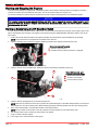
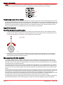
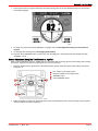
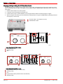
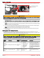
Starting an Engine Using the VIP SmartStart Switch
You may desire to start an engine from the engine room or under certain circumstances the engine control systems may not be
able to automatically start an engine. The engines can be started using the "SMARTSTART" (start/stop) switch on the VIP for
each engine.
1.
Perform the checks and steps listed in the engine's operation and maintenance manual available for this package.
2.
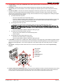
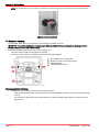
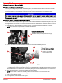
Open the seawater return seacock, if equipped. Rotate the handle in the direction indicated by the arrow.
NOTE: Some vessels are not equipped with a seawater return seacock.
Drive cover removed for clarity
a - Handle in open position
b - Seawater return (overboard) seacock, if equipped
a
b
41198
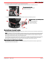
3.
Open the seacock for the seawater inlet. Rotate the handle in the direction indicated by the arrow.
b
Typical inlet seacock—port
orientation (starboard similar)
a - Seacock for seawater inlet
b - Handle in open position
c - Former position (closed)
a
c
41197
4.
5.
6.
7.
8.
Open the seacock (if equipped) for any accessory equipment.
NOTE: When the key switch is turned to the on position the neutral LED lights, on the ERC trackpad, flash on and off if the
ERC handles are not in the neutral position. Before starting the engines the ERC handles must be in the neutral position.
At the active standard helm, move the ERC handles to the neutral position.
NOTE: Ask your dealer for the location of the key switches if the key switches are not located at the helm.
Turn the key switch to the on position for each engine to be started.
Verify it is safe to start the engines.
In the engine room, locate the VIP for each engine.
Page 14
90-8M0071455
eng
MAY 2012
Section 3 - On The Water
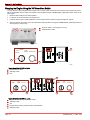
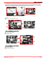
IMPORTANT: The start/stop switch or "SMARTSTART" switch on a VIP will start the corresponding engine regardless of
which helm station is active or previously active.
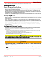
9.
Inside the VIP for triple or quad installations, turn the engine selector switch to the desired engine or engines.
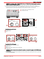
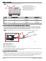
10. Press and release the start/stop switch or green "SMARTSTART" (start/stop) switch on the VIP corresponding to the
engine being started. The control system automatically controls the starter to achieve a successful start.
b
a
a - "E‑STOP" switch—for emergency use only
b - "START/STOP" switch
50531
CENTER
ENGINE
PORT
ENGINE
c
STBD
ENGINE START/STOP
a
b
43957
Typical SmartCraft 3.0 VIP for triples
a - Engine selector switch
b - Start/stop switch
c - VIP
c
PORT
CENTER
ENGINE
PORT
ENGINE
START/STOP
a
b
STBD
CENTER
ENGINE
d
STBD
ENGINE
START/STOP
e
44350
Typical SmartCraft 3.0 VIP for quads
a - Engine selector switch (port and port center)
b - Start/stop switch
c - VIP
d - Engine selector switch (starboard center and starboard)
e - Start/stop switch
IMPORTANT: To avoid excessive exhaust aeration of the seawater, do not operate the engines over 1500 RPM when the
vessel is at rest.
11. If you must operate the engines above 1500 RPM, put the vessel underway with a light throttle load until the engines reach
normal operating temperature.
90-8M0071455
eng
MAY 2012
Page 15
Section 3 - On The Water
Stopping the Engine Using the VIP SmartStart Switch
You may desire to stop an engine from the engine room or under certain circumstances the engine control system may not be
able to automatically stop an engine. The engines can be stopped using the "SMARTSTART" ((start/stop) switch on the VIP for
each engine.
1.
Move the ERC handles to the neutral position.
2.
Locate the VIP for each engine in the engine room.
3.
Inside the VIP for triple or quad installations, turn the engine selector switch to the desired engine or engines.
4.
When the engines are running, press and release the start/stop switch or the green "SMARTSTART" ((start/stop) switch for
each engine you want to stop.
b
a
a - "E‑STOP" switch—for emergency use only
b - "START/STOP" switch
50531
CENTER
ENGINE
PORT
ENGINE
c
STBD
ENGINE START/STOP
a
b
43957
Typical SmartCraft 3.0 VIP for triples
a - Engine selector switch
b - Start/stop switch
c - VIP
c
PORT
ENGINE
a
PORT
CENTER
ENGINE
START/STOP
b
STBD
CENTER
ENGINE
d
STBD
ENGINE
START/STOP
e
44350
Typical SmartCraft 3.0 VIP for quads
a - Engine selector switch (port and port center)
b - Start/stop switch
c - VIP
d - Engine selector switch (starboard center and starboard)
e - Start/stop switch
Page 16
90-8M0071455
eng
MAY 2012
Section 3 - On The Water
5.
Turn the key switch to the off position for each engine that was stopped.
6.
Close the seawater return seacock, if equipped. Rotate the handle in the direction indicated by the arrow.
Drive cover removed for clarity
a - Seawater return seacock, if equipped
b - Handle in closed position
a
b
41199
7.
Close the seacock for the seawater inlet. Rotate the handle in the direction indicated by the arrow.
b
Typical inlet seacock—port orientation (starboard
similar)
a - Seacock for seawater inlet
b - Former position (open)
c - Handle in closed position
a
c
41196
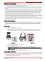
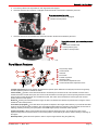
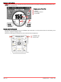
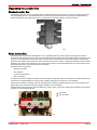
Panel Mount Features
d
c
e
b
-
+
f
h
a
g
3409
abcdefgh-
Lanyard stop switch
Control handle
Shift lock
Trim switch
Throttle only button
Start/stop button
Detent tension adjustment screw
Control handle friction adjustment screw
Lanyard stop switch ‑ Turns the ignition off whenever the operator (when attached to the lanyard) moves far enough away
from the operator's position to activate the switch.
Control handle ‑ Operation of the shift and throttle are controlled by the movement of the control handle. Push the control
handle forward from neutral with a quick, firm motion to the first detent for forward gear. Continue pushing forward to increase
speed. Pull the control handle back from neutral with a quick, firm motion to the first detent for reverse gear and continue
pushing back to increase speed.
Shift lock ‑ Pressing the shift lock allows the engine to shift. The shift lock must always be pressed when moving the control
handle out of the neutral position.
Trim switch (if equipped) ‑ Power trim allows the operator to adjust the drive angle while underway, to provide the ideal boat
angle for varying load and water conditions. Also, the trailering feature allows the operator to raise and lower the drive unit for
trailering, beaching, launching, low speed (below 1200 RPM engine speed), and shallow water operation.
Throttle only button ‑ Allows engine throttle advancement without shifting the engine. The throttle only button can be
depressed only when the remote control is in the neutral position, and should only be used to assist in starting or warming up
the engine.
Start/stop button ‑ Allows the boat operator to start or stop the engine without using the ignition key.
90-8M0071455
eng
MAY 2012
Page 17
Section 3 - On The Water
Detent tension adjustment screw ‑ This screw can be adjusted to increase or decrease the effort required to move the control
handle out of the detent positions. Turning the screw clockwise will increase tension and counterclockwise to decrease tension.
The cover must be removed to access this screw.
Control handle friction adjustment screw ‑ This screw can be adjusted to increase or decrease the friction on the control
handle. This will help prevent unwanted motion of the handle in rough water. Turn the screw clockwise to increase friction and
counterclockwise to decrease friction. The cover must be removed to access this screw.
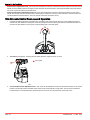
Slim Binnacle Control Features and Operation
1.
Operation of shift and throttle is controlled by the movement of the control handle. Push the control handle forward from
neutral to the first detent for forward gear. Continue pushing forward to increase speed. Pull the control handle back from
neutral to the first detent for reverse gear. Continue pulling back to increase speed.
N
F
R
12871
2.
Trim switch (if equipped) ‑ Pressing the trim switch allows the engine to trim up or down.
a - Trim switch
a
12874
3.
Control handle friction adjustment screw ‑ This screw can be adjusted to increase or decrease the friction on the control
handle. This will help prevent unwanted motion of the remote control handle in rough water. Turn the screw clockwise to
increase friction or counterclockwise to decrease friction. The cover must be removed to access this screw.
Page 18
90-8M0071455
eng
MAY 2012
Section 3 - On The Water
4.
Detent tension adjustment screw ‑ This screw can be adjusted to increase or decrease the effort to move control handle
out of detent positions. Turning the screw clockwise will increase tension or counterclockwise to decrease tension. The
cover must be removed to access this screw.
a - Detent tension adjustment screw
b - Control handle friction adjustment screw
a
b
28556
5.
Start/stop button ‑ Allows the boat operator to start or stop the engine without using the ignition key.
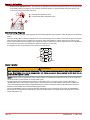
6.
Neutral LED ‑ The neutral LED illuminates when the engine is in the neutral gear position. It also flashes when the throttle
only is activated.
7.
Active LED ‑ The active LED illuminates to show the remote control is active and ready for use.
8.
Throttle only/station select button ‑ Allows the boat operator to increase engine RPM for warm‑up, without shifting the
engine into gear. To engage throttle only, move the control handle into the neutral position. Press the "THROTTLE ONLY"
button while moving the control handle ahead to the forward detent. The horn will sound once and the neutral light will start
flashing. The horn will sound twice when throttle only is engaged. Advance throttle to increase engine RPM. To disengage,
return control handle to neutral position and press the "THROTTLE ONLY" button. Pressing the "STATION SELECT"
button at an inactive helm initiates a helm transfer. Refer to Helm Transfer.
NOTE: Gear position is determined by sensing the position of the shift actuator, not the position of the control handle.
c
abcd-
a
Start/stop button
Throttle only/station select button
Neutral LED
Active LED
START
STOP
d
b
22970
Helm Transfer
! WARNING
Avoid serious injury or death from loss of boat control. The boat operator should never leave the active station while engine is
in gear. Helm transfer should only be attempted while both stations are manned. One‑person helm transfer should only be
performed while engine is in neutral.
NOTE: Idle position is preferred when doing a helm transfer. If conditions do not allow the remote control to be placed at idle
position, a helm transfer can be done while in gear.
NOTE: The active light on the remote control will be illuminated at the helm that is in control of the engine.
The helm transfer function allows the boat operator to select which helm is in control of engine operation. Pressing the throttle
only/station select button two times allows engine control to be transferred to a new helm. When a helm transfer is initiated, the
control will automatically start adjusting engine RPM and gear position to match the control handle setting at the new helm.
Adjust the control handles to the desired throttle and gear position.
NOTE: There is a 10 second time frame to complete a helm transfer. If the helm transfer is not completed, the action will be
cancelled and a double beep will sound. Pressing the throttle only/station select button again will reinitiate a helm transfer.
1. Place the active remote control lever to idle position.
2. Proceed to the inactive helm and position remote control lever to the idle position.
90-8M0071455
eng
MAY 2012
Page 19
Section 3 - On The Water
3.
Press throttle only/station select button two times. The "ACTIVE" light will illuminate to indicate the remote control is in
control of the engine.
a
START
STOP
b
a - Active light
b - Throttle only/station select button
22608
4.
The "ACTIVE" light will switch off at the original helm.
Synchronizing Helms Prior to Helm Transfer
Pressing the throttle only/station select button one time allows the boat operator 10 seconds to match up the control handle
setting at the new station with the handle setting that is at the old (to be inactive) station. If the handle is not matched, the
neutral light will flash. The light blinks faster as the handle is nearing match position. Once the light stays on continuously, the
handle is matched and the throttle only/station select button can be pressed again to complete the transfer. This completes the
transfer process, and gives control to the new station. If the helm transfer is not completed within 10 seconds, the helm transfer
is cancelled.
Dual Handle Console Control with DTS Trackpad
Dual Handle Console Control with DTS Trackpad Features and Operation
1.
Operation of shift and throttle is controlled by the movement of the control handle. Push the control handle forward from
neutral to the first detent for forward gear. Continue pushing forward to increase speed. Pull the control handle back from
neutral to the first detent for reverse gear. Continue pulling back to increase speed.
N
R
F
3417
2.
Trim switch (if equipped) ‑ Pressing the trim switch allows the sterndrive to trim up and down.
L
RA
UT
NE
+
L
OL
TR
ER
SF
AN
-
TR
CK
DO
NC
SY
LE
TT
RO
TH ONLY
R
VE
1 LE
22132
3.
4.
Neutral lights ‑ The neutral lights illuminate when the engine is in the neutral gear position. The lights will flash when the
engine is in the throttle only mode.
NOTE: Gear position is determined by the position of the shift actuator, not the position of the control handle.
Troll button ‑ "TROLL" has two specific functions and the functionality is dependent on the type of drive that is installed on
the vessel.
•
When the drive is equipped with the troll function, the mode allows the vessel to be operated at very low speeds by
controlling the transmission. The transmission is capable of reducing the propeller speed lower than the engine
speed. The levers are adjusted so that trolling occurs within the first 25% of lever travel. From 26% to 100% lever
travel, the engine is commanded between idle speed and maximum rated engine speed. This feature should not be
used for docking maneuvers. To turn the troll control off, press the "TROLL" button, move the throttle to a different
speed, or shift the engine into neutral.
•
When the drive is not equipped with the troll function, the reduced idle speed RPM will work with all CMD engines,
with exception to the QSD product. This feature can be used to reduce a vessel's speed for a slow, no wake situation.
This feature should not be used for docking maneuvers. To turn the troll control off, press the "TROLL" button, move
the throttle to a different speed, or shift the engine into neutral.
Page 20
90-8M0071455
eng
MAY 2012
Section 3 - On The Water
5.
Transfer button ‑ Pressing the "TRANSFER" button allows engine operation to be transferred from a different helm. Refer
to Helm Transfer.
6.
Dock button ‑ Pressing the "DOCK" button initiates docking mode. Docking mode reduces throttle capacity to
approximately 50% of normal throttle. To turn off the docking mode, shift the engine into neutral and press the "DOCK"
button.
7.
Throttle only button ‑ There are two methods of engaging the throttle only operation mode. Throttle only allows the
operator to control the engine throttle without shifting into gear. This feature is useful to warm‑up the engine. The first
method can be engaged when the engine is running. The second method can only be engaged prior to starting the engine
and is considered a neutral safety feature.
a.
To activate the throttle only mode:
• Move the control handle to the idle/neutral position.
• Press the "THROTTLE ONLY" button and advance the control handle ahead to the forward detent. The horn will
sound once and the neutral light will start flashing. The horn will sound twice when throttle only is engaged.
• Advance the control handle to increase the engine RPM.
b.
To disengage the throttle only mode:
• Move the control handle into the idle/neutral position and press the "THROTTLE ONLY" button.
IMPORTANT: Moving the control handle into the idle/neutral position will not deactivate the throttle only mode. The
"THROTTLE ONLY" button on the DTS trackpad must be pressed to deactivate the throttle only mode and allow the
engine to shift into gear.
• Allow the engine RPM to stabilize at idle before shifting into gear.
a.
To activate the neutral safety throttle only mode:
• Advance the control handle into the forward detent position.
• Start the engine.
b.
To disengage the neutral safety throttle only mode:
• Place the control handle into the neutral position.
• Allow the engine RPM to stabilize at idle before shifting into gear.
8.
1 lever button ‑ Pressing the "1 LEVER" button initiates single lever mode. Single lever mode enables the throttle and shift
functions of both engines to be controlled by the port control handle for sterndrive applications, and the starboard lever for
Zeus and inboard applications. To turn off the single lever mode, shift the engine into neutral and press the "1 LEVER"
button.
9.
Sync button ‑ Pressing the "SYNC" button turns off or on the auto synchronization feature. Refer to Synchronizing
Engines.
abcdefg-
a
L
RA
UT
NE
b
NEUTRAL
-
TROLL
+
SYNC
Neutral LEDS
Troll button
Transfer button
Dock button
Throttle only button
1 lever button
Sync button
c
TRANSFER
g
1 LEVER
THROTTLE
ONLY
DOCK
d
f
e
22133
10. Control handle friction adjustment screw ‑ This screw can be adjusted to increase or decrease the friction on the control
handle. This will help prevent unwanted motion of the remote control handle in rough water. Turn the screw clockwise to
increase friction or counterclockwise to decrease friction. The cover must be removed to access this screw.
90-8M0071455
eng
MAY 2012
Page 21
Section 3 - On The Water
11. Detent tension adjustment screw ‑ This screw can be adjusted to increase or decrease the effort to move control handle
out of detent positions. Turning the screw clockwise will increase tension or counterclockwise to decrease tension. The
cover must be removed to access this screw.
a - Detent tension adjustment screw
b - Control handle friction adjustment screw
a
b
28556
Synchronizing Engines
The auto synchronizing feature, when engaged, will automatically adjust all engine speeds to match the speed of the starboard
engine.
Press the "SYNC" button on the DTS trackpad to turn auto synchronization on or off. When the sync LED is yellow, the "SYNC"
button has been pressed, but the conditions are not right for auto synchronization to engage. When the sync LED turns red,
engine synchronization has been engaged. The engines will remain synchronized as long as engine speed is over 900 RPM for
two seconds and the remote control handles are positioned within 10% of each other.
To disengage the auto synchronization feature, press the "SYNC" button.
NEUTRAL
-
TROLL
+
SYNC
1 LEVER
TRANSFER
THROTTLE
ONLY
DOCK
22590
Helm Transfer
! WARNING
Avoid serious injury or death from loss of boat control. The boat operator should never leave the active station while engine is
in gear. Helm transfer should only be attempted while both stations are manned. One‑person helm transfer should only be
performed while engine is in neutral.
NOTE: Neutral position is preferred when doing a station transfer. If conditions do not allow the remote control to be placed in
the neutral position, a helm transfer can be done while in gear.
The helm transfer function allows the boat operator to select which helm is in control of engine operation. Pressing the
"TRANSFER" button two times allows engine control to be transferred to a new helm. When a helm transfer is initiated, the
control will automatically start adjusting engine RPM and gear position to match the control handle setting at the new helm.
Adjust the control handles to the desired throttle and gear position.
Once the "TRANSFER" button is pressed, the transfer LED will light up and one beep will sound. Press the "TRANSFER"
button again to complete the helm transformation. When helm transformation is complete, another beep will sound and the
transfer LED will turn off.
Page 22
90-8M0071455
eng
MAY 2012
Section 3 - On The Water
NOTE: There is a 10 second time frame to complete a helm transfer. If the helm transfer is not completed, the action will be
cancelled and a double beep will sound. Pressing the "TRANSFER" button again will reinitiate a helm transfer.
NEUTRAL
TROLL
-
+
SYNC
TRANSFER
1 LEVER
THROTTLE
ONLY
DOCK
22593
Synchronizing Helms Prior to Transfer
Pressing the "TRANSFER" button allows the boat operator 10 seconds to match up the control handle settings at the new helm
with the handle settings that are at the old (to be inactive) helm. If the handles are not matched, the neutral lights will flash. The
light blinks faster as the handles are nearing match position. Once the light stays on continuously, the handles are matched and
the button can be pressed again to complete the transfer. This completes the transfer process, and gives control to the new
station. If the helm transfer is not completed within 10 seconds, the action will be cancelled.
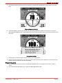
Dual Handle Yacht Console Control with DTS Trackpad
Dual Handle Yacht Console Control with DTS Trackpad Features and Operation
1.
Operation of shift and throttle is controlled by the movement of the control handle. Push the control handle forward from
neutral to the first detent for forward gear. Continue pushing forward to increase speed. Pull the control handle back from
neutral to the first detent for reverse gear. Continue pulling back to increase speed.
N
F
78
O
R
78
O
24559
2.
3.
4.
5.
Neutral lights ‑ The neutral lights illuminate when the engine is in the neutral gear position. The lights will flash when the
engine is in the throttle only mode.
NOTE: Gear position is determined by the position of the shift actuator, not the position of the control handle.
Troll button ‑ "TROLL" has two specific functions and the functionality is dependent on the type of drive that is installed on
the vessel.
•
When the drive is equipped with the troll function, the mode allows the vessel to be operated at very low speeds by
controlling the transmission. The transmission is capable of reducing the propeller speed lower than the engine
speed. The levers are adjusted so that trolling occurs within the first 25% of lever travel. From 26% to 100% lever
travel, the engine is commanded between idle speed and maximum rated engine speed. This feature should not be
used for docking maneuvers. To turn the troll control off, press the "TROLL" button, move the throttle to a different
speed, or shift the engine into neutral.
•
When the drive is not equipped with the troll function, the reduced idle speed RPM will work with all CMD engines
with exception to the QSD product. This feature can be used to reduce a vessel's speed for a slow, no wake situation.
This feature should not be used for docking maneuvers. To turn the troll control off, press the "TROLL" button, move
the throttle to a different speed, or shift the engine into neutral.
Transfer button ‑ Pressing the "TRANSFER" button allows engine operation to be transferred from a different helm. Refer
to Helm Transfer.
Dock button ‑ Pressing the "DOCK" button initiates docking mode. Docking mode reduces throttle capacity to
approximately 50% of normal throttle. To turn off the docking mode, shift the engine into neutral and press the "DOCK"
button.
90-8M0071455
eng
MAY 2012
Page 23
Section 3 - On The Water
6.
Throttle only button ‑ There are two methods of engaging the throttle only operation mode. Throttle only allows the
operator to control the engine throttle without shifting into gear. This feature is useful to warm‑up the engine. The first
method can be engaged when the engine is running. The second method can only be engaged prior to starting the engine
and is considered a neutral safety feature.
a.
To activate the throttle only mode:
• Move the control handle to the idle/neutral position.
• Press the "THROTTLE ONLY" button and advance the control handle ahead to the forward detent. The horn will
sound once and the neutral light will start flashing. The horn will sound twice when throttle only is engaged.
• Advance the control handle to increase the engine RPM.
b.
To disengage the throttle only mode:
• Move the control handle into the idle/neutral position and press the "THROTTLE ONLY" button.
IMPORTANT: Moving the control handle into the idle/neutral position will not deactivate the throttle only mode. The
"THROTTLE ONLY" button on the DTS trackpad must be pressed to deactivate the throttle only mode and allow the
engine to shift into gear.
• Allow the engine RPM to stabilize at idle before shifting into gear.
a.
To activate the neutral safety throttle only mode:
• Advance the control handle into the forward detent position.
• Start the engine.
b.
To disengage the neutral safety throttle only mode:
• Place the control handle into the neutral position.
• Allow the engine RPM to stabilize at idle before shifting into gear.
7.
1 lever button ‑ Pressing the "1 LEVER" button initiates single lever mode. Single lever mode enables the throttle and shift
functions of both engines to be controlled by the port control handle for sterndrive applications and the starboard lever for
Zeus and inboard applications. To turn off the single lever mode, shift the engine into neutral and press the "1 LEVER"
button.
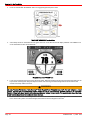
8.
Sync button ‑ Pressing the "SYNC" button turns off or on the auto synchronization feature. Refer to Synchronizing
Engines.
abcdefg-
a
NEUTRAL
-
b
NEUTRAL
+
TROLL
SFER
TRAN
SYNC
1 LEVER
THROTTLE
ONLY
DOCK
-
TROLL
Neutral LEDS
Troll button
Transfer button
Dock button
Throttle only button
1 lever button
Sync button
+
SYNC
c
TRANSFER
g
1 LEVER
THROTTLE
ONLY
d
f
e
9.
DOCK
24561
Detent tension adjustment screw ‑ This screw can be adjusted to increase or decrease the effort to move control handle
out of detent positions. Turning the screw clockwise will increase tension or counterclockwise to decrease tension. The
cover must be removed to access this screw.
Page 24
90-8M0071455
eng
MAY 2012
Section 3 - On The Water
10. Control handle friction adjustment screw ‑ This screw can be adjusted to increase or decrease the friction on the control
handle. This will help prevent unwanted motion of the remote control handle in rough water. Turn the screw clockwise to
increase friction or counterclockwise to decrease friction. The cover must be removed to access this screw.
a - Detent tension adjustment screw
b - Control handle friction adjustment screw
a
b
24543
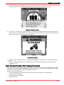
Synchronizing Engines
The auto synchronizing feature, when engaged, will automatically adjust all engine speeds to match the speed of the starboard
engine.
Press the "SYNC" button on the DTS trackpad to turn auto synchronization on or off. When the sync LED is yellow, the "SYNC"
button has been pressed, but the conditions are not right for auto synchronization to engage. When the sync LED turns red,
engine synchronization has been engaged. The engines will remain synchronized as long as engine speed is over 900 RPM for
two seconds and the remote control handles are positioned within 10% of each other.
To disengage the auto synchronization feature, press the "SYNC" button.
NEUTRAL
-
TROLL
+
SYNC
1 LEVER
TRANSFER
THROTTLE
ONLY
DOCK
22590
Helm Transfer
! WARNING
Avoid serious injury or death from loss of boat control. The boat operator should never leave the active station while engine is
in gear. Helm transfer should only be attempted while both stations are manned. One‑person helm transfer should only be
performed while engine is in neutral.
NOTE: Neutral position is preferred when doing a station transfer. If conditions do not allow the remote control to be placed in
the neutral position, a helm transfer can be initiated while in gear. The remote control handle (throttle) must be within 5% of the
remote control handle idle position to complete a helm transfer while in gear.
The helm transfer function allows the boat operator to select which helm is in control of engine operation. Pressing the
"TRANSFER" button two times allows engine control to be transferred to a new helm. When a helm transfer is initiated, the
control will automatically start adjusting engine RPM and gear position to match the control handle setting at the new helm.
Adjust the control handles to the desired throttle and gear position.
Once the "TRANSFER" button is pressed, the transfer LED will light up and one beep will sound. Press the "TRANSFER"
button again to complete the helm transformation. When helm transformation is complete, another beep will sound and the
transfer LED will turn off.
90-8M0071455
eng
MAY 2012
Page 25
Section 3 - On The Water
NOTE: There is a 10 second time frame to complete a helm transfer. If the helm transfer is not completed, the action will be
cancelled and a double beep will sound. Pressing the "TRANSFER" button again will reinitiate a helm transfer.
NEUTRAL
-
TROLL
+
SYNC
1 LEVER
TRANSFER
THROTTLE
ONLY
DOCK
22593
Synchronizing Helms Prior to Transfer
Pressing the "TRANSFER" button allows the boat operator 10 seconds to match up the control handle settings at the new helm
with the handle settings that are at the old (to be inactive) helm. If the handles are not matched, the neutral lights will flash. The
light blinks faster as the handles are nearing match position. Once the light stays on continuously, the handles are matched and
the button can be pressed again to complete the transfer. This completes the transfer process, and gives control to the new
station. If the helm transfer is not completed within 10 seconds, the action will be cancelled.
SportFish Control
SportFish Remote Control Operation
1.
Operation of shift and throttle is controlled by the movement of the control handle. Push the control handle forward from
neutral to the first detent for forward gear. Continue pushing forward to increase speed. Pull the control handle back from
neutral to the first detent for reverse gear. Continue pulling back to increase speed.
a
a - Neutral
41356
2.
The SportFish remote control requires the installation of the helm‑mounted CAN pad for throttle only, synchronization,
station transfer, troll control, single lever mode, and docking mode operations when applicable. Refer to the operations
manual included with the helm‑mounted CAN pad.
Maneuvering with the Joystick
The joystick provides single lever interface to maneuver the vessel. Operating the vessel with the joystick is well suited for
close quarter operations and when docking. The joystick causes the control system to independently control each pod angle
and thrust to move or rotate the boat in a desired direction. For example, if you move the joystick sideways, the control system
commands the boat in the sideways direction.
The joystick gives three axis control: fore and aft, port and starboard, and rotational, or any combination thereof. For example,
moving the joystick to port causes the boat to move sideways to port. Rotating the joystick causes the boat to rotate around its
center. You can move and rotate the joystick at the same time, allowing for very intricate movements for maneuvering in tight
quarters.
The control system automatically attempts to dampen bow and stern swinging (referred to as yaw) during joystick operation. An
on‑board sensor measures the yaw rate of the boat and actively counteracts the yaw motion of the boat. Factors, such as wind,
water conditions or vessel loading, may act upon the vessel beyond the systems capability to correct yaw. Manual yaw
correction may be required when commanding the boat in the fore and aft, port and starboard, or diagonal directions. To correct
for unintended yaw during any maneuver just rotate the joystick in the direction the bow is desired to rotate.
The following table gives some limited examples of the basic responses to inputs from the joystick. The joystick is proportional,
which means that the farther from the center the joystick is moved, the more thrust is applied to the boat in that direction.
Page 26
90-8M0071455
eng
MAY 2012
Section 3 - On The Water
To maneuver the boat with the joystick:
1.
Move both electronic remote control (ERC) levers to the neutral position.
2.
Move the joystick in the direction that you want the boat to move, or twist the joystick in the direction that you want the boat
to rotate. The joystick can be moved and rotated at the same time.
Joystick Input and Boat Response Table
Joystick Input
Boat Response
Movement
(shown from light gray to dark gray)
Boat at rest
25911
24704
Boat moves forward
25928
24705
Boat moves aft
24706
90-8M0071455
eng
MAY 2012
25927
Page 27
Section 3 - On The Water
Joystick Input
Boat Response
Movement
(shown from light gray to dark gray)
Boat moves to starboard without rotating
25929
24707
Boat moves to port without rotating
25931
24708
Boat moves diagonally forward and to the
starboard without rotating
25926
24709
NOTE: In this maneuver move and twist the
joystick for yaw correction, if required.
Boat moves diagonally forward and rotates
starboard for yaw correction
24715
Page 28
37774
90-8M0071455
eng
MAY 2012
Section 3 - On The Water
Joystick Input
Boat Response
Movement
(shown from light gray to dark gray)
Boat moves diagonally aft and to the
starboard without rotating
25924
24710
Boat moves diagonally aft and to the port
without rotating
25923
24711
Boat moves diagonally forward and to the
port without rotating
25925
24712
Boat rotates clockwise
25921
24713
90-8M0071455
eng
MAY 2012
Page 29
Section 3 - On The Water
Joystick Input
Boat Response
Movement
(shown from light gray to dark gray)
Boat rotates counter clockwise
25920
24714
Boat moves diagonally forward and to the
starboard while rotating clockwise
25916
24715
Boat moves diagonally forward and to the
starboard while rotating counterclockwise
25918
24718
Boat moves diagonally forward and to the
port while rotating counterclockwise
25917
24719
Page 30
90-8M0071455
eng
MAY 2012
Section 3 - On The Water
Joystick Input
Movement
(shown from light gray to dark gray)
Boat Response
Boat moves to the port while rotating
clockwise
25930
24720
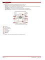
Special Digital Throttle and Shift (DTS) Features
The DTS system features several alternate operational modes for the electronic remote control (ERC) levers. Any of the listed
features can be operated simultaneously and can help you with:
•
Warming the engines
•
Synchronizing the engines
•
Trolling the vessel
•
Allowing access to the slow speed trolling features of the integrated transmission system
a
h
b
c
g
f
d
e
28090
ERC levers with DTS trackpad
Item
Control
Function
a
"NEUTRAL" lights
Illuminate when the transmission is in the neutral gear position. The lights flash
when the engine is in the throttle only mode.
b
"TROLL"
"TROLL" reduces the propeller speed lower than the engine speed for the first
25% of lever travel.
c
"TRANSFER"
Allows boat control to be transferred to a different helm. Refer to Helm
Transfer.
d
"DOCK"
Reduces throttle capacity to approximately 50% of normal throttle.
e
"THROTTLE ONLY"
Allows the boat operator to increase engine RPM for warm‑up, without shifting
the transmission into gear.
f
"1 LEVER"
Enables the throttle and shift functions of both engines to be controlled by the
port control handle for sterndrive applications, and the starboard lever for Zeus
and inboard applications.
90-8M0071455
eng
MAY 2012
Page 31
Section 3 - On The Water
Item
Control
Function
g
"SYNC"
Turns off or on the auto synchronization feature. Refer to Synchronizing
Engines.
h
"+" (increase) and "–" (decrease)
Increases and decreases settings for various functions.
NOTE: Not all functions may be active.
Troll and Throttle Response
When the drive is equipped with the troll function, the mode allows the vessel to operate at very low speeds by controlling the
transmission. The transmission is capable of reducing the propeller speed lower than the engine speed. Lever control is
adjusted so that trolling occurs within the first 25% of lever travel. From 26% to 100% lever travel, the engine operates between
idle speed and maximum rated engine speed.
31463
"TROLL" button
To engage the troll mode:
1.
Place both ERC levers in neutral.
2.
Press the "TROLL" button, located on the DTS trackpad attached to the ERC levers.
3.
Place either ERC lever into gear.
4.
The "TROLL" button lights when the lever, or levers, are moved out of neutral.
5.
The RPM of the engines do not change for the first 25% of ERC lever travel, while the transmissions allow some slippage
at lower speeds. Engine RPM rises through the remaining 75% of lever travel.
To disengage the troll mode:
1.
Bring both ERC levers to neutral.
2.
Press the "TROLL" button. The "TROLL" button light turns off.
Page 32
90-8M0071455
eng
MAY 2012
Section 3 - On The Water
Dock
Dock mode reduces the percent of throttle throughout the range by 50%. This allows better control of engine power in close
quarter situations.
31464
"DOCK" button
To engage the dock mode:
1. Place both ERC levers in neutral.
2. Press the "DOCK" button located on the DTS trackpad attached to the ERC levers.
3. The "DOCK" button light turns on.
4. Place either ERC lever into gear.
5. The engines raise the RPM at a proportionally lower RPM for the ERC lever position, and with half the power that is usually
available.
To disengage the dock mode:
NOTE: Dock only disengages with the levers in a detent.
1. Bring both ERC levers to any detent.
2. Press the "DOCK" button. The "DOCK" button light turns off.
Throttle Only
To engage the throttle only mode:
1. Place both ERC levers in neutral.
2. Press the "THROTTLE ONLY" button, located on the DTS trackpad.
31465
"THROTTLE ONLY" button
3.
The "THROTTLE ONLY" button light illuminates and the neutral lights blink.
90-8M0071455
eng
MAY 2012
Page 33
Section 3 - On The Water
4.
Place either ERC lever into gear.
5.
The RPM of the engines can be raised, while the transmission remains in neutral.
To disengage the throttle only mode:
NOTE: Pressing the "THROTTLE ONLY" button while the ERC levers are in gear turns off the button light, but the boat remains
in throttle only mode until you place the levers in neutral.
1. Bring both ERC levers to neutral. Throttle only will not disengage unless the ERC levers are in neutral.
2. Press the "THROTTLE ONLY" button. The "THROTTLE ONLY" button light turns off.
3. Notice that the neutral lights remain on.
Single Lever ("1 Lever") Operation
The single lever ("1 Lever") feature simplifies engine management during rough sea conditions by allowing you to grasp a
single lever to command both engines simultaneously.
To engage the single lever mode:
1.
Place both ERC levers in neutral.
2.
Press the "1 LEVER" button located on the DTS trackpad.
31466
"1 LEVER" button
3.
The "1 LEVER" button light turns on.
4.
Single lever mode enables the throttle and shift functions of both engines to be controlled by the port control handle for
sterndrive applications, and the starboard lever for Zeus and inboard applications.
5.
The engine RPM raises and lowers simultaneously while the transmissions remain in the same gear.
To disengage the single lever mode:
1.
Place both ERC levers in neutral.
2.
Press the "1 LEVER" button. The "1 LEVER" button light turns off.
Sync
The system features an automatic engine synchronization feature which engages automatically at key‑up. The synchronization
feature monitors the position of both levers. If both levers are within 10% of one another, the port engine synchronizes to the
starboard engine's RPM.
VesselView shows an orange icon if the RPM of the engines are not within 10% of each other, and the icon turns green when
they synchronize. The icon turns grey when sync mode is off.
To disengage the sync mode:
1.
Place the ERC levers in any detent.
Page 34
90-8M0071455
eng
MAY 2012
Section 3 - On The Water
2.
Press the "SYNC" button.
31467
"SYNC" button
To engage the sync mode, press the "SYNC" button.
Precision Pilot
Precision Pilot Trackpad Features
General Information
Precision Pilot trackpad features includes:
•
Precision Pilot (or Pilot) functions are controlled through the Pilot trackpad only.
•
Pilot screens are located under the Environment chapter of VesselView.
•
The "TURN" buttons provide a 10° course correction for each press to the port or starboard.
•
The "AUTO HEADING", "TRACK WAYPOINT", and "WAYPOINT SEQUENCE" buttons engage automatic course and
heading modes.
•
The steering wheel feels locked into a detent when Auto Heading or Track Waypoint are engaged. Manually overcoming
the detent force of the steering wheel automatically puts Pilot into Standby mode.
Standby
The elements of the Standby screen are:
•
In standby mode, the display shows a digital compass value and the angle of the drives.
•
The compass value is the actual current heading from Pilot.
•
On the right side of the screen, an icon labeled "OFF" indicates that Pilot is not engaged.
90-8M0071455
eng
MAY 2012
Page 35
Section 3 - On The Water
NOTE: Not all of the functions of Precision Pilot work when DTS functions are engaged. Disengage the DTS functions to use
the functions of Precision Pilot.
a
Standby screen on VesselView
a - "OFF" icon
b - Heading
c - Drive angle reference
d - Engine RPM
b
d
c
31408
Standby and Active Lights
Precision Pilot is disengaged (off) when the "STANDBY" light is illuminated. You must press the button for Auto Heading, Track
Waypoint, or Skyhook to engage a mode.
When the "ACTIVE" light is illuminated one mode of Precision Pilot is engaged (on).
a
b
a - "STANDBY" light
b - "ACTIVE" light
27695
Page 36
90-8M0071455
eng
MAY 2012
Section 3 - On The Water
Power Icon
The power icon
located on the buttons for Skyhook, Auto Heading, and Track Waypoint indicate that the buttons can
engage or disengage the Precision Pilot function they perform.
Buttons with Power icons
a - "SKYHOOK" button
b - "AUTO HEADING" button
c - TRACK WAYPOINT" button
a
c
b
27696
If you press a button that has the power icon
"STANDBY" light illuminates.
when that button light is on, the light turns off for that button and the
when that button light is off, the light turns on for that button, a single beep
If you press a button that has the power icon
sounds, and the "ACTIVE" light illuminates, unless another mode is currently active. If another mode is currently active, press
the button on the active mode to disengage it, then press the button for the new mode.
If you press a button with the power icon
and the "ACTIVE" light illuminates.
when that button light is off, the light turns on for that button, a single beep sounds,
Skyhook (if Equipped)
Your vessel may be equipped with a station keeping feature called Skyhook. Skyhook automatically maintains the heading and
position of the boat within about 3 m (10 ft) of a set position. The control system for Skyhook uses GPS and compass heading
information to automatically control shift, throttle, and steering to keep the boat in approximately one position.
The Skyhook feature can hold your boat nearly stationary, for example, while you wait for a space at the fuel dock, or while
waiting for a bridge to open. You can also use Skyhook to maintain your boat's position when the water is too deep for an
anchor.
To unlock and be able to use this feature you will have to contact your authorized Mercury Diesel repair facility.
Skyhook should not be used when the boat is next to a dock, or any other object, including other anchored boats. Because
Skyhook holds the boat in an approximate position, not a precise one, it can cause your boat to collide with objects close to the
boat causing damage to the boat and the nearby objects. Occasionally the Skyhook system may apply a brief surge in power
while holding a position. This may cause a person standing near the edge of the boat to lose their balance and fall.
! WARNING
A rotating propeller, a moving boat, or a device attached to a moving boat can cause serious injury or death to people in the
water. When Skyhook is engaged, the propellers rotate and the boat moves to maintain the position of the boat. Stop the
engines immediately whenever anyone is in the water near the boat.
To engage Skyhook the drives must be shifted into neutral. However, after engaging Skyhook the drive response is not the
same as with drives normally shifted into neutral. The propellers will turn when Skyhook is activated, and propeller rotation may
not be obvious. As in all boats when the engines are running, it is important to ensure no one is in the water near the boat and
that the passengers are secure. Compliance with this practice is even more important when Skyhook is engaged.
Before engaging (activating) Skyhook the operator must:
•
Inform passengers how Skyhook operates, to stay out of the water and off the swim platform, and to be alert for any
sudden shifts in the boat position.
90-8M0071455
eng
MAY 2012
Page 37
Section 3 - On The Water
•
Check to see no one is on the swim platform, or in the water anywhere near the boat.
When Skyhook is engaged the operator must:
•
Remain at the helm and maintain a vigilant watch.
•
Disengage (deactivate) Skyhook if anyone enters the water or approaches the boat from the water.
The capability of Skyhook to maintain the position of the boat in a current is dependent on the characteristics of the boat. If you
notice your boat drifting sideways while Skyhook is engaged, move the bow or stern more directly into the current to help
reduce the effects of the current.
! WARNING
When the Skyhook is engaged, the boat stays in a preset position; however, Skyhook can disengage unexpectedly. When
Skyhook disengages, the boat does not hold the preset position and may drift, causing the potential of damage or personal
injury. The helm operator must be able to take control of the boat when using Skyhook.
Skyhook relies on an operational GPS receiver and operational heading sensor. Occasionally, due to imperfect satellite
communications, the GPS signal may be temporarily unavailable. Skyhook continues to operate through a GPS signal outage
for up to 10 seconds, but automatically disengages if the GPS signal outage persists. If Skyhook disengages, you are alerted
by the sound of a horn and the indicator light on the Precision Pilot keypad for the "SKYHOOK" button turns off. In such a
circumstance, the boat will drift with the wind or current because the engines continue to run, but the drive units are now in
neutral.
Skyhook performance is largely dictated by the performance of the onboard Zeus GPS system. The Zeus GPS system is
accurate within 3 m (10 ft) when receiving a wide area augmentation system (WAAS) correction. WAAS is a system of satellites
and ground stations that provide GPS signal corrections, allowing for more accurate positioning of your GPS. When WAAS is
not available, the performance of the system maintains the boat within 20 m (60 ft) of the desired position.
Engaging (Activating) Skyhook
IMPORTANT: Activities in the water near the vessel while Skyhook is engaged may result in injury. The Captain (or operator)
and passengers should read and observe the warning labels on the boat before Skyhook is engaged.
8M0034159
33798
Label adjacent to the Precision Pilot trackpad
33824
Label in the vicinity of the transom boarding area
Page 38
90-8M0071455
eng
MAY 2012
Section 3 - On The Water
IMPORTANT: If either of the labels cannot be located or are not legible, they must be replaced before engaging Skyhook. For
replacement labels, contact the manufacturer of your boat, or a Mercury Diesel authorized repair facility.
1.
Move the ERC levers to neutral and bring the boat to a stop. Skyhook will not engage until the boat is in neutral and at a
speed slow enough for safe engagement.
2.
Inform passengers how Skyhook operates, to stay out of the water and off the swim platform, and to be alert for any
sudden shifts in the boat position.
3.
Check to see no one is on the swim platform, or in the water anywhere near the boat.
! WARNING
A rotating propeller, a moving boat, or a device attached to a moving boat can cause serious injury or death to people in the
water. When Skyhook is engaged, the propellers rotate and the boat moves to maintain the position of the boat. Stop the
engines immediately whenever anyone is in the water near the boat.
4.
Press the "SKYHOOK" button to request engagement and operation of Skyhook.
27698
“SKYHOOK” button
5.
A safety pop‑up (warning screen) appears on VesselView. Read and observe the safety pop‑up.
33920
Skyhook warning screen on VesselView
6.
Press the X‑button on VesselView to close the safety pop‑up.
7.
The Skyhook system engages, and a one second solid horn beep sounds once. The trackpad "SKYHOOK" button light
stops blinking and remains on indicating Skyhook is engaged.
NOTE: Pressing the "SKYHOOK" button will also close the safety pop‑up and then disengage Skyhook.
8.
NOTE: Some boat manufacturers include additional (secondary) systems of sounds, lights, or other sources to alert you
and your passengers that Skyhook is engaged. See your boat manufacturer for information about additional Skyhook
notification systems, if equipped.
The VesselView "SKYHOOK" screen displays a green circle with the word "ON" when Skyhook engages. Refer to The
Skyhook Screen in VesselView.
90-8M0071455
eng
MAY 2012
Page 39
Section 3 - On The Water
NOTE: The boat may reverse automatically if it passed the position it was asked to hold—where the "SKYHOOK" button
was first pressed.
9. When Skyhook is engaged you must remain at the helm and maintain a vigilant watch. Disengage Skyhook if anyone
enters the water or approaches the boat from the water.
10. Press the "SKYHOOK" button a second time to put Precision Pilot in standby. All lights other than "STANDBY" turn off.
11. To disengage Skyhook, refer to Disengaging (Deactivating) Skyhook.
Disengaging (Deactivating) Skyhook
IMPORTANT: Both engines and drives must be operational for Skyhook to function. If the necessary reference signals from an
engine or drive become unavailable, Skyhook automatically disengages.
1.
To disengage the Skyhook, do one of the following:
•
Press the "SKYHOOK" button on the Precision Pilot trackpad.
•
Move any ERC lever out of neutral.
•
Move the joystick.
NOTE: In each method, the light on the Precision Pilot trackpad for the "SKYHOOK" button will turn off.
2.
A single horn beep sounds when the feature disengages.
Auto Heading
Auto Heading allows the boat to automatically maintain a compass heading while the boat is underway.
Engaging Auto Heading
1.
2.
3.
Place at least one running engine in forward gear.
NOTE: Auto Heading does not function with the ERC levers in neutral or reverse.
Steer the boat to the desired compass heading.
Press the "AUTO HEADING" button to engage the Auto Heading mode. The button illuminates and a single horn beep
sounds acknowledging engagement. A double horn beep sounds if Auto Heading does not engage.
a
b
abcd-
Port "TURN" (course adjust) button
Starboard "TURN" (course adjust) button
"RESUME" button
"AUTO HEADING" button
c
d
43579
4.
Display the "AUTOPILOT" screen on VesselView. Refer to Mode Display in VesselView.
5.
On the VesselView screen for autopilot, the mode indicator changes from "OFF" to "AUTO."
6.
The steering wheel will self‑center and be held in an electronic detent position.
NOTE: IIf you must turn the steering wheel for any reason, you will need to apply sufficient force to overcome the
electronic detent.
Page 40
90-8M0071455
eng
MAY 2012
Section 3 - On The Water
7.
Precision Pilot holds the compass heading the boat was following when the "AUTO HEADING" button was pressed and
Auto Heading engaged.
31409
8.
To adjust your course while "AUTO HEADING" is engaged, refer to Course Adjustment Using the Turn Buttons or
Joystick.
9.
To disengage Auto Heading refer to Disengaging Auto Heading.
10. Press the "AUTO HEADING" button a second time, Auto Heading goes to the standby mode and all lights other than
"STANDBY" turn off.
Course Adjustment Using the Turn Buttons or Joystick
While in "AUTO HEADING" mode, the "TURN" buttons (course adjust buttons) change the set course heading each time they
are pressed. Tapping the joystick left or right adjusts your course for each tap.
1.
Press the "TURN" button in the direction of the desired heading change. Each press of the button changes the desired
heading by 10°.
a
b
abcd-
Port "TURN" (course adjust) button
Starboard "TURN" (course adjust) button
"RESUME" button
"AUTO HEADING" button
c
d
43579
2.
Deflect and hold the joystick in the desired direction to make small adjustments in the chosen heading. Each recognized
movement adjusts the chosen heading by 1°.
90-8M0071455
eng
MAY 2012
Page 41
Section 3 - On The Water
NOTE: The joystick must move over 50% of its travel and a beep will sound for the movement to be recognized as input.
24707
Adjusting heading to starboard
To Resume a Heading
The "RESUME" button light is on if the previous course heading is available to resume.
IMPORTANT: The previous heading can only be resumed within one minute of the auto heading being disengaged or if the
steering wheel has been turned no more than 90°.
Press the "RESUME" button to resume the previous heading if you:
•
Turned the steering wheel and disengaged auto heading.
•
Pressed one of the "TURN" (course adjust) buttons with auto heading engaged.
a
b
abcd-
Port "TURN" (course adjust) button
Starboard "TURN" (course adjust) button
"RESUME" button
"AUTO HEADING" button
c
d
43579
Disengaging Auto Heading
1.
Disengage the auto heading mode with any of the following actions:
•
Place the ERC handles for both engines in neutral. The "AUTO HEADING" button light turns off and the standby light
comes on.
•
Turn the steering wheel beyond the electronic detent. The "AUTO HEADING" button light turns off and the resume
light comes on.
Page 42
90-8M0071455
eng
MAY 2012
Section 3 - On The Water
•
Press the "AUTO HEADING" button on the Precision Pilot trackpad. The "AUTO HEADING" button light turns off and
the standby light comes on.
a - Button light
b - "AUTO HEADING" button
a
b
43576
2.
A single horn beep sounds and the mode indicator changes from "AUTO" to "OFF."
3.
If Auto Heading disengaged because the steering wheel was turned, the resume button light turns on. While the resume
button light is on, you can press the "RESUME" button to resume the course in Auto Heading. Refer to To Resume a
Heading. If you do not wish to resume the course, press the "AUTO HEADING" button once to engage Standby and press
it again to turn the Auto Heading mode off.
a
abcd-
Mode indicator—"OFF" or "AUTO"
Current heading
Drive positions
Engine RPM
b
c
d
31408
4.
If the ERC handles were moved to neutral, the "AUTO HEADING" button light turns off and the "STANDBY" light comes
on. You cannot resume your course by pressing the "RESUME" button. Refer to To Resume a Heading.
5.
If Auto Heading disengaged because the "AUTO HEADING" button was pressed, the "AUTO HEADING" button light turns
off and the "STANDBY" light comes on. Press the "AUTO HEADING" button a second time and the "STANDBY" light goes
off, Auto Heading is disengaged, and the mode is "OFF."
Response Button
1.
Press the "RESPONSE" button to increase or decrease how aggressively the vessel reacts to programmed changes when
in the Pilot modes. How aggressively the vessel reacts equals a response setting in VesselView.
90-8M0071455
eng
MAY 2012
Page 43
Section 3 - On The Water
NOTE: Each time you press the "RESPONSE" button, the button light blinks to indicate you changed the response setting
for that mode.
27704
Response button
2.
3.
Press the "RESPONSE" button again to increase how aggressively the vessel reacts to programmed changes. The initial
button press shows the current response setting. Pressing the button as many as three times will increase how
aggressively the vessel reacts by three and then decrease it by returning to the first response setting.
Number of blinks
Response setting indicated
Aggressiveness of correction
1
1
Mild (for gentle or calm conditions)
2
2
Medium (for moderate conditions)
3
3
Aggressive (for severe conditions)
The value setting for the current amount of response appears on the Auto Heading page in VesselView.
Track Waypoint
! WARNING
In some Precision Pilot modes—"Auto Heading," "Track Waypoint," and "Waypoint Sequence"—the boat navigates a preset
course. The boat does not automatically respond to hazards such as other watercraft, obstacles, swimmers, or underwater
terrain. Collision with these hazards could cause boat damage, serious injury, or death. The operator must stay at the helm,
ready to evade hazards and warn others of course changes.
Track Waypoint allows the boat to automatically navigate to a specific waypoint or sequence of waypoints, called a waypoint
route. This feature is intended for use in open waters, free from obstructions above and below the waterline.
When the Track Waypoint feature is activated and the boat is in operation:
•
The helm must never be unattended. The feature is not designed to allow unattended operation of the vessel.
•
The operator must remain at the helm at all times.
•
It must not be used as the sole source of navigation.
IMPORTANT: Track Waypoint can only be used with chart plotters approved by Mercury Diesel.
Waypoint data needs to be provided to VesselView by a third party chart plotter. Refer to your chart plotter's user manual for
details.
The accuracy of the feature can be affected by environmental conditions and incorrect use. Observe the following information
when using the Track Waypoint and Waypoint Sequencing feature.
Waypoint data—distance settings
Between waypoints
Greater than 1.0 nautical mile (1.15 mile)
Arrival alarms
No less than 0.1 nautical mile (0.12 mile)
Page 44
90-8M0071455
eng
MAY 2012
Section 3 - On The Water
Engaging Track Waypoint Mode
To engage the Track Waypoint mode of Precision Pilot:
1.
Turn on the chart plotter and select a single waypoint or waypoint route to be tracked.
2.
Place at least one ERC handle in forward gear. Track Waypoint does not function if both handles are in neutral or reverse.
3.
Manually steer the boat to the direction of the first waypoint and hold the boat steady at a safe operating speed.
4.
Press the "TRACK WAYPOINT" button on the Precision Pilot keypad. The "TRACK WAYPOINT" button light turns on and
a single horn beep sounds, indicating Track Waypoint engaged. Pilot tracks to the first waypoint on the chart plotter course.
Two horn beeps sound if Track Waypoint does not engage.
27701
"TRACK WAYPOINT" button
5.
The VesselView "TRACK WAYPOINT" screen displays on VesselView for one second after pressing the "TRACK
WAYPOINT" button. The display shows the digital heading that the boat is traveling, the angles of the drives, and engine
speed in RPM. See Mode Display in VesselView.
NOTE: This display screen is activated during VesselView calibration. The GPS system generates the displayed heading
based on magnetic North.
31413
Track Waypoint screen
NOTE: Precision Pilot will not initiate turns when Track Waypoint mode is engaged. Turn features are only available in
Auto Heading mode.
Disengaging Track Waypoint Mode
1.
Disengage the Track Waypoint mode by one of the following methods:
90-8M0071455
eng
MAY 2012
Page 45
Section 3 - On The Water
2.
•
Press the "TRACK WAYPOINT" button on the Precision Pilot keypad. The "TRACK WAYPOINT" button light goes off
and Pilot goes to Standby. The "STANDBY" light turns on.
•
Turn the steering wheel hard enough to overcome the force feedback and Pilot goes to Standby.
•
Move both ERC levers back to neutral and Pilot goes to Standby.
•
Press either "TURN" button and Pilot goes to Auto Heading mode.
•
Press the "AUTO HEADING" button and Pilot goes to Auto Heading mode.
•
Turn off the chart plotter and Pilot goes to Standby.
You can resume the Track Waypoint heading within one minute, if the vessel has not turned too far and the "RESUME"
light is still on or flashing.
Turn Buttons or Joystick in Track Waypoint Mode
While in "TRACK WAYPOINT" mode, using the left or right "TURN" buttons on the keypad or using the joystick changes the
mode to "AUTO HEADING."
Auto Heading Button in Track Waypoint Mode
While in "TRACK WAYPOINT" mode, pressing the "AUTO HEADING" button causes Pilot to change to "AUTO HEADING"
mode.
Acknowledging a Turn During a Waypoint Arrival
IMPORTANT: Track Waypoint mode does not automatically turn the boat upon arrival at a plotted waypoint.
1.
When the boat enters a waypoint arrival zone as indicated by the chart plotter, a short horn beep sounds and the
"WAYPOINT SEQUENCE" button light starts blinking to inform the operator to make a turn.
27703
"WAYPOINT SEQUENCE" button
Page 46
90-8M0071455
eng
MAY 2012
Section 3 - On The Water
2.
If the Waypoint Sequence mode has not been engaged, the "WAYPOINT SEQUENCING" icon light blinks at the arrival
zone.
31411
Waypoint Sequencing icon light
3.
VesselView displays a pop‑up screen warning. The operator must determine it is safe to turn the boat. If so, press the
"WAYPOINT SEQUENCE" button to acknowledge that it is safe for Pilot to automatically turn the boat and maneuver to the
new course.
31414
Pop-up screen warning
4.
If the waypoint is not acknowledged, the boat continues on its current heading.
5.
At the end of the Track Waypoint course, input a new route or take control of the boat. Otherwise, the boat reverts to Auto
Heading mode and continues on its last course heading.
Waypoint Sequence
1.
Place the ERC lever or levers into forward. "WAYPOINT SEQUENCE" does not engage if the levers are in neutral or
reverse.
2.
If the Track Waypoint button light is not on, press the "TRACK WAYPOINT" button.
90-8M0071455
eng
MAY 2012
Page 47
Section 3 - On The Water
3.
Press the "WAYPOINT SEQUENCE" button to engage Waypoint Sequence mode.
27703
"WAYPOINT SEQUENCE" mode button
4.
A horn beep sounds on VesselView and the green circle icon on the Pilot screen will display "TRACK." The "TRACK" icon
on the VesselView screen should illuminate.
31411
Waypoint Sequence "TRACK" icon
5.
If you are in a waypoint arrival zone set by the chart plotter, Waypoint Sequence mode only informs Precision Pilot it is OK
to proceed to next waypoint. Waypoint Sequence mode acts as a waypoint acknowledge function and Precision Pilot
sounds a horn beep when in the zone.
! WARNING
In some Precision Pilot modes—"Auto Heading," "Track Waypoint," and "Waypoint Sequence"—the boat navigates a preset
course. The boat does not automatically respond to hazards such as other watercraft, obstacles, swimmers, or underwater
terrain. Collision with these hazards could cause boat damage, serious injury, or death. The operator must stay at the helm,
ready to evade hazards and warn others of course changes.
6.
Press the enter button to acknowledge that it is OK to turn. The enter button is in the upper right corner of VesselView and
has a check mark symbol. Once acknowledged, Pilot tracks to the next waypoint in the route.
Page 48
90-8M0071455
eng
MAY 2012
Section 3 - On The Water
7.
Stay alert; the boat turns automatically in this mode. The operator must know if it is safe to turn when the vessel is entering
a waypoint arrival zone. Inform passengers that the boat automatically turns so they can be prepared.
31414
Waypoint acknowledge screen
8.
If you are not in a previously set waypoint arrival zone, "WAYPOINT SEQUENCE" mode starts auto sequencing to the
waypoints in the route. Acknowledge that you understand the information presented by the pop‑up screen warning and
press the enter button—the button with a check mark symbol.
31412
Pop-up screen warning
9.
Press the "TRACK WAYPOINT" button. The "WAYPOINT SEQUENCE" button light turns on and a single horn beep
sounds.
10. Press the "TRACK WAYPOINT" button a second time to put Precision Pilot in Standby mode. All lights other than
"STANDBY" turn off.
Axius Premier Precision Pilot Trackpad Functions
The Axius Premier System is a fully integrated system utilizing a GPS sensor, a customer‑supplied NMEA 0183–compatable
chart‑plotter, an inertial measurement unit (IMU), the electronic helm, Vessel View, joystick control, and the Axius Premier
trackpad provided with the system. No third‑party autopilot is necessary.
Axius Premier requires the following:
•
A CAN based NMEA‑0183 information stream from the GPS unit (if Track Waypoint is a desired feature.)
•
A Mercury approved chartplotter
•
An inertial measurement unit (IMU)
•
The electronic helm
90-8M0071455
eng
MAY 2012
Page 49
Section 3 - On The Water
•
VesselView
The Axius Premier Precision Pilot Trackpad gives the operator control over:
•
Skyhook—allows the boat to hold its position without lines or anchor
•
Response—coming for GEN 2 models. Compensates for the effects of wind, waves, and currents on the boat's direction.
•
Auto Heading—controls the boat on a predetermined heading
•
Track Waypoint—controls the boat on a predetermined path with a single waypoint
•
Waypoint Sequence—controls the boat on a predetermined path with multiple waypoints
a
h
b
g
c
d
f
e
35301
abcdefgh-
Skyhook
Turn to starboard
Waypoint Sequence
Response
Track Waypoint
Auto Heading
Resume
Turn to port
The buttons on the Precision Pilot Trackpad have the following functions:
Page 50
90-8M0071455
eng
MAY 2012
Section 3 - On The Water
Function
Description
Skyhook
Engages and disengages SkyHook. Mode is only available when the joystick is centered, both engines are
running, GPS and Heading Sensors are available, Dock Mode is off, and levers are in neutral.
Turn < and >
Each press of the button causes a 10 degree course change in the Auto Heading mode. (A tap port or
starboard on the joystick initiates a one degree change in course.)
Waypoint
Sequence
Engages Waypoint Sequence, driving the boat on a course set with multiple waypoints on the charplotter.
Waypoint Sequence is available when the "WAYPOINT SEQUENCE" button is pressed, a NMEA‑0183
stream is available from a chart plotter, and the GPS and heading sensor signals are available. When in
"WAYPOINT SEQUENCE" mode, the joystick or "<" or ">" will cause the Precision Pilot to change to
heading control and change the heading 1°.
Response
Increases or decreases the amount of control exerted by the Precision Pilot on disturbances to external
course changes in three levels. Selection will be in a "(123‑321)" format. The response levels can be
calibrated. Not enabled for GEN 1 models.
Track
Waypoint
Engages Precision Pilot in (GPS) Track mode. Track can be engaged by either pressing the "Track" button
or pressing the "Auto" button then the "Track" button. Route Tracking is available when the "Track" button is
pressed, a NMEA‑0183 stream is available from a chart plotter, and the GPS and heading sensor signals
are available. When in "Track" mode, the joystick or "<" or ">" will cause the Precision Pilot to change to
heading control and change the heading 1°.
Auto Heading
Engages Auto Heading mode. Heading control is available when the "Auto Heading" button is pressed, and
GPS and IMU signals are available. (See "Turn < and >" for course adjustment information.)
Resume
Resumes previous Auto/Track Course.
NOTE: Moving the steering wheel will always take control of the boat. A slight detent will have to be overcome to give the
operator feedback that the they are taking control from the Precision Pilot. The "Resume" button will return the Precision Pilot to
control in the previous mode.
Port Engine Only Operation
The force feedback feature of the steering wheel is only available when the starboard key switch is in the on position. If the
starboard key switch is off or there has been damage to the starboard electrical system, the port control system monitors the
steering wheel.
If only the port side is operational, or only the port key switch is in the on position, the force feedback system will not provide
end stops for the steering wheel. In this case, the drive will turn in the direction of steering wheel rotation until the mechanical
limits of the drive are reached.
NOTE: If the port electrical system is damaged, the steering wheel will operate normally with complete force feedback and end
stops.
Note that joystick is not available in single‑engine operation. However, Axius features redundant trackpad systems, so auto
heading mode is still available during single engine operation.
90-8M0071455
eng
MAY 2012
Page 51
Section 3 - On The Water
Notes:
Page 52
90-8M0071455
eng
MAY 2012
Section 4 - Engine Room
Section 4 - Engine Room
Table of Contents
Vessel Interface Panel (VIP) ............................................... 54
Starting and Stopping the Engines................................ 54
Starting an Engine Using the VIP SmartStart
Switch .................................................................... 54
Stopping the Engine Using the VIP SmartStart
Switch .................................................................... 56
Electrical System Overload Protection.......................... 57
Vessel Interface Panel (VIP) Overload
Protection .............................................................. 57
Overload Protection for the DC Voltage Regulator
System, If Equipped ............................................. 58
90-8M0071455
eng
MAY 2012
Overload Protection for Other Circuits .................. 58
Contingent Operations.......................................................... 59
Steering—Emergency Alternative Method..................... 59
Port Engine Only Operation........................................... 59
Gear Engagement—Emergency Procedure.................. 59
Steering and Trim—Manual Override............................ 60
Procedure for a Stuck Steering Control Valve ....... 62
Procedure for a Stuck Trim Tab Control Valve ...... 62
4
Page 53
Section 4 - Engine Room
Vessel Interface Panel (VIP)
Starting and Stopping the Engines
Your Zeus power package is equipped with a SmartStart system, that includes a start/stop button for emergency use that is
remotely mounted in the VIP. The VIP is usually located in the engine room.
In normal circumstances, start and stop the engine from the helm using the start/stop button of the SmartStart system.
NOTICE
The seawater pumps on vessels equipped with Zeus pod drives can be damaged by excessive exhaust aeration due to
inadequate water flow. To ensure adequate water flow across the seawater inlets, make sure that the vessel is underway
before exceeding 1500 RPM.
Starting an Engine Using the VIP SmartStart Switch
You may desire to start an engine from the engine room or under certain circumstances the engine control systems may not be
able to automatically start an engine. The engines can be started using the "SMARTSTART" ((start/stop) switch on the VIP for
each engine.
1. Perform the checks and steps listed in the engine's operation and maintenance manual available for this package.
2.
NOTE: Some vessels are not equipped with a seawater return seacock.
Open the seawater return seacock, if equipped. Rotate the handle in the direction indicated by the arrow.
Drive cover removed for clarity
a - Handle in open position
b - Seawater return (overboard) seacock, if equipped
a
b
41198
3.
Open the seacock for the seawater inlet. Rotate the handle in the direction indicated by the arrow.
b
Typical inlet seacock—port
orientation (starboard similar)
a - Seacock for seawater inlet
b - Handle in open position
c - Former position (closed)
a
c
41197
4.
5.
6.
7.
8.
Open the seacock (if equipped) for any accessory equipment.
NOTE: When the key switch is turned to the on position the neutral LED lights, on the ERC trackpad, flash on and off if the
ERC handles are not in the neutral position. Before starting the engines the ERC handles must be in the neutral position..
At the active standard helm, move the ERC handles to the neutral position.
NOTE: Ask your dealer for the location of the key switches if the key switches are not located at the helm.
Turn the key switch to the on position for each engine to be started.
Verify it is safe to start the engines.
In the engine room, locate the VIP for each engine.
Page 54
90-8M0071455
eng
MAY 2012
Section 4 - Engine Room
IMPORTANT: The start/stop switch or "SMARTSTART" switch on a VIP will start the corresponding engine regardless of
which helm station is active or previously active.
9.
Inside the VIP for triple or quad installations, turn the engine selector switch to the desired engine or engines.
10. Press and release the start/stop switch or green "SMARTSTART" (start/stop) switch on the VIP corresponding to the
engine being started. The control system automatically controls the starter to achieve a successful start.
b
a
a - "E‑STOP" switch—for emergency use only
b - "START/STOP" switch
50531
CENTER
ENGINE
PORT
ENGINE
c
STBD
ENGINE START/STOP
a
b
43957
Typical SmartCraft 3.0 VIP for triples
a - Engine selector switch
b - Start/stop switch
c - VIP
c
PORT
CENTER
ENGINE
PORT
ENGINE
START/STOP
a
b
STBD
CENTER
ENGINE
d
STBD
ENGINE
START/STOP
e
44350
Typical SmartCraft 3.0 VIP for quads
a - Engine selector switch (port and port center)
b - Start/stop switch
c - VIP
d - Engine selector switch (starboard center and starboard)
e - Start/stop switch
IMPORTANT: To avoid excessive exhaust aeration of the seawater, do not operate the engines over 1500 RPM when the
vessel is at rest.
11. If you must operate the engines above 1500 RPM, put the vessel underway with a light throttle load until the engines reach
normal operating temperature.
90-8M0071455
eng
MAY 2012
Page 55
Section 4 - Engine Room
Stopping the Engine Using the VIP SmartStart Switch
You may desire to stop an engine from the engine room or under certain circumstances the engine control system may not be
able to automatically stop an engine. The engines can be stopped using the "SMARTSTART" ((start/stop) switch on the VIP for
each engine.
1.
Move the ERC handles to the neutral position.
2.
Locate the VIP for each engine in the engine room.
3.
Inside the VIP for triple or quad installations, turn the engine selector switch to the desired engine or engines.
4.
When the engines are running, press and release the start/stop switch or the green "SMARTSTART" ((start/stop) switch for
each engine you want to stop.
b
a
a - "E‑STOP" switch—for emergency use only
b - "START/STOP" switch
50531
CENTER
ENGINE
PORT
ENGINE
c
STBD
ENGINE START/STOP
a
b
43957
Typical SmartCraft 3.0 VIP for triples
a - Engine selector switch
b - Start/stop switch
c - VIP
c
PORT
ENGINE
a
PORT
CENTER
ENGINE
START/STOP
b
STBD
CENTER
ENGINE
d
STBD
ENGINE
START/STOP
e
44350
Typical SmartCraft 3.0 VIP for quads
a - Engine selector switch (port and port center)
b - Start/stop switch
c - VIP
d - Engine selector switch (starboard center and starboard)
e - Start/stop switch
Page 56
90-8M0071455
eng
MAY 2012
Section 4 - Engine Room
5.
Turn the key switch to the off position for each engine that was stopped.
6.
Close the seawater return seacock, if equipped. Rotate the handle in the direction indicated by the arrow.
Drive cover removed for clarity
a - Seawater return seacock, if equipped
b - Handle in closed position
a
b
41199
7.
Close the seacock for the seawater inlet. Rotate the handle in the direction indicated by the arrow.
b
a
Typical inlet seacock—port orientation (starboard
similar)
a - Seacock for seawater inlet
b - Former position (open)
c - Handle in closed position
c
41196
Electrical System Overload Protection
If an electrical overload occurs, a fuse or a circuit breaker opens. Find and correct the cause for the electrical overload before
replacing the fuse or resetting the circuit breaker.
NOTE: In an emergency, when you must operate the engine and cannot locate or correct the cause for the electrical overload
(high current draw), turn off or disconnect all the accessories connected to the engine and instrumentation wiring. Reset the
circuit breaker or replace the fuse. If the circuit remains open, the electrical overload has not been eliminated. Contact your
Mercury Diesel authorized repair facility to check the electrical system.
Circuit breakers and fuses provide protection for the electrical system as indicated. The circuit breakers and fuses are located
in various locations throughout the boat. Have your dealer show you the location and identify the circuit that they protect.
After finding and correcting the cause of the overload, reset the circuit breaker by pressing the reset button.
Vessel Interface Panel (VIP) Overload Protection
The vessel interface panel (VIP) contains five circuit breakers that help protect the transmission harness, engine harness,
vessel sensor harness, and helm harness.
90-8M0071455
eng
MAY 2012
Page 57
Section 4 - Engine Room
NOTE: A VIP for each engine is located in the engine room.
c
b
abcde-
a
d
Main circuit breaker (25 amp)
VIP diagnostic circuit breaker (10 amp)
Helm circuit breaker (10 amp)
SIM/vessel circuit breaker (10 amp)
Gear circuit breaker (15 amp)
e
50530
Item
Circuit Breaker Rating
Protection
Location on VIP
a
b
25 A
Main
Lower left
5A
VIP diagnostics
Upper left
c
10 A
Helm
Upper right
d
10 A
SIM/vessel
Lower right
e
15 A
Gear
Lower center
Overload Protection for the DC Voltage Regulator System, If Equipped
If the vessel is equipped with a 24‑volt system, a DC voltage regulator is required to supply 12‑volt power to the VIP and the
other 12‑volt circuits. The power package manufacturer provides a protective fuse for the 24‑volt DC to 12‑volt DC voltage
regulator system, if equipped. The spade‑style, in‑line fuse is located in the harness between the voltage regulator and the
24‑volt battery system. The fuse protects the wiring and the regulator against overloads.
NOTE: For additional information on the on‑off switch for the DC voltage regulator, refer to your owner's manual.
b
Y
ER
TT
BA
a
d
c
+
e
YTER
BAT
37994
abcde-
DC voltage regulator
Wiring to DC voltage regulator
30‑amp fuse and holder
To 24‑volt battery system positive ( +)
To 24‑volt battery system negative (–)
The boat manufacturer may replace the fuse and holder with a circuit breaker. Have your boat manufacturer or dealer show you
the location and identify the fuse or circuit breaker for your reference.
Overload Protection for Other Circuits
Other circuits may be protected by circuit breakers or fuses installed by the boat manufacturer and can vary in appearance and
location.
For example, the MerCathode system has a 20‑amp in‑line fuse in the wire that connects from the positive (+) battery terminal
to the positive (+) terminal on the controller. If the fuse is defective (open), the system will not operate, resulting in a loss of
corrosion protection. Have your dealer show you the location of and service procedures for the fuse.
Page 58
90-8M0071455
eng
MAY 2012
Section 4 - Engine Room
Ask your dealer for the location and operation instructions of all overload protection devices.
Contingent Operations
Steering—Emergency Alternative Method
If the electronic steering wheel ceases to operate, the engine throttle handles (ERC handles), trim tabs, and the vessel joystick
should still operate. Engine throttles and trim tabs can be used as an emergency alternative for steering in open water where
there are no objects or other vessels in close vicinity.
To maintain steering and course heading, closely observe the amount of engine speed used with each throttle handle. Trim
tabs can be adjusted to assist in steering the vessel. An operator should regularly practice steering the vessel in this manner to
be familiar with using their vessel's throttles and trim tabs for steering.
The joystick can be used as an alternative method of steering when operating the vessel in close vicinity of objects, docks, and
other vessels. Engine RPM is limited with joystick operation.
Port Engine Only Operation
The force feedback feature of the steering wheel is only available when the starboard key switch is in the on position. If the
starboard key switch is off or there has been damage to the starboard electrical system, the steering wheel will be monitored by
the port control system.
However, if only the port side is operational, or only the port key switch is in the on position, the steering wheel will not have
end stops provided by the force feedback system. In this case, the drive will always turn in the direction that the steering wheel
is being rotated until the mechanical limits of the drive are reached. If there is damage to the port electrical system, the steering
wheel will operate normally with complete force feedback and end stops.
The boat can operate as a single‑engine vessel. Note that joystick and station keeping are not available in this condition.
However, Zeus features redundant AutoPilot systems, so Auto Heading and Track Waypoint mode are still available during
single‑engine operation.
Gear Engagement—Emergency Procedure
If a transmission or electrical system is damaged or has experienced a condition resulting in a fault such that a transmission
does not respond to the helm controls, it is possible to manually engage a gear. In an emergency you can manually place a
transmission into gear by using a suitable wrench to actuate the appropriate gear shifting solenoid.
Note the following:
•
It is better to use one drive that works properly than locking and operating the drive that is not functioning properly. This
procedure is for when both drives are not responding to helm control.
•
Auto Heading and Track Waypoint will work when emergency gear engagement is in use.
•
Moving the ERC handle into reverse stops the engine.
! CAUTION
Locking the transmission in gear using the emergency procedure renders the helm’s shifting control inoperable. Drive
carefully with the gear lock engaged. To shift out of gear, turn the key switch to "OFF."
1.
Determine the transmission that is not engaging a gear.
2.
Stop the engines and remove the key from the key switch.
! WARNING
Engine components and fluids are hot and can cause serious injury or death. Allow the engine to cool before removing any
components or opening any fluid hoses.
3.
Remove the drive cover of the affected transmission. Refer to your owner's manual.
4.
Locate the forward gear solenoid on the port side of the affected transmission (the wire is tagged "Forward Gear").
5.
NOTE: Do not disturb the reverse gear solenoid on the starboard side of the transmission (the wire is tagged "Reverse
Gear").
Using a 3 mm hex‑head wrench, turn the solenoid screw in the center of the top of the forward gear solenoid clockwise
until it stops.
90-8M0071455
eng
MAY 2012
Page 59
Section 4 - Engine Room
6.
The transmission is now manually engaged in the gear and will not respond to the helm controls for shifting in and out of
that gear.
a - Forward gear solenoid
b - Solenoid screw
a
b
a
41213
! WARNING
A spinning propeller, a moving boat, or any solid device attached to the boat can cause serious injury or death to swimmers.
Stop the engine immediately whenever anyone in the water is near your boat.
7.
Ensure that the area around the propellers is clear before starting the engine since the propeller will be turning whenever
the engine is operating.
IMPORTANT: The engine does not start with the ERC lever in gear, even though the drive is manually engaged in a gear.
8.
When you are ready to start the engine, position the ERC lever in neutral gear before turning the key switch to the start
position.
NOTE: Due to the extra load of turning the drive gears and propeller, the starter may turn slower when starting the engine
connected to the drive in the emergency setting.
9. Use extra care and caution when operating your boat in this emergency mode. On the drive with the manually engaged
gear, you must turn that engine off to stop the propeller from turning or providing thrust.
NOTE: Putting the drive with the gear manually engaged into reverse stops the engine.
10. Immediately take your boat to a Mercury Diesel authorized repair facility and inform them that the drive gear has been
manually engaged.
Steering and Trim—Manual Override
The steering and trim system operate using a hydraulic manifold fitted with control valves. If a malfunction occurs in the
manifold for the steering and trim system, VesselView should display a fault code. The steering actuator, trim cylinder, or both
may not respond to helm control resulting in the loss of normal steering or trim control.
! CAUTION
A fault in the steering control valve or trim control valve will temporarily cause a malfunction of the steering or trim helm
controls on the affected drive. If you lose normal steering or trim control, reduce speed to operate the boat safely.
The table provides a matrix of related drive and trim tab information in the event of a malfunction or failure.
Failure
Mode
Fault Codes
Drive or Tab
Position
Steering
control valve
stuck
Steering_Spool_Stuck_Fault
Stuck in any
position
Trim tab
control valve
stuck
Tab_Spool_Stuck_Fault
Stuck in any
position
Page 60
Engine Management
Boat Speed
•
Fault code is seen on
VesselView
•
Drive is in reduced
operation mode
•
Engine throttle
percentage is
reduced
The maximum boat speed that can
be achieved on a single engine,
with one engine shut down, or with
one drive that is not steerable, will
vary on different models. Except in
an emergency, normal operation on
a single engine should not exceed
50% throttle.
No effect on engine
management
Proceed at a reduced safe
operating speed within the duty
cycle.
90-8M0071455
eng
MAY 2012
Section 4 - Engine Room
In an emergency, if a steering or trim control valve is stuck, it may be possible to clear the steering fault code by manually
overriding the system. A decal with information about the location of specific control valves is affixed to the drive cover (if
equipped) and on the bracket attached to the steering manifold on all models. Refer to the Procedure for a Stuck Steering
Control Valve or the Procedure for a Stuck Trim Tab Control Valve for additional information.
a
b
41303
a - Decal
b - Hydraulic manifold for steering and trim
b
a
c
41307
Manual-override buttons on front of manifold
a - Steer‑to‑starboard override button
b - Trim‑down override button
c - Hydraulic manifold
b
a
c
41309
Manual-override buttons on rear of manifold
a - Hydraulic manifold
b - Trim‑up override button
c - Steer‑to‑port override button
90-8M0071455
eng
MAY 2012
Page 61
Section 4 - Engine Room
! WARNING
Accidental engine starting can cause serious injury or death. Remove the key from the ignition switch and engage the lanyard
stop or E‑stop switch to prevent the engine from starting when performing service or maintenance on the power package.
Procedure for a Stuck Steering Control Valve
1.
Determine the drive that is not responding to steering control.
2.
Shut down the engine and turn the key switch off. Wait at least 30 seconds, if possible.
3.
Restart the engine. Confirm the steering fault has cleared.
4.
If the steering fault did not clear, repeat the start/stop routine up to three times.
5.
If the steering fault does not clear using the above procedure, then shift the transmission into neutral, shut down the
engine, turn the key switch off, and alternately push the port and starboard steering manual‑override buttons to release the
spool. Refer to the decal on the manifold bracket or on the port‑side of the drive cover, if equipped, for additional
information.
6.
Restart the engine. At the helm, steer the drive to the port and starboard to confirm the fault has cleared. If the
Steering_Spool_Stuck fault remains, then shut down the engine and turn the key switch off on the unresponsive drive.
Operate on another engine and drive. Refer to Port Engine Only Operation, if the starboard drive is shut down.
NOTE: Boat speed and maneuverability will be reduced.
Procedure for a Stuck Trim Tab Control Valve
1.
Determine the drive that is not responding to trim control.
2.
Shut down the engine and turn the key switch off. Wait at least 30 seconds, if possible.
3.
Restart the engine. Confirm the trim tab fault has cleared.
4.
If the trim tab fault did not clear, repeat the start/stop routine up to three times.
5.
If the trim tab fault does not clear using the above procedure, then shift the transmission into neutral, shut down the engine,
turn the key switch off, and alternately push the trim‑up and trim‑down manual‑override buttons to release the spool. Refer
to the decal on the manifold bracket or on the port‑side of the drive cover, if equipped, for additional information.
6.
Restart the engine. At the helm, trim the tab up and down to confirm the fault has cleared. If the Tab_Spool_Stuck fault
remains, then shut down the engine and turn the key switch off on the unresponsive drive. Operate on another engine and
drive. Refer to Port Engine Only Operation, if the starboard drive is shut down.
NOTE: Boat speed and maneuverability will be reduced. Oversteer or boat listing may occur with tab in the down position.
Page 62
90-8M0071455
eng
MAY 2012
Section 5 - Troubleshooting
Section 5 - Troubleshooting
Table of Contents
Troubleshooting Engine Related Problems.......................... 64
Electrical Connections.......................................................... 64
Check VesselView First........................................................ 64
SmartCraft Circuits Overload Protection.............................. 64
Engine Will Not Start............................................................ 64
VesselView Troubleshooting................................................ 64
Poor Performance................................................................ 65
Joystick................................................................................. 65
Electronic Remote Controls.................................................. 65
Steering System................................................................... 66
Diagnosing DTS Problems................................................... 66
Diagnosing the Junction Box................................................ 67
Standard Junction Box ................................................ 67
Smart Junction Box ..................................................... 67
Galvanic Isolator................................................................... 68
5
90-8M0071455
eng
MAY 2012
Page 63
Section 5 - Troubleshooting
Troubleshooting Engine Related Problems
Troubleshooting engine related problems may require information not found in these troubleshooting charts. Additional
troubleshooting information can be found in the owners manual for the engine. Refer to the appropriate Marine Recreational
High Output Propulsion Units QSB or QSC Operation and Maintenance Manual provided with the engine.
Electrical Connections
IMPORTANT: To avoid damage to the electrical system, refer to the following precautions when working on or around the
electrical harness or when adding other electrical accessories.
•
Do not tap accessories into the engine harness.
•
Do not puncture wires for testing (probing).
•
Do not reverse the battery leads.
•
Do not splice wires into the harness.
•
Do not route harness near sharp edges, hot surfaces, or moving parts.
•
Fasten cables away from and sharp edges, fasteners, or objects that could wear into the harness or pinch the harness.
•
Avoid sharp bends in a data harness. Minimum bend radius should be 76 mm (3 in.) for installation.
•
Fasten harnesses to the boat at least every 45.7 cm (18 in.), using appropriate fasteners.
•
Do not attempt diagnostics without the proper, approved service tools.
•
Disconnect all the negative (–) and positive (+) battery cables from each battery before electric arc welding on the vessel.
Attach the welder ground cable no more than 0.61 m (2 ft.) from the part being welded. Do not connect the ground cable of
the welder to any ECM cooling plate or ECM. To avoid damage to the engine or drive and related components, welding on
the engine, drive, or engine and drive mounted components is not recommended.
Check VesselView First
Your VesselView display is the primary information source for the various functions of your boat. Consult the VesselView
display if you suspect something is wrong. VesselView displays faults and other information that can be helpful in determining
the current status of various systems that could be causing your concern and the solution to the problem.
SmartCraft Circuits Overload Protection
All SmartCraft control area network circuits are overload protected with fuses. Some power package applications are also
protected with circuit breakers. These fuses and circuit breakers can be in different locations on the vessel. It is important to
become familiar with all the fuse and circuit breaker locations. Always carry spare fuses and never replace a blown fuse with a
fuse that has a higher amperage rating. Failure to follow this basic rule may damage wires resulting in high repair costs. Refer
to the power package owner's Manual and the vessel owner's Manual for the location and amperage rating of the fuses and
circuit breakers.
Engine Will Not Start
Symptom
Remedy
The engine will not start and various fault codes appear on
the VesselView screen.
Verify the E‑stop switch is not engaged.
The engine was running and was stopped with the "START/
STOP" button while in gear.
Move the control levers to the neutral position and start the
engine. Cycling the key switch will also start the engine into
neutral idle.
VesselView Troubleshooting
Symptom
Remedy
The battery switch is turned off. Turn the battery switch on.
VesselView will not turn on when the ignition keys
are turned to the "ON" position.
Check and start the engine. If the engine does not start, check the
engine circuit breaker or fuse. Refer to the owner's manual for the
engine circuit breaker or fuse location.
Loose battery connections. Tighten the battery cable connections.
Page 64
90-8M0071455
eng
MAY 2012
Section 5 - Troubleshooting
Symptom
Remedy
The battery switch is turned off on the engine that does not display
information. Turn the battery switch on.
VesselView turns on, but only one engine displays
information.
Check and start all of the engines. If one of the engines does not start,
check the engine circuit breaker or fuse. Refer to the owner's manual for
the engine circuit breaker or fuse location.
Turn all of the engines on.
Poor Performance
Symptom
Remedy
Throttle not operating properly.
Check that the Cruise Control is disengaged.
Turn off Troll or Dock functions on DTS control pad. Refer to Special Digital Throttle
and Shift (DTS) Features.
Damaged or improper propeller.
Replace the propeller. See a Mercury Diesel authorized repair facility.
Excessive bilge water.
Drain and check for the cause of entry.
Boat overloaded or load improperly
distributed.
Reduce the load or redistribute the load more evenly.
Boat bottom fouled or damaged.
Clean or repair as necessary.
Tabs locked in the down position.
Unlock the automatic tab override switch.
Poor quality of fuel.
Use a cetane booster as recommended by a Mercury Diesel authorized repair facility.
Water in the fuel.
Run out fuel and fill with fresh fuel. The fuel filter may need to be drained or changed
several times during this process.
Engine or electronic fuel system
fault.
Have the engine or electronic fuel system checked by a Mercury Diesel authorized
repair facility.
Guardian fault code set.
Check VesselView for Guardian fault codes that cause engine power reduction. If
found, have the system checked by a Mercury Diesel authorized repair facility.
Joystick
Symptom
Joystick does not control boat.
Remedy
Both remote control levers are not in neutral. Put the remote control
levers in neutral.
One or both engines are not running. Start engine or engines.
Response to joystick inputs are erratic, or joystick
operates independent of input.
Ensure there are no radios or other sources of electronic or magnetic
interference near the joystick.
Joystick does not function properly and a fault code
is set.
Check VesselView for Guardian fault codes that cause engine power
reduction. If found, have the system checked by a Mercury Diesel
authorized repair facility.
Joystick does not work—No fault code set, cruise
control engaged.
Disengage cruise control.
Electronic Remote Controls
Remedy
Symptom
Key off and key on.
The ERC lever increases engine RPM, but does not
engage gears and the boat does not move.
Check the "THROTTLE ONLY" button on the trackpad. Put the ERC
levers in neutral and push the button to disengage, if the light is on.
Engage gears manually. Refer to Contingent Operations.
Contact your Mercury Diesel authorized repair facility.
90-8M0071455
eng
MAY 2012
Page 65
Section 5 - Troubleshooting
Symptom
Remedy
If the engine only reaches 50% of WOT, check the "DOCK" button
on the trackpad. Put the handles in neutral and push the button to
disengage, if the light is on.
The ERC lever controls the engine and drive, but does
not reach wide‑open throttle.
The ERC lever controls the engine and drive, but does
not respond in a linear manner.
Check VesselView to see if the cruise control is enabled. Disable
cruise control.
Check for damage to the propeller. Check VesselView for Guardian
fault codes that indicate reduced engine power. If found, contact
your Mercury Diesel authorized repair facility to ask if the propellers
need to be changed.
Check the "TROLL" button on the trackpad. Put the handles in
neutral and push the "TROLL" button to disengage, if the light is on.
Check whether dock mode or cruise control are on. If on, turn off or
disengage.
When one ERC lever is moved, both engines respond.
Check the "1 LEVER" button on the trackpad. If the light is on, put
the handles in neutral and push the "1 LEVER" button to disengage.
The ERC control, joystick, and steering wheel do not
function.
Press "HELM" on trackpad to restore helm control. (Multiple helm
boats only.)
Steering System
Symptom
Steering wheel operates without resistance, but
steers boat.
Remedy
Starboard key switch turned off. Turn starboard key switch on.
Check and start starboard engine.
Starboard harness circuit breaker tripped. Reset circuit breaker.
For contingent operation, change to joystick for directional control.
Contact a Mercury Diesel authorized repair facility.
Steering wheel does not steer the boat.
Check steering actuator fluid level and fill if necessary. Refer to your
power package owner's manual.
Refer to Contingent Operations or contact a Mercury Diesel
authorized repair facility.
Key off and key on.
Check and start port engine.
Steering works, but boat is not as responsive.
Check trim tab function.
Check steering actuator fluid level and fill if necessary. Refer to your
power package owner's manual.
Contact a Mercury Diesel authorized repair facility.
Steering wheel turned past end stop.
Key off and key on to restore steering wheel self‑centering, cruise
control, and to attempt to erase fault code.
Diagnosing DTS Problems
Your Mercury Diesel authorized repair facility has the proper service tools for diagnosing problems on digital throttle and shift
(DTS) systems. The engine control module (ECM)/propulsion control module (PCM) has the ability to detect some problems
with the system when they occur, and store a trouble code in the ECM/PCM's memory. This code can be read by a service
technician using a special diagnostic tool.
Page 66
90-8M0071455
eng
MAY 2012
Section 5 - Troubleshooting
Diagnosing the Junction Box
Standard Junction Box
A standard junction box works as a breakout point for additional SmartCraft components to connect to the multi‑ignition input
from the smart junction box. The standard junction box serves as the connection point for the tab smart multiplex module,
inertial measurement unit, global position sensor, Precision Pilot, and DTS trackpad to a smart junction box.
31075
Smart Junction Box
The smart junction box and the standard junction box, coordinate signals from various inputs to the respective electronic
controls. The smart junction box has a total of ten designated inputs and outputs with several light emitting diodes (LED). Each
connection is clearly marked on the smart junction box. There are two distinct types of smart junction boxes; a yellow smart
junction box and a black smart junction box. The black smart junction box is used for a single helm application and a dual helm
application. The yellow smart junction box is only used at the main helm on a dual helm application. The smart junction boxes
are generally mounted in close proximity to the helm location.
Smart junction box key features:
•
Ignition source LED’s
•
CAN data LED
•
Connection ports defined
•
CAN V connection
The LED's can be used to diagnose problems associated with the SmartCraft network. This feature is a visual indication that a
component is nonoperational due to a lack of power, possibly resulting from a blown fuse or circuit breaker.
A blown fuse or breaker on a battery circuit can be diagnosed by turning the switched ignition key to the "ON" position. If the
ignition LED does not illuminate, then this suggests no battery source is available.
CAN data LED's will be present for the three CAN buses: CAN P, CAN V, and CAN H. These LED's will flicker as CAN activity
is present on the associated CAN bus.
a - LED active
b - LED not active
a
b
35041
90-8M0071455
eng
MAY 2012
Page 67
Section 5 - Troubleshooting
Galvanic Isolator
Symptom
Possible Cause
Remedy
RED light on. One blink from GREEN light
Open capacitor in Galvanic Isolator.
Replace Galvanic Isolator.
RED light on. Two blinks from GREEN light.
Shorted diode in Galvanic Isolator.
Replace Galvanic Isolator.
RED light on. Three blinks from GREEN
light.
Open diode in Galvanic Isolator.
Replace Galvanic Isolator.
Open connection between Galvanic Isolator and
RED light on. Four blinks from GREEN light. Monitor. Defective Galvanic Isolator. Defective
Monitor.
Check wiring. Replace
Galvanic Isolator. Replace
Monitor.
RED and GREEN light alternately blink.
Alternately Open safety wire to shore. Open
boat wire bonding.
Check wiring.
GREEN light on. RED light blinks once or
twice per second.
AC fault current is being passed through safety
wire (once per second‑less than 8 AMPS).
Check for improper AC
polarity. Check for defective
AC device.
Page 68
90-8M0071455
eng
MAY 2012
Section 6 - Customer Assistance Information
Section 6 - Customer Assistance Information
Table of Contents
Owner Service Assistance.................................................... 70
Local Repair Service .................................................... 70
Service Away From Home ............................................ 70
Stolen Power Package ................................................. 70
Attention Required After Submersion ........................... 70
Replacement Service Parts .......................................... 70
Parts and Accessories Inquiries ................................... 70
Resolving a Problem .................................................... 70
Customer Service Literature................................................. 71
English Language ......................................................... 71
Other Languages .......................................................... 71
Ordering Literature............................................................... 71
United States and Canada ........................................... 71
Outside the United States and Canada ........................ 71
6
90-8M0071455
eng
MAY 2012
Page 69
Section 6 - Customer Assistance Information
Owner Service Assistance
Local Repair Service
Always return your Mercury Diesel powered boat to your authorized dealer for service. The dealer has factory–trained
mechanics, special tools, equipment, and the factory authorized parts and accessories to properly service the engine. If you
need further assistance, contact us at 920‑929‑5040.
Service Away From Home
If a service need arises while traveling, contact the nearest Mercury Diesel authorized dealer. If you need further assistance,
contact us at 920‑929‑5040.
Stolen Power Package
If your power package is stolen, immediately advise the local authorities and Mercury Marine of the model number, serial
number and to whom the recovery is to be reported. This information is filed at Mercury Marine to aid authorities, dealers and
distributors in the recovery process.
Attention Required After Submersion
1.
Before recovery, contact a Mercury Diesel authorized repair facility.
2.
After recovery, immediate service by an Mercury Diesel authorized repair facility is required to prevent serious damage to
power package.
Replacement Service Parts
! WARNING
Avoid fire or explosion hazard. Electrical, ignition, and fuel system components on Mercury Marine products comply with
federal and international standards to minimize risk of fire or explosion. Do not use replacement electrical or fuel system
components that do not comply with these standards. When servicing the electrical and fuel systems, properly install and
tighten all components.
Marine engines are expected to operate at or near full throttle for the life‑cycle of the engine. They are also expected to operate
in both fresh and saltwater environments. These conditions require numerous special parts. Exercise caution when replacing
marine engine parts. Marine engine parts specifications are different than a standard automotive engine.
Seek replacement parts from a Mercury Diesel authorized repair facility to provide long life and dependable performance.
Parts and Accessories Inquiries
All inquiries concerning Mercury Diesel replacement parts and accessories should be directed to your local authorized dealer.
The dealer has the necessary information to order parts and accessories. Only authorized dealers can purchase genuine
Mercury Diesel parts and accessories from the factory. Mercury Marine does not sell to unauthorized dealers or retail
customers. When inquiring on parts and accessories, the dealer requires the engine model and serial numbers to order the
correct parts.
Resolving a Problem
Satisfaction with your Mercury Marine product is very important. Problems, questions, or concerns about your power package,
can be addressed by a Mercury Diesel authorized repair facility. If additional assistance is required, take these steps:
1.
Talk with the dealership’s sales manager or service manager. If this has already been done, then contact the owner of the
dealership.
2.
If you have a question, concern, or problem that cannot be resolved by your dealership, contact your local distributor of
Mercury Diesel products for assistance. The distributor will work with you and your dealership to resolve all problems.
The service office will need the following information:
•
Your name and address
•
Daytime telephone number
•
Model and serial numbers for your power package
•
The name and address of your dealership
•
The nature of the problem
If you need further assistance, contact us at 920‑929‑5040.
Page 70
90-8M0071455
eng
MAY 2012
Section 6 - Customer Assistance Information
Customer Service Literature
English Language
English language publications are available from:
Mercury Marine
Attn: Publications Department
W6250 West Pioneer Road
P.O. Box 1939
Fond du Lac, WI 54935-1939
Outside the United States and Canada, contact the nearest Mercury Marine or Marine Power International Service Center for
further information.
When ordering be sure to:
•
List your product, model, year, and serial numbers.
•
Check the literature and quantities you want.
•
Enclose full remittance in check or money order (NO COD).
Other Languages
To obtain an Operation, Maintenance and Warranty Manual in another language, contact the nearest Mercury Marine or Marine
Power International Service Center for information. A list of part numbers for other languages is provided with your power
package.
Ordering Literature
Before ordering literature, have the following information about your power package available:
Model
Serial Number
Horsepower
Year
United States and Canada
For additional literature about for your Mercury Marine power package, contact your nearest Mercury Marine dealer or contact:
Mercury Marine
Telephone
Fax
Mail
(920) 929–5110
(USA Only)
(920) 929‑4894
(USA Only)
Mercury Marine
Attn: Publications Department
P.O. Box 1939
Fond du Lac, WI 54935-1939
Outside the United States and Canada
Contact your nearest Mercury Diesel authorized service center to order additional literature that is available for your particular
Mercury Diesel power package.
Submit the following
order form with payment
to:
Mercury Marine
Attn: Publications Department
W6250 West Pioneer Road
P.O. Box 1939
Fond du Lac, WI 54936-1939
Ship To: (Copy this form and print or type–This is your shipping label)
Name
Address
City, State, Province
ZIP or postal code
Country
90-8M0071455
eng
MAY 2012
Page 71
Section 6 - Customer Assistance Information
Quantity
Item
Total Due
Page 72
Stock Number
Price
Total
.
.
.
.
.
.
.
.
.
.
.
.
90-8M0071455
eng
MAY 2012