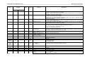
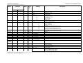
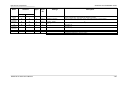
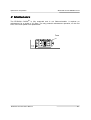
1
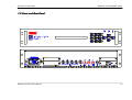
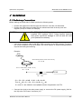
EPSILON CLOCK
MODEL EC3S
USER’S MANUAL
95 Methodist Hill Drive
Rochester, NY 14623
Phone: US +1.585.321.5800
Fax: US +1.585.321.5219
3 Avenue du Canada
91974 Les Ulis, France
Phone: +33(0)1.64.53.39.80
Fax: +33(0)1.64.53.39.81
www.spectracomcorp.com
www.spectracom.fr
Ref. Number 4573-D0
Manual Revision D0
20 June 2008
Copyright © 2008 Spectracom Corporation. The contents of this publication may not be
reproduced in any form without the written permission of Spectracom Corporation.
Specifications subject to change or improvement without notice.
Spectracom, EPSILON CLOCK, NetClock, Ageless, TimeGuard, TimeBurst, TimeTap,
LineTap, MultiTap, VersaTap, and Legally Traceable Time are Spectracom registered
trademarks. All other products are identified by trademarks of their respective
companies or organizations. All rights reserved.
SPECTRACOM LIMITED WARRANTY
LIMITED WARRANTY
Spectracom warrants each new product manufactured and
sold by it to be free from defects in software, material,
workmanship, and construction, except for batteries, fuses, or
other material normally consumed in operation that may be
contained therein AND AS NOTED BELOW, for five years after
shipment to the original purchaser (which period is referred to
as the “warranty period”). This warranty shall not apply if the
product is used contrary to the instructions in its manual or is
otherwise subjected to misuse, abnormal operations, accident,
lightning or transient surge, repairs or modifications not
performed by Spectracom.
The GPS receiver is warranted for one year from date of
shipment and subject to the exceptions listed above. The
power adapter, if supplied, is warranted for one year from date
of shipment and subject to the exceptions listed above.
THE TIMEVIEW ANALOG CLOCKS ARE WARRANTED FOR
ONE YEAR FROM DATE OF SHIPMENT AND SUBJECT TO
THE EXCEPTIONS LISTED ABOVE.
THE
TIMECODE
READER/GENERATORS
ARE
WARRANTED FOR ONE YEAR FROM DATE OF SHIPMENT
AND SUBJECT TO THE EXCEPTIONS LISTED ABOVE.
THE WIRELESS CLOCK SYSTEM TRANSMITTERS AND/OR
TRANSCEIVERS AND CLOCKS ARE WARRANTED FOR
TWO YEARS FROM DATE OF SHIPMENT AND SUBJECT
TO THE EXCEPTIONS LISTED ABOVE.
THE
EPSILON
CLOCKS,
BOARDS,
AND
SYNCHRONIZATION UNITS ARE WARRANTED FOR TWO
YEARS FROM DATE OF SHIPMENT AND SUBJECT TO THE
EXCEPTIONS LISTED ABOVE.
The Rubidium oscillator, if supplied, is warranted for two years
from date of shipment and subject to the exceptions listed
above.
All other items and pieces of equipment not specified above,
including the antenna unit, antenna surge suppressor and
antenna pre-amplifier are warranted for 5 years, subject to the
exceptions listed above.
WARRANTY CLAIMS
Spectracom’s obligation under this warranty is limited to infactory service and repair, at Spectracom’s option, of the
product or the component thereof, which is found to be
defective. If in Spectracom’s judgment the defective condition
in a Spectracom product is for a cause listed above for which
Spectracom is not responsible, Spectracom will make the
repairs or replacement of components and charge its then
current price, which buyer agrees to pay.
Spectracom shall not have any warranty obligations if the
procedure for warranty claims is not followed. Users must
notify Spectracom of the claim with full information as to the
claimed defect. Spectracom products shall not be returned
unless a return authorization number is issued by Spectracom.
Spectracom products must be returned with the description of
the claimed defect and identification of the individual to be
contacted if additional information is needed. Spectracom
products must be returned properly packed with transportation
charges prepaid.
Shipping expense: Expenses incurred for shipping
Spectracom products to and from Spectracom (including
international customs fees) shall be paid for by the customer,
with the following exception. For customers located within the
United States, any product repaired by Spectracom under a
“warranty repair” will be shipped back to the customer at
Spectracom’s expense unless special/faster delivery is
requested by customer.
Spectracom highly recommends that prior to returning
equipment for service work, our technical support department
be contacted to provide trouble shooting assistance while the
equipment is still installed. If equipment is returned without first
contacting the support department and “no problems are
found” during the repair work, an evaluation fee may be
charged.
EXCEPT FOR THE LIMITED WARRANTY STATED ABOVE,
SPECTRACOM DISCLAIMS ALL WARRANTIES OF ANY
KIND WITH REGARD TO SPECTRACOM PRODUCTS OR
OTHER MATERIALS PROVIDED BY SPECTRACOM,
INCLUDING
WITHOUT
LIMITATION
ANY
IMPLIED
WARRANTY OR MERCHANTABILITY OR FITNESS FOR A
PARTICULAR PURPOSE.
Spectracom shall have no liability or responsibility to the
original customer or any other party with respect to any liability,
loss, or damage caused directly or indirectly by any
Spectracom product, material, or software sold or provided by
Spectracom, replacement parts or units, or services provided,
including but not limited to any interruption of service, excess
charges resulting from malfunctions of hardware or software,
loss of business or anticipatory profits resulting from the use or
operation of the Spectracom product or software, whatsoever
or howsoever caused. In no event shall Spectracom be liable
for any direct, indirect, special or consequential damages
whether the claims are grounded in contract, tort (including
negligence), or strict liability.
EXTENDED WARRANTY COVERAGE
Extended warranties can be purchased for additional periods
beyond the standard five-year warranty for those products
covered under five-year warranty. Contact Spectracom no later
than the last year of the standard five-year warranty for
extended coverage.
www.spectracomcorp.com
www.spectracom.fr
Spectracom Corporation
EPSILON CLOCK MODEL EC3S
Table of Contents
1
INTRODUCTION ............................................................................................... 1-1
1.1
Inventory
1-1
1.2
Inspection
1-2
1.3
Dimensions and Weight
1-2
1.4
Basic Configuration
1-2
1.5
Terminology
1-3
1.6
Front and Rear Panel
1-5
2
INSTALLATION ................................................................................................. 2-1
2.1
Preliminary Connections
2-1
2.2
Connections Quality
2-2
2.3
Starting the Clock
2-2
2.4
Turning Off the Clock
2-4
3
SPECIFICATIONS ............................................................................................. 3-1
4
FEATURES........................................................................................................ 4-1
4.1
Frequency Output
4-1
4.2
1PPS Output
4-1
4.3
Remote Control Interface (RS232C)
4-2
4.4
TOD Output
4-2
4.5
Alarm
4-3
4.6
Mains Power Supply
4-3
4.7
DC Power Supply
4-3
4.8
GPS Antenna Input
4-4
4.9
Operating Environment
4-4
5
COMMANDS DESCRIPTION ............................................................................ 5-1
5.1
GPS setup
5-1
5.2
GPS position
5-1
5.3
Date setup
5-1
5.4
Time Reference
5-1
5.5
Local hour
5-2
5.6
TOD output setup
5-2
5.7
Display
5-2
5.8
TOD output transmission period
5-2
5.9
Alarms
5-2
5.10 Antenna Delay Correction
5-3
5.11 Functioning mode
5-3
5.12 Leap second
5-3
5.13 Clock reset
5-3
6
THE LOCAL GRAPHIC USER INTERFACE...................................................... 6-5
6.1
Functionalities
6-5
6.2
Keyboard
6-5
6.2.1
Keypad
6-5
6.2.2
Function keys
6-5
6.3
Menus
6-6
6.3.1
Connecting Menus
6-6
EPSILON CLOCK User’s Manual
iii
EPSILON CLOCK MODEL EC3S
Spectracom Corporation
6.3.2
Consulting Menus
6-6
6.3.3
Capture Menus
6-6
6.3.4
Capture confirmation
6-6
6.3.5
Menus Organization
6-7
6.4
Status Menu
6-7
6.4.1
Global Menu
6-8
6.4.2
GPS Menu
6-8
6.4.3
Menu ?
6-9
6.5
Setup Menu
6-9
6.5.1
GPS Menu
6-10
6.5.2
Time reference Menu
6-11
6.5.3
TOD Menu
6-11
6.5.4
Alarms Menu
6-12
6.5.5
1pps delay Menu
6-12
6.5.6
Mode Menu
6-13
6.5.7
Date Menu
6-13
6.5.8
Corrections Menu
6-13
6.5.9
Second Leap Menu
6-15
6.5.10
Menu Reset
6-15
7
REMOTE CONTROL INTERFACE.................................................................. 7-17
7.1
General
7-17
7.2
Protocol
7-17
7.3
Time distribution on the remote control interface
7-18
7.4
Command and Request List
7-19
8
MAINTENANCE................................................................................................. 8-1
iv
EPSILON CLOCK User’s Manual
Spectracom Corporation
EPSILON CLOCK MODEL EC3S
1 Introduction
The EPSILON CLOCK® family of products provides solutions to a wide variety of users for
applications involving time, frequency, and synchronization. The Model EC3S clock is highly
accurate, stable frequency sources operating from GPS input.
The relative accuracy of clock frequency is 1.10-12 in relation to the international frequency
definition. Time setting is accurate to less than 100 ns in relation to UTC (GPS) time.
The initial configuration may be changed by the user through the local user interface or through
the remote control interface (described herein).
The clock has autonomous control of GPS system integrity features (TRAIM) and rejects
defective satellites.
The time reference thus obtained is processed by efficient algorithms that control the built-in
oscillator, which generates inner frequency and time signals. The clock continues to distribute
time and frequency signals even if the GPS input signal is lost. Furthermore, “learning” from its
behavior in different situations (effects attributed to aging and to temperature variations) while
the GPS reference signal is present, the frequency driver improves on the accuracy of time and
frequency distribution when the GPS signal is lost.
Most of the EPSILON CLOCK's functions are software controlled. At start-up, the clock carries
out a series of automatic tests, including hardware tests and verification of the built-in oscillator's
stability ,before making an initial coarse adjustment to the distributed frequency. After half an
hour, the frequency accuracy approaches 5.10-11 and the time setting is accurate to within 1µs
of UTC time.
The standard EPSILON CLOCK® MODEL EC3S clock is used to generate, maintain, and
provide the following:
•
•
A synchronized UTC (GPS) time reference. The clock distributes a 1PPS signal and a
time code message corresponding to this signal.
A frequency reference: four 10 MHz outputs.
The clock is powered by AC or DC power supplies. A remote control interface provides
information on clock status and allows the user to send initialization and configuration
commands. The working status of the clock is reported locally using the three LED indicators on
the front panel of the machine.
The relay contact output of the machine is closed in the event of hardware failure (the closure
on hardware or software failure is a factory setting).
The EPSILON CLOCK® is fully automatic. It requires no field service for a period of 10 years.
1.1 Inventory
Before installing your Spectracom product, please verify that all material ordered has been
received. If there is a discrepancy, please contact Spectracom Customer Service. Customer
EPSILON CLOCK User’s Manual
1-1
EPSILON CLOCK MODEL EC3S
Spectracom Corporation
service is available by telephone at +33 (0) 1.64.53.39.80 (France), or +1.585.321.5800 (United
States). Updated contacts information are available on web site, see “Support” page.
CAUTION:
Electronic equipment is sensitive to Electrostatic
Discharge (ESD). Observe all applicable ESD
precautions and safeguards when handling the
Spectracom equipment.
NOTE: If equipment is returned to Spectracom, it must be shipped in its original packing
material. Save all packaging material for this purpose.
1.2 Inspection
Unpack the equipment and inspect it for damage. If any equipment has been damaged in
transit, please contact Spectracom Customer Service. Customer service is available by
telephone at +33 (0) 1.64.53.39.80 (France), or +1.585.321.5800 (United States). Updated
contacts information are available on web site, see “Support” page.
1.3 Dimensions and Weight
Height
Width
Depth
Weight
2 U * 89 mm
19’’ * 483 mm
* 340 mm
< 7 kg
Configuration
1.4 Basic Con
figuration
This document is applicable to the EPSILON CLOCK® Model EC3S equipped with OCXO or
Rubidium oscillators. In its basic configuration, the EPSILON CLOCK® Series 3S is equipped
with:
-
1-2
1 GPS antenna input,
1 main power supply input (90 to 265V / 48 to 63 Hz),
1 DC power supply input (18 to 32 VDC),
4 x 10 MHz outputs (>10 dB / 50 Ω),
1 1PPS output (TTL / 50 Ω),
1 time code output (RS232C),
1 alarm output (relay contact),
1 remote control interface (RS 232C).
EPSILON CLOCK User’s Manual
Spectracom Corporation
EPSILON CLOCK MODEL EC3S
1.5 Terminology
GPS
OCXO
Rb
S/A
TRAIM
UTC
1PPS
1 PPS driver
TOD
Holdover
Autonomy
Reliability
Frequency driver
Reference input
IERS
Global Positioning System
Oven Controlled XTAL (Crystal) Oscillator
Rubidium oscillator
Selective Availability
Time Receiver Autonomous Integrity Monitoring
Universal Time Coordinated
One Pulse Per Second
Pulse signal obtained through division of the frequency driver
Time Of Day
If the reference input signal is lost, the EPSILON CLOCK® maintains the
generation of information and of time and frequency signals.
On user request, the EPSILON CLOCK® maintains the generation of time
and frequency signals without using the reference input.
Concerns the positioning mode of the antenna. In automatic mode, the
EPSILON CLOCK® calculates the position of the antenna and, after
testing the result, imposes the reliable position on the internal GPS
receiver. The receiver therefore functions in GPS 0D reception mode. The
EPSILON CLOCK® is synchronized by following at least one satellite.
Frequency signal generated by the built-in oscillator.
Time and frequency source used by the EPSILON CLOCK®.
International Earth Rotation Service.
EPSILON CLOCK User’s Manual
1-3
EPSILON CLOCK MODEL EC3S
1-4
Spectracom Corporation
EPSILON CLOCK User’s Manual
Spectracom Corporation
EPSILON CLOCK MODEL EC3S
1.6 Front and Rear Panel
EPSILON CLOCK User’s Manual
1-5
EPSILON CLOCK MODEL EC3S
1-6
Spectracom Corporation
EPSILON CLOCK User’s Manual
Spectracom Corporation
EPSILON CLOCK MODEL EC3S
2 Installation
2.1 Preliminary Connections
Before starting the EPSILON CLOCK®, perform the following tasks:
•
•
Position the machine so that the upper and lower air vents are not obstructed.
Position the GPS antenna outside with an unobstructed view of the sky over 360
degrees (on top of a mast, for example).
CAUTION:
•
The EPSILON CLOCK® is designed to be used with the
supplied GPS antenna ONLY. Using another antenna
may cause significant damage to the unit and will void
your Spectracom warranty.
Connect the antenna cable to the MCX GPS connector of the GPS receiver. To ensure
the correct reception of the GPS signal, the overall system of antenna/cable/protection
requires accurate gain matching.
Example:
GPS
Signals
GPS antenna placed in di rect view of the sky
G1 = 40 dB
50 m of KX13 cable (-30 dB / 100 m)
G2 = - 15 dB
EC3S
EPSILON BOARD II
Lightening protection
G3 = -1 dB
G1 + G2 + G3 = 40 dB - 15 dB - 1 dB = 24 dB
Thus: Xmin dB < G1 + G2 + G3 = 24 dB < Xmax dB
Xmin and Xmax are defined in last updated revision of application note TF2.
•
Connect the clock to the main power supply or connect the DC power supply (24V for
the 3S) to the "DC Power" connector (J2).
EPSILON CLOCK User’s Manual
2-1
EPSILON CLOCK MODEL EC3S
•
Spectracom Corporation
The main outlet and every associated extension must provide a protective path to earth
ground. The protection must not be defeated by an extension cord lacking an earth
conductor.
WARNING:
If the protective conductor's path to ground is broken or
defeated, the danger of electrical shock to the operator
may be present.
Before disconnecting the unit from the main power
supply, always switch it off. Failure to do may cause
damage that voids your Spectracom warranty.
2.2 Connections Quality
Great care must be taken in setting up the GPS Antenna and its connections. Remember that
your GPS antenna must have an unobstructed view of the sky.
The type of cable connecting the antenna to the clock and the length of the cable influence
greatly the quality of the signal reception. Cable type and length must conform to the rules
described herein.
Connections to the antenna, the accessories (surge protection, in-line amplifier) and the cable
must be weatherproofed.
An improper installation could result in problems ranging from random, intermittent loss of signal
to complete loss of GPS reference. The most common outcome is the inability to discipline the
GPS reference correctly.
2.3 Starting the Clock
Verify that the preliminary connections have been made.
If the machine is connected to the main power supply, place the ON/OFF switch in the "1"
position.
NOTE:
The ON/OFF switch does not act on the DC power supply (J2).
About 10 seconds after the power is switched on, the "1PPS" indicator will start flashing once
per second. This indicates the normal generation of the 1PPS signal by the built-in oscillator.
CAUTION:
The POWER Led will indicate red until the end of the
oscillator warm-up time (15 minutes for OCXO, 1 hour for
Rb).
For 10 seconds after clock start-up, the TOD and the
Remote Control cannot be used.
2-2
EPSILON CLOCK User’s Manual
Spectracom Corporation
EPSILON CLOCK MODEL EC3S
The two other colored indicators, "Locked" and "Power", are used to report the status of the
clock. During start-up procedures, the colors of these two indicators may be interpreted as
follows:
Locked
Power
Notes
Standard hardware
automatic test
Red
Red
Checks the basic features of the
clock
Optional hardware
test
Green
Red
Checks optional features
Period of
synchronization
Red
Green
Looking for signal emitted by GPS
satellite
Synchronization
Green
Green
The distributed time is
synchronized to UTC (GPS)
In case of hardware failure (or software failure if the corresponding factory setting is active) the
"Alarm" output (J1) is activated (closed relay contact).
The conditions for activating this output are as follows:
•
•
•
•
•
Faulty GPS receiver
Faulty frequency driver
Faulty frequency divider loop
Faulty distribution of frequency or synchronization signals
Faulty frequency or synchronization performances*
* This can be selected via the remote control interface.
If the failure occurs after the start-up sequence, both the "Locked" and "Power" indicators will be
red. In this state, the Time Of Day message is not distributed (Connector J3) and the clock will
not be synchronized to the GPS source. If this happens, contact Spectracom technical support
for more information.
If none of the indicators are lighted, the clock is not connected to the power supply.
Under normal operating conditions, the EPSILON CLOCK® will synchronize to GPS time about
3 minutes after start-up. When it is synchronized, both the "Locked" indicator will be green and
the "1PPS" indicator will flash once per second. The “Power” indicator will be red until the
Rubidium oscillator has warmed up (approximately 1 hour). In this state, the EPSILON
CLOCK® continuously provides, with UTC(GPS) reference, the following outputs:
•
•
The 1PPS output (J5) and the associated Time Of Day message output (J3)
The four frequency outputs (J6 to J9)
EPSILON CLOCK User’s Manual
2-3
EPSILON CLOCK MODEL EC3S
Spectracom Corporation
The Power led turns red in the following cases:
•
•
•
•
•
Faulty GPS receiver
Faulty frequency driver
Faulty frequency divider loop
Faulty frequency or synchronization outputs or impedances not matched
Faulty frequency or synchronization performances*
* This can be selected via the remote control interface.
2.4 Turning Off the Clock
To turn-off the EPSILON CLOCK®, place the main power switch to the 0 position and unplug
the DC (J2) power supply.
2-4
EPSILON CLOCK User’s Manual
Spectracom Corporation
EPSILON CLOCK MODEL EC3S
3 Specifications
Frequency output (10 MHz):
Accuracy (1)
Medium Term stability (2)
Rubidium
OCXO
< ±1 x 10-12 / day (typical)
< ±1 x 10-12 / day (typical)
< ±3 x 10-11 / month (typical)
< ±1 x 10⁻¹⁰ / day (typical)
Rubidium
OCXO
< ±100 ns (1σ)
< ±100 ns (1σ)
< 2 µs
< 7 µs
Time output (1PPS):
Accuracy
Holdover Mode after 1 day (2)
(1): Average over 24 hours when GPS locked after 3 months of continuous operation
(2): Without GPS, constant temperature after 3 months of continuous operation
EPSILON CLOCK User’s Manual
3-1
EPSILON CLOCK MODEL EC3S
3-2
Spectracom Corporation
EPSILON CLOCK User’s Manual
Spectracom Corporation
EPSILON CLOCK MODEL EC3S
4 Features
4.1 Frequency Output
Connectors:
J6, J7, J8, J9 BNC Female
Pin settings:
Core:
Sine-wave signal
Frequency:
Level:
10 MHz
> 10 dBm load 50 Ω (typical 13 dBm)
Ground: Electrical ground of the clock
4.2 1PPS Output
Connector J5:
BNC Female
Pin settings:
Core:
Period:
Active edge:
Pulse duration:
High-level:
Low-level:
Rising edge duration:
Periodic pulse
1s
Rising
100µs ± 10µs
> 2.4 V load 50Ω
< 0.8 V load 50Ω
< 20 ns load 50Ω
Ground: Electrical and mechanical ground of the clock
EPSILON CLOCK User’s Manual
4-1
EPSILON CLOCK MODEL EC3S
Spectracom Corporation
4.3 Remote Control Interface (RS232C)
Serial port parameters:
Protocol / syntax / format of messages:
Data:
Order of bytes emitted:
9600 bps, 8 bits, 1 stop bit, odd parity
Refer to the remote control interface
Binary (two's complement)
Most significant bytes first
Connector J4: Mini Din 8 pins female
Pin settings:
Pin
1
2
3
4
5
6
7
8
Setting
Reserved
Reserved
Message Output (RS 232C)
Electrical and mechanical ground
Message Input (RS232C)
NC
NC
Reserved
4.4
TOD Output
Time Of Day message output:
Output:
ASCII, 9600 bps, 8 bits, 1 stop bit, odd parity.
Protocole:
<Message> CR
LF
Format*:
Day/Month/Year
Hour: Minute: Second Source
e.g.: 20/03/1996_21:02:05U
Format*:
Month/Day/Year
Hour: Minute: Second Source
e.g.: 11/12/1996_18:14:38L
Format*:
Day of Year/Year
Hour: Minute: Second
e.g.: 317/1996_18:16:20 L
Source
Format*:
MJD** - Integer part Hour: Minute: Second
e.g.: _ _ _ _ _ _50399.18:20:50_U
Source
Format*:
MJD**
Source
e.g.: _ _ _ _ _ _50399.762130_L
The "Source" byte holds one ASCII character which codes the reference of the time chosen
N
No reference
U
UTC reference
G
GPS reference
L
Local time
M
Manual
Maximum output period*:
1 message per second
Output synchronization:
sent at 200 ms ±100 ms after the 1PPS signal.
*
4-2
Programmable through the remote control interface.
EPSILON CLOCK User’s Manual
Spectracom Corporation
EPSILON CLOCK MODEL EC3S
** Modified Julian Day
Connectors:
J3
Mini Din 6 pins Female
Pin settings:
Pin
1
2
3
4
5
6
Setting
Reserved
NC
Electrical and mechanical ground
Electrical and mechanical ground
Message Output (RS232C)
NC
4.5 Alarm
Connector:
Resistive Contact Rating:
Ground:
J1 BR2 Female
30 VA / 250 V
Mechanical ground of the clock
4.6 Mains Power Supply
Mains power connector CCE22 with ON/OFF switch.
Input voltage:
90 to 265 V / 48 to 63 Hz
Fuses:
2 x 250 V - 1A TD (Time Delay)
Consumption:
OCXO type oscillator : < 25 W typical
Rb type oscillator:
< 60 W typical
4.7 DC Power Supply
Input power (VDC):
Series 3S:
18 to 32V
Consumption: < 60 W typical
Protection against polarity inversion.
Protection against short-circuit: polyswitch ensures the isolation of the clock in relation to the DC
power supply in the event of a short-circuit of the clock's power supply.
EPSILON CLOCK User’s Manual
4-3
EPSILON CLOCK MODEL EC3S
Spectracom Corporation
Connector J2: Min Din 7 pins Female
Pin settings:
Pin
1
2
3
4
5
6
7
Setting
VDC
VDC
VDC
VDC
Electrical Ground
Electrical Ground
Electrical Ground
4.8 GPS Antenna Input
Connector "Antenna": TNC Female 50Ω
Core: GPS Signal Input (L1)
Output power supply of the active antenna
Voltage:
5V
Current:
75 mA max.
"Fold Back" protection:
The power supply is cut in the event of a short-circuit in the
antenna input.
Ground:
Electrical and mechanical ground of the clock
4.9 Operating Environment
Operating temperature:
Storage temperature:
Relative humidity:
EMC:
4-4
0 to +50°C
- 40°C to 85°C
90 % without condensation
In accordance with EN50081 and EN50082
EPSILON CLOCK User’s Manual
Spectracom Corporation
EPSILON CLOCK MODEL EC3S
5 Commands Description
5.1 GPS setup
This command defines the clock functioning mode with regards to the GPS signals received.
Three modes are available: Automatic, Manual, or Mobile.
The Automatic mode is the default mode during the clock initialization. In this mode, the clock
averages during 24 hours the antenna position supplied by the receiver in order to make it
reliable. After this period and providing that a minimum of 4 satellites were received at all times,
the position is fixed and the clock requires only one satellite for time transfer. This 24 hour
reliability procedure of the position is initialized every time the clock is switched on and is
maintained as long as a minimum of 4 satellites are not received continuously.
The manual mode allows the user to instantaneously force the GPS receiver to function in one
satellite mode. The user is required to enter the date and the geographic position of the
antenna.
The Mobile mode is useful when the clock is moved while functioning. This command prevents
the GPS receiver from switching to the 1 satellite mode. It is therefore necessary in this case to
receive a minimum of 4 satellites continuously to ensure a good disciplining of the frequency
source.
5.2 GPS position
This command allows the initialization of the antenna position. This is necessary in Manual
mode.
5.3 Date setup
This command initializes the date of the clock’s GPS receiver. This, associated with the
initialization of position, when possible, accelerates the tracking procedure of the GPS satellites.
5.4 Time Reference
This command also allows the user to define which time reference is used. The two possibilities
are as follows:
•
•
The Universal Time Coordinated,
The GPS Atomic Time.
The difference between these two time references is equal to a whole number of seconds,
which changes with every leap second insertion in the UTC reference.
The GPS Atomic Time reference is recommended when the user's application requires a
perfectly continuous time reference. In effect, the GPS Atomic Time is not subject to leap
second insertion.
EPSILON CLOCK User’s Manual
5-1
EPSILON CLOCK MODEL EC3S
Spectracom Corporation
5.5 Local hour
Using this command, the user may shift the hour transmitted by the GPS clock. This shift
corresponds to a whole number of hours and minutes (such as a correction for DST).
output
5.6 TOD out
put setup
This command allows the user to modify the contents of the periodical messages transmitted by
the clock on the TOD output. In standard mode, the default message transmitted contains the
current date and hour according to the codes provided herein. In diagnostic mode, the message
transmitted contains information regarding the disciplining of the frequency driver to the GPS
reference. This mode is used by the manufacturer during the “good” working verification phases.
5.7 Display
This command defines the format of the hour transmitted by the TOD message and displayed
on the front panel display screen if this option was chosen.
The five formats available are as follows:
•
•
•
•
•
Day / Month / Year
Month / Day / Year
Day of year / Year
MJD
MJD integer part
Hour: Minute: Second
Hour: Minute: Second
Hour: Minute: Second
(Modified Julian Day)
Hour: Minute: Second
With this command, the user defines whether the output of the hour is issued from the UTC or
GPS time reference, or from the local hour with the programmed shift.
5.8 TOD output transmission period
This command defines the transmission period to the TOD message on the corresponding
special link. This period is quantified in seconds; the value 0 inhibits permanently the
transmission of the message.
Alarms
5.9 Al
arms
If the GPS input signal is lost, the clock's internal oscillator is no longer disciplined. The
frequency accuracy and the distributed synchronization start to degrade slowly according to the
ageing of the oscillator.
Using the alarms limits commands, the user may define the accuracy limits outside of which the
output signals are deemed invalid. These limit values are in the form of a time difference for the
1 PPS and in the form of a relative frequency difference for the frequency outputs.
When these limit values are reached, a fault is generated and the contact relay is closed.
In addition, the user may activate the squelch of the frequency outputs. These outputs are
disabled in the same way the alarm is activated.
5-2
EPSILON CLOCK User’s Manual
Spectracom Corporation
EPSILON CLOCK MODEL EC3S
5.10 Antenna Delay Correction
The cable between the antenna and the clock generates a propagation delay of the GPS signal.
This delay corresponds to a time shift of the synchronizing signal. This time shift can be
compensated for using this command. The correction is entered in nanoseconds, and the value
corresponding to the delay is linked to the type of cable and its length. As a general rule of
thumb, the value for the delay of a coaxial cable is 5 to 6 nanoseconds per meter.
5.11 Functioning mode
The initial functioning mode of the clock is always synchronized on the GPS reception.
However, the user could configure the clock in off-line mode. This stops the disciplining of the
driver frequency and of the 1PPS. In the off-line mode, the user has the manual setup function
available.
I
5.12 Leap second
The UTC time reference, maintained by the GPS clock, is subject to leap second corrections,
the purpose of which is to maintain the difference between the atomic time represented by UTC
and the astronomic time. These corrections decided by the IERS are published in Bulletin C and
D.
If the time reference used by the clock is UTC, these corrections are automatically made in real
time provided the GPS signal is received correctly. This command allows the clock to maintain a
reliable time reference by programming in advance the leap second correction, ensuring it will
be applied even in the case of loss of GPS signal input.
This command does not apply to the other time references.
5.13 Clock reset
This command generates the re-initialization of the clock.
EPSILON CLOCK User’s Manual
5-3
EPSILON CLOCK MODEL EC3S
5-4
Spectracom Corporation
EPSILON CLOCK User’s Manual
Spectracom Corporation
EPSILON CLOCK MODEL EC3S
6 The Local Graphic User Interface
6.1 Functionalities
The UI manages the keyboard and the screen of the clock. It allows the following choices:
- Sequenced menu,
- Data consulting,
- Data capture,
- Controlling selection to execute ,
- Permanent display of some states of the system.
6.2 Keyboard
The UI keyboard consists of:
- A keypad including the "C" and "." keys,
- A set of 5 keys to move the cursor or to validate.
6.2.1 Keypad
The 0 to 9 keys are reserved for the capture of the digital fields.
The key C is used to select the data among a multiple choice.
The key '.' is not used in this application.
6.2.2 Function keys
The key functions are as follows:
→
Set the cursor on the next capture field, or
display the next page
←
Set the cursor on the previous capture field,
or display the previous page
↑
Go back to the previous menu. The current
capture is not confirmed
↓
Go to the next menu
V
Confirmed the capture of the current menu
EPSILON CLOCK User’s Manual
6-5
EPSILON CLOCK MODEL EC3S
Spectracom Corporation
6.3 Menus
Three kind of menus are provided:
- Connecting menus
- Consulting menus
- Capture menus
6.3.1 Connecting Menus
The connecting menus are access menus. To select one of these menus, use the ← → keys.
The key ↓ validates the choice. The key ↑ allows the user to go back to the previous menu.
6.3.2 Consulting Menus
These menus may have many pages. You may use the "scrolling" mode page per page with the
← → keys. The key ↑ allows the user to go back to the previous menu. There is no circle cycle
at the end of it.
6.3.3 Capture Menus
The user indicates a functioning parameter of the clock: digital length or other proposed option.
The digital values are captured with the 0 to 9 keys.
The choice is done with the C key to select the character [ ] around the chosen option.
6.3.4 Capture confirmation
The capture is validated by using the V key, if there were some modifications. The user receives
the following indications:
- OK
The capture is successful
- ERR The capture is not successful
- REM The UI is inactive. The clock runs in remote control mode (REMOTE)
To exit the menu, press the key offered.
6-6
EPSILON CLOCK User’s Manual
Spectracom Corporation
EPSILON CLOCK MODEL EC3S
6.3.5 Menus Organization
TEKELEC TEMEX
Time message
Status
GLOBAL
GPS
Setup
?
GPS
Time reference
TOD
Alarms
Tresholds
Tracking Position Date
Date format
Option
1 p p s d e la y
Output
Frequencies
Mode
Date Corrections Leap Second Reset
Frequency
1pps
Seconde
Serial line
6.4 Status Menu
This allows access to the states consultation menu of the clock.
.Global
STATUS
.GPS
.?
Active keys : ←, →, ↑, ↓.
To select the menu, use the keys : ←, →.
The ↓ key allows the user to select the under menu.
The ↑ key allows the user to go back to the upper menu.
EPSILON CLOCK User’s Manual
6-7
EPSILON CLOCK MODEL EC3S
Spectracom Corporation
6.4.1 Global Menu
This menu gives global information about the functioning of the clock. The sub-menus are the
following :
Reference input : OK
Synchronization : OK
← Internal 1pps : OK
Output freq : OK
Hardware : OK
Internal Freq : OK
→
Output 1pps : OK
Option output :OK →
← Phase alarm
: OK
Frequency alarm : OK
Reference input (GPS) of the material, of the
synchronization, and of the internal frequency
state.
Internal 1pps, frequency outputs and option
output state.
Display of the phase alarms and frequency alarm.
→
← Clock control : Local
Functioning mode of the UI
Local : keyboard
Remote : Remote control
Active keys : ←, →, ↑.
To select the menu, use the keys : ←, →.
The ↑ key allows the user to go back to the upper menu.
6.4.2 GPS Menu
This menu gives information about the GPS reception. The sub-menus are the following :
Receiver status : OK
Antenna
: connected
Mode : 3D
→
GPS receiver status of the clock.
← Lat : 48°41'33"827 N Hgt : +00196.00m
Lon :002°12'58"984 E
→
Calculated Position by the GPS antenna.
← Position hold : No
Sigma
: 00050 ns
Reliability state of the position hold
Estimated error on the GPS 1 PPS precision .
→
N° of the GPS satellites followed.
←Sat Id :#03 #12 #23 #31 #04 #19 31 45
Sat SNR :050 042 045 046 049 045 040 042 Reception level for each satellite.
Active keys : ←, →, ↑.
To select the menu, use the keys : ←, →.
The ↑ key allows the user to go back to the upper menu.
6-8
EPSILON CLOCK User’s Manual
Spectracom Corporation
EPSILON CLOCK MODEL EC3S
6.4.3 Menu ?
This menu gives information about the based configuration of the clock:
Software version : 07.01
Series :3
Input opt : GPS
Output option : STANAG →
Software Version .
Synchronization on GPS / Output option.
←Frequencies : 5MHz
DC input : 24V
Given Frequencies .
External DC power supply
→
←Pilot
: Rubidium high perf.
Alarm output : Hardware or Software
→
Kind of frequency pilot.
Alarm in case of Hardware or Software default
Active keys : ←, →, ↑.
To select the menu, use the keys : ←, →.
The ↑ key allows the user to go back to the upper menu.
6.5 Setup Menu
This menu allows the user to access sub-menu to configure the clock.
SETUP
.GPS .Time reference .TOD
←
.Option
.1pps delay
←
.Correction
.Alarms
→
Date
→
.Mode
Leap second
.Reset
Active keys : ←, →, ↑, ↓.
To select the menu, use the keys : ←, →.
The ↓ key allows the user to select the under menu.
The ↑ key allows the user to go back to the upper menu.
For each menu, the default configuration is the one written in different characters in the
following chapter.
The Option menu may be selected if the G704 option is in the clock.
EPSILON CLOCK User’s Manual
6-9
EPSILON CLOCK MODEL EC3S
Spectracom Corporation
6.5.1 GPS Menu
This menu may be chosen if the SLAVED mode is selected
This allows the user to set up the GPS receiver mode :
.Tracking
GPS receiver setup
.Position
.Date
Select the sub-menu with the keys → ← et ↓.
Tracking :
Tracking mode : [Auto] Fix Mobile
GPS tracking mode : Automatic, Manual or
Mobile.
Select the tracking mode Automatic, Manual, or mobile with the keys C and V to confirm the
choices
Position :
Lat : 48°41'33"827 N Hgt : +00196.00m
Lon :002°12'58"984 E
Setup of the GPS Antenna Position.
The digital keys are used to set this with the key C and the keys ← and →. The position setup is
necessary only in Fix mode.
Date :
Date : 10/24/1997 (mm/dd/yyyy)
Time : 12 :33 :46
(hh :mm :ss)
Date & time setup.
The digital keys are used to set this with the key C and the keys ← and →. The date setup is
necessary only in Fix mode.
6-10
EPSILON CLOCK User’s Manual
Spectracom Corporation
EPSILON CLOCK MODEL EC3S
6.5.2 Time reference Menu
This menu may be chosen if the SLAVED mode is selected
This allows the user to select the time reference :
Time reference : GPS [UTC]
Local time offset from UTC : +00h00mn
Time reference GPS or UTC
Time offset from UTC.
The offset time is active if the UTC reference is selected. This function allows the user to select
local time.
Active keys : ←, →, ↑, C, keypad and V.
The selection is done with the C key.
The offset time is selected with the keypad.
The V key allows the user to validate the capture.
The ↑ key allows the user to go back to the upper menu.
6.5.3 TOD Menu
This menu allows the user to set up the time format of the TOD output.
TOD SETUP
.Date format
.Serial line
Select the under menu with the keys → ← and ↓.
Date format :
Date format : [Day/Month/Year]
Distribution & display format of the time message
.
Serial line:
TOD output period : 000001s
Output message : [TOD] Factory message
TOD output period.
The Factory message may be used only by
Spectracom in Debug mode .
Active keys: ←, →, ↑, C, keypad and V.
The selection is done with the C key.
The TOD output period is selected with the keypad.
The V key allows the user to validate the capture.
EPSILON CLOCK User’s Manual
6-11
EPSILON CLOCK MODEL EC3S
Spectracom Corporation
The ↑ key allows the user to go back to the upper menu.
6.5.4 Alarms Menu
This allows the user to setup activating values of the phase and frequency alarms.
ALARM SETUP
.Thresholds
.Output frequencies
Select the under menu with the keys → ← and ↓.
Thresholds :
Phase alarm limit
Frequency alarm limit
: 0000001µs
: 00100e-9
Phase alarm threshold
Frequency alarm threshold
Phase alarm at 0 let it in active.
The frequency alarm at 0 let it active just after the GPS reception loss.
Output frequencies :
Out. freq. squelch on alarm : Yes [No]
The user may cut off the frequency outputs in
case of alarms squelch .
Active keys : ←, →, ↑, C, keypad and V.
The selection is done with the C key.
The alarm threshold is selected with the keypad.
The V key allows the user to validate the capture.
The ↑ key allows the user to go back to the upper menu.
6.5.5 1pps delay Menu
This menu may be chosen if the SLAVED mode is selected
The 1PPS delay is the delay due to the GPS antenna cable.
1PPS delay: 000000 ns
Active keys : ←, →, ↑, C, keypad and V.
The delay is selected with the keypad.
The V key allows the user to validate the capture.
The ↑ key allows the user to go back to the upper menu.
6-12
EPSILON CLOCK User’s Manual
Spectracom Corporation
EPSILON CLOCK MODEL EC3S
6.5.6 Mode Menu
The user may select the functioning mode of the clock: slaved on GPS or off-line (non-slaved).
Slaving on GPS input : [yes] no
Active keys: C, V and ↑.
If the [Yes] is selected with the C key and followed by the V key, the slaving on GPS is
validated.
If the [No] is selected and followed by the V key, the slaving is in off line mode.
The ↑ key allows the user to go back to the upper menu.
6.5.7 Date Menu
This menu may be chosen if the OFF LINE mode is selected
This allows the manual time setup of the clock. The time capture format is the same as the time
given.
Date : 11/09/1997 (dd/mm/yyyy)
Time : 16 :23 :00
(hh :mm :ss)
Active keys : ←, →, C, V, ↑, ↓, and keypad.
The selection is done with the C key.
The V key allows the user to validate the capture.
The ↑ key allows the user to go back to the upper menu.
6.5.8 Corrections Menu
This menu is optional and may be chosen if the OFF-LINE mode is selected.
Frequency and 1PPS corrections are optional
This allows the user to access to the correction sub-menu .
.Frequency
CORRECTIONS
.1PPS
.second
Active keys : ←, →, ↑, ↓.
To select the menu, use the keys: ←, →.
EPSILON CLOCK User’s Manual
6-13
EPSILON CLOCK MODEL EC3S
Spectracom Corporation
The ↓ key allows the user to select the under menu.
The ↑ key allows the user to go back to the SETUP menu.
Frequency :
The frequency correction of the pilot. The capture corresponds to ∆f/f and is independent from
the pilot frequency.
Frequency correction : ±00000e-12
Active keys: V, ↑ and keypad.
The V key allows the user to validate the capture.
The ↑ key allows the user to go back to the CORRECTIONS menu.
1 PPS:
Phase correction of the 1pps.
1pps correction : ±000000.0 µs
Active keys: C, V, ↑ and keypad.
The selection is done with the C key.
The V key allows the user to validate the capture.
The ↑ key allows the user to go back to the CORRECTIONS menu.
Second :
Displays the current time and allows the user to correct it ± 1 second.
11/01/1997 10 :30 : 00 UTC
second correction : [+1 sec.] -1 sec.
Active keys: C, V and ↑.
The C key selects +1 second or -1 second.
The V key allows the user to validate the capture.
The ↑ key allows the user to go back to the CORRECTIONS menu.
6-14
EPSILON CLOCK User’s Manual
Spectracom Corporation
EPSILON CLOCK MODEL EC3S
6.5.9 Second Leap Menu
This function allows the user to program a positive or negative leap second when the time
reference is UTC.
Leap second : [Positive] Negative No
Day of year : 001 Year : 1992
Active keys : ←, →, ↑, ↓, C, V and keypad.
The C key selects the application way of the leap second.
The keypad allows the capture of the date.
The V key allows the user to validate the capture.
The ↑ key allows the user to go back to the SETUP menu.
6.5.10 Menu Reset
This allows the user to reset the clock.
Do you want to reset the clock now ?
Yes [No]
Active keys: C and V.
EPSILON CLOCK User’s Manual
6-15
EPSILON CLOCK MODEL EC3S
7-16
Spectracom Corporation
EPSILON CLOCK User’s Manual
Spectracom Corporation
EPSILON CLOCK MODEL EC3S
7 Remote Control Interface
7.1 General
The remote control interface allows remote configuration and remote status reporting of the
clock. The RS232C connection operates at 9600 bps and is set to 8 bits, 1 stop bit, and odd
parity.
7.2 Protocol
The protocol used is Master (Host) / Slave (EPSILON CLOCK®) with a systematic reply to all
messages. The following exceptions apply (for which no reply is expected):
•
•
The time code message sent periodically
The reset clock command
All messages start with the "STX" character and end with the "ETX" character.
e.g.: <STX> <Message> <ETX>
The characters “ STX ”, “ ETX ” or “ DLE ” to be sent within a message should be escaped
(prefixed) by the "DLE" character.
Each message contains four distinct sections:
•
•
•
•
The message “ID” (this identifies the type of message being sent):
The count of the number of data bytes in the message (CNT),
The data bytes (DATA(*)) of the message,
The checksum: calculated by performing an exclusive OR on all the consecutive
characters in the message (ID + CNT + DATA)
e.g.:
<Message> = <ID> <CNT >
Number of bytes
1
1
<DATA(*)>
N
<CS>
1
(*): The encoding format of the DATA is based on “MOTOROLA big Endian” type (integer, long,
float, and double data must be sent or received with the MSB first).
NOTE: The maximum length of the <DATA> section is 255 bytes.
Messages belong to one of three categories:
• Queries (requests for information from the EPSILON CLOCK®)
• Commands (functions that initialize or configure the EPSILON CLOCK®)
• Error Messages (returned by the clock if errors are detected in the Queries or
Commands sent by the user)
When a user sends a message to the EPSILON CLOCK®, it replies within the current second.
This reply, or acknowledgement, is formatted as follows:
•
The format of the message is identical to the message sent by the user
EPSILON CLOCK User’s Manual
7-17
EPSILON CLOCK MODEL EC3S
•
•
Spectracom Corporation
The contents of sections <ID> and <CNT> are identical to those sent by the user
The content of the <DATA > section:
o Is identical to that sent by the user if the message was a Command
o Contains the information supplied by the clock, if the message was a Query
The acknowledgement to a Command is an exact copy of the message sent.
The reply to a Query is the copy of the Query message with the <DATA> section completed by
the EPSILON CLOCK®. In a query, the <DATA> field is not taken into account by the EPSILON
CLOCK® command interpreter.
An Error message is generated by the clock if one of the following errors occurs:
• The message contains an unknown ID
• The number of bytes in the <DATA> section does not correspond to the <CNT> value
• An overflow is detected in a parameter within the <DATA> section
7.3 Time distribution on the remote control interface
The time message is transmitted to the remote control interface. The format and the output TOD
are selected by the "display" function. The transmission is synchronous with the 1pps.
Format 1:
ID:
193
CNT: 8
DATA: day/month/year/hour/min/sec/source
Format 2:
ID:
194
CNT: 8
DATA: day/month/year/hour/min/sec/source
Format 3:
ID:
195
CNT: 8
DATA: Day of Year/year/hour/min/sec/source
Format 4:
ID:
196
CNT: 9
DATA: MJD/source
Format 5:
ID:
197
CNT: 8
DATA: MJD integer part/hour/min/sec/source
The "Source" byte holds an ASCII character, which codes the time reference:
N
U
G
L
M
7-18
No reference
UTC reference
GPS reference
Local time
Manual
EPSILON CLOCK User’s Manual
Spectracom Corporation
EPSILON CLOCK MODEL EC3S
7.4 Command and Request List
Designation
Command ID
Request ID
Useful bytes n°
Status
---
80
37
Version
---
67
10
Date setup
4
68
7
GPS setup
10
74
19
Local Time
7
71
2
Display
13
77
2
Emission Time of the TOD
2
66
4
Serial Line Configuration
1
65
1
Antenna delay Correction
8
72
4
Leap Second
9
73
6
Alarms limits
14
78
10
Mode (slaved or off line)
15
79
1
Manual time setting
17
81
7
Frequency correction
20
84
4
1pps correction
19
83
4
correction ± 1 second
21
85
1
Local/Remote control
18
82
1
Reset
16
---
0
The tables that follow contain the format of the commands and the requests.
EPSILON CLOCK User’s Manual
7-19
EPSILON CLOCK MODEL EC3S
7-20
Spectracom Corporation
EPSILON CLOCK User’s Manual
Spectracom Corporation
Name
Status
EPSILON CLOCK MODEL EC3S
Identifier
Query
Command
80
-
Bytes
Byte
No.
37
0
1
Settings
b0 = 1
b0 = 0
b1 to b7
b0 = 1
b0 = 0
b1 = 1
b1 = 0
b2 = 1
b2 = 0
b3 = 1
b3 = 0
b4 = 1
b4 = 0
b5 = 1
Status
80
-
37
1
b5 = 0
b6 = 1
b6 = 0
2
b7 = 1
b7 = 0
b0 = 1
b0 = 0
b1 = 1
b1 = 0
b2 = 1
b2 = 0
b3 = 1
b3 = 0
3
EPSILON CLOCK User’s Manual
Description
Clock is synchronized to the reference input (GPS)
Clock is not synchronized (the clock is in hold over mode after the loss of the reference input
signal).
Reserved bits.
Reference input 1 PPS failure.
Reference input 1 PPS operational.
Frequency driver failure.
Frequency driver operational.
1PPS driver failure.
1PPS driver operational.
Failure in at least one standard frequency output.
All the standard frequency outputs are operational.
1PPS output failure.
1PPS output operational.
Phase limit alarm : loss of synchronization, programmed phase-limit exceeded.
Phase limit not exceeded.
Frequency or limit alarm : loss of synchronization (if the programmed limit is set to 0) or loss of
synchronization and limit exceeded or synchronization period too short to provide the programmed
frequency limit.
Programmed frequency or limit not exceeded : the clock is synchronized during a period of time
sufficient enough to provide the frequency inside the programmed limit or the loss of
synchronization is not sufficiently long to exceed the programmed limit.
Optional output board failure.
Optional output board operational.
EPSILON CLOCK® hardware failure.
EPSILON CLOCK® hardware operational.
Reserved
Antenna not connected.
Antenna connected.
Antenna short circuit alarm.
No antenna short circuit.
Reserved
7-21
EPSILON CLOCK MODEL EC3S
Name
Identifier
Query
Status
80
Spectracom Corporation
Bytes
Byte No.
Settings
Description
Command
-
37
4
1 or 5
4
2 or 6
-
3 or 7
5 to 20
Odd bytes (5 to 19)
GPS reception, mode 0D :
The clock is synchronized using a single satellite.
Mode set to manual positioning of the GPS antenna or after reliability testing of the GPS antenna's
coordinates in automatic positioning mode.
GPS reception mode 2D :
The clock is synchronized using 3 satellites.
This mode can only operate if the antenna positioning mode is set to mobile, or automatic (before
reliability testing and only if 3 satellites are tracked).
GPS reception mode 3D :
The clock is synchronized using 4 to 8 satellites and the antenna positioning mode is set to mobile,
or automatic (before reliability testing).
For each byte, the number of the satellite being tracked is set on bits b0 to b6. The locking to
satellite indicator is given by bit b7 (b7=0 ; locked).
Even bytes (6 to 20)
0 ... 65535
(0 to 65535 ns)
23 to 26
-324,000,000 ... 324,000,000
(-90° S ... +90° N)
-648,000,000 ... 648,000,000
(-180° W .. +180° E)
-100,000 ... 1,800,000
(-1,000 m to 1,800 m)
1
0
---
GPS receiver failure
GPS receiver operational.
Reserved
1
0
Clock diagnostic output.
TOD message output.
Period of the emission of the TOD message in seconds.
31 to 34
80
-
37
35
36
Serial port
TOD link
configuration
Period of
TOD
message
emission
Reset clock
Version
65
1
1
0
66
2
4
0 to 3
0 ... 100,000
(0 ... 100,000 sec)
--67
16
0
10
--0 to 3
4
5
6
----0 ... 255
0 ... 255
Longitude of the GPS antenna (ms).
Altitude of the GPS antenna (cm).
Stops and restarts the clock (warm-reboot).
b0 to b1
(1, 2 or 3)
7-22
Satellite 12 is locked and its SNR is 120.
Estimation of the standard deviation of the GPS 1PPS reference signal. This estimation required
the locking of at least two satellites by the clock. If only a single satellite is locked this parameter is
set to 65535, indicating that an estimation is impossible.
Latitude of the GPS antenna (ms).
21 to 22
27 to 30
Status
SNR (0 to 255) of the followed satellites.
The even byte Oi gives the SNR of the satellite indicated by the byte Oi-1
e.g. : O3 = 140 (80 HEX + 12 decimal) O4 = 120
Reserved
Software version.
Update version number.
Clock settings
1 : serie 1
2 : serie 2
Series number
3 : serie 3
EPSILON CLOCK User’s Manual
Spectracom Corporation
Name
Identifier
Query
Version
Version
EPSILON CLOCK MODEL EC3S
Bytes
Byte
No.
10
6
Settings
Command
67
67
10
7
b2= 1
b2= 0
b3 = 1
b3= 0
b4 to b6 = 7
= 4/5/6
=3
=2
=1
=0
b7 = 1
b7= 0
b0 to b1
=3
7
=2
=1
=0
=3
b2 to b3
b4
Version
Set date
67
68
4
10
7
Local time
71
7
2
Correct
antenna
cable delay
Leap second
72
8
4
8 to 9
0
1
2 to 3
4
5
6
0
1
0 to 3
73
9
6
0
1
Leap second
Set GPS
73
74
Description
9
10
EPSILON CLOCK User’s Manual
6
19
2 to 3
4 to 5
0
=2
=1
=0
=0
=1
--1 ... 31 (Days)
1 to 12 (Months)
1992 ... 2016 (Years)
0 ...23 (hours)
0 ... 59 (minutes)
0 ... 59 (seconds)
-23 ... +23 (hours)
-59 ... +59 (minutes)
0 ... 1,000 ns
1
0
1
2
1 ... 366 Days
1992 ... 2127
1
2
3
24V DC input voltage
48V DC input voltage
GPS Input
STANAG Input
No output option.
Reserved.
STANAG 4430 Output
G.704 Output.
Pulse rate output.
IRIG.B. Output
Multiple of 2048 kHz frequency .
Multiple of 1 MHz frequency .
1 MHz or 2048 kHz. (according to byte 6 / b7)
5 MHz or 4096 kHz.
10 MHz or 8192 kHz.
Reserved.
High performance Rubidium frequency driver
Standard performance Rubidium frequency driver
High-performance OCXO frequency driver
Standard performance OCXO frequency driver
Relay contact closed on hardware failure / phase limit / frequency limit.
Relay contact closed on hardware failure only.
Reserved.
Sets the GPS receiver date and time.
Difference, in hours and minutes, between local time and the clock's reference time.
Programmed difference between the distributed 1PPS signal and the built-in reference.
No leap second.
Use leap second.
Leap second addition.
Leap second subtraction.
Day of the year to be used.
Year to be used
Antenna positioning mode : Automatic
Antenna positioning mode : Manual
Antenna positioning mode : Mobile
7-23
EPSILON CLOCK MODEL EC3S
Name
Set GPS
Identifier
Query
Command
74
10
Spectracom Corporation
Bytes
Byte
No.
19
1 to 4
5 to 8
9 to 12
13 to 17
18
Settings
-324,000,000 ... 324,000,000
(-90° S ... +90° N)
-648,000,000 ... 648,000,000
(-180° W .. +180° E)
-100,000 ... 1,800,000
(-1,000 m to 1,800 m)
Remote control not active / Front panel user interface active
Remote control active / Front panel user interface not active
13
2
0
Alarm limits
78
14
10
1
0 to 3
4 to 7
0 ... 1,000 10-9
Remote
Control
7-24
15
1
9
0
81
17
7
0
1
1
2à3
4
5
6
0
82
18
Altitude (cm).
1 ... 12 (month)
1992 ... 2127 (year)
0 ...23 (hours)
0 ... 59 (minutes)
0 ... 59 (seconds)
1
0
77
79
Longitude (ms).
1
0
--1
0
1 ... 31 (days)
Display
Time
keeping
Manual time
setting
Latitude (ms).
Reserved
UTC time reference.
GPS time reference.
Day / Month / Year format
Month / Day / Year format
Day of year / Year format
MJD format
MJD format integer part /hh/mn/sec
Reserved
Phase alarm limit
0 = no phase alarm.
Frequency alarm limit
0 = alarm immediate if synchronization is lost.
No interruption of frequency output.
Frequency output interrupted if frequency limit is exceeded or in case of hardware failure.
Reserved
Functioning mode : disciplining authorised
Functioning mode : off line
Manual setting of the clock (authorised only in forced keeping mode).
1
0
0
1
2
3
4
--0 ... 1,000 µµs
8
Description
EPSILON CLOCK User’s Manual
Spectracom Corporation
Name
EPSILON CLOCK MODEL EC3S
Identifier
Bytes
Byte
No.
Query
Command
Remote
Control
1pps
correction
Frequency
correction
82
18
1
0
83
19
4
0 to 3
84
20
4
0 to 3
+1s
correction
Error
(ID = 64)
85
21
1
0
2
0
1
EPSILON CLOCK User’s Manual
Settings
Description
1
0
-2500000...2500000
Remote control not active / Front panel user interface active
Remote control active / Front panel user interface not active
Phase correction of the 1pps from -250 to +250 (active function on off line mode)
- 50000 ... 50000
(10-12)
1
0
X
Frequency correction from -5 to +5.10-8 (active function on off line mode)
Correction +1s
Correction -1s
Invalid message ID
0
1
2
Incorrect number of useful bytes
Unknown message ID
Unauthorized parameter in <DATA> section.
7-25
EPSILON CLOCK MODEL EC3S
7-26
Spectracom Corporation
EPSILON CLOCK User’s Manual
Spectracom Corporation
EPSILON CLOCK MODEL EC3S
8 Maintenance
The EPSILON CLOCK® is fully automatic and is not field-serviceable. It requires no
maintenance for a period of 10 years. The only potential maintenance operation, on the first
level, is the main power fuse replacement.
Fuse
EPSILON CLOCK User’s Manual
8-1
EPSILON CLOCK MODEL EC3S
8-2
Spectracom Corporation
EPSILON CLOCK User’s Manual
REVISION HISTORY
Revision
Level
ECN
Number
Description
A
22/06/98
B
04/08
C
26/05/08
Suppression of all references to EC3T correction of OCXO
performances
D0
20/06/08
Modification of Front and Rear Panel (sheet 1-5)
Creation
First iteration of this Spectracom documentation, converted from
Temex Sync documentation.
Spectracom Corporation
95 Methodist Hill Drive
Rochester, NY 14623
www.spectracomcorp.com
Phone: US +1.585.321.5800
Fax: US +1.585.321.5219
3 Avenue du Canada
91974 Les Ulis, France
www.spectracom.fr
Phone: +33(0)1.64.53.39.80
Fax: +33(0)1.64.53.39.81