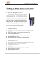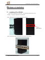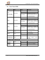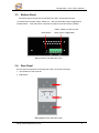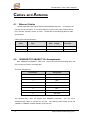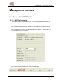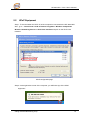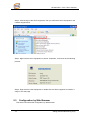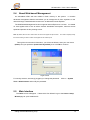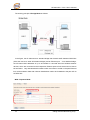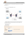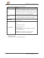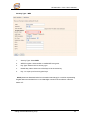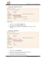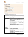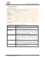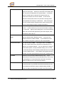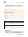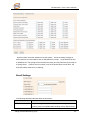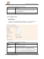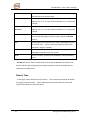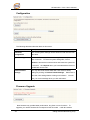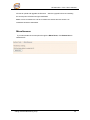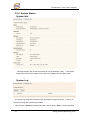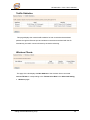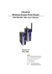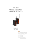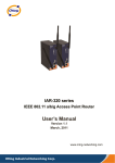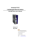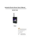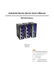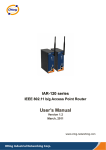
1
Industrial Wireless Access Point IAP-6002-WA / WA+ User’s Manual Version 1.0 May, 2008. ORing Industrial Networking Corp. 4F, NO.3, Lane235, Baociao Rd. Sindian City, Taipei County 23145 Taiwan, R.O.C. Tel: + 886 2 2918 3036 Fax: + 886 2 2918 3084 Website: www.oring-networking.com E-mail: [email protected] Table of Content Getting to Know Your Access Point ............................................................ 1 1.1 About the ORing Access Point ................................................................................. 1 1.2 Software Features .................................................................................................... 1 1.3 Hardware Features................................................................................................... 1 Hardware Installation.................................................................................... 2 2.1 Installation AP on DIN-Rail ....................................................................................... 2 2.2 Wall Mounting Installation ........................................................................................ 3 Hardware Overview....................................................................................... 5 3.1 Front Panel............................................................................................................... 5 3.2 Front Panel LEDs ..................................................................................................... 7 3.3 Bottom Panel............................................................................................................ 8 3.4 Rear Panel ............................................................................................................... 8 Cables and Antenna...................................................................................... 9 4.1 Ethernet Cables........................................................................................................ 9 4.2 100BASE-TX/10BASE-T Pin Assignments .............................................................. 9 4.3 Wireless Antenna ................................................................................................... 10 Management Interface .................................................................................11 5.1 Explore IAP-6002-WA / WA+...................................................................................11 5.1.1 AP-Tool software.................................................................................................11 5.2 UPnP Equipment.................................................................................................... 12 5.3 Configuration by Web Browser .............................................................................. 13 5.4 About Web-based Management ............................................................................ 14 5.5 Main Interface......................................................................................................... 14 5.5.1 Basic Setting ...................................................................................................... 15 Setting Operation Mode.............................................................................................. 15 Setting WDS (Bridge Mode) ....................................................................................... 16 Setting Wireless.......................................................................................................... 20 LAN Setting................................................................................................................. 24 Setting DHCP Server.................................................................................................. 26 5.5.2 Advanced Setting............................................................................................... 27 Wireless ...................................................................................................................... 27 MAC Filter................................................................................................................... 29 System Event.............................................................................................................. 29 Email Settings............................................................................................................. 30 SNMP Settings ........................................................................................................... 31 Syslog Server Settings ............................................................................................... 31 5.5.3 System Tools...................................................................................................... 32 Administrator............................................................................................................... 32 Date & Time ................................................................................................................ 33 Configuration .............................................................................................................. 35 Firmware Upgrade ...................................................................................................... 35 Miscellaneous ............................................................................................................. 36 5.5.4 System Status .................................................................................................... 37 System Info................................................................................................................. 37 System Log................................................................................................................. 37 Traffic Statistics........................................................................................................... 38 Wireless Clients .......................................................................................................... 38 5.5.5 Online Help ........................................................................................................ 39 Technical Specifications .............................................................................40 IAP-6002-WA / WA+ User’s Manual Getting to Know Your Access Point 1.1 About the ORing Access Point IAP-6002-WA / WA+ are reliable IEEE802.11b/g WLAN with 2 ports LAN Access Point. It can be configured to operate in AP/Bridge/Repeater mode. You can configure IAP-6002-WA / WA+ by Window Utility or WEB interfaces via LAN port or WLAN interface. IAP-6002-WA / WA+ provide dual Ethernet ports in switch mode, so you can use Daisy Chain to reduce the usage of Ethernet switch ports. IAP-6002-WA+ also provides PD feature on ETH2 which is fully compliant with IEEE802.3af P.O.E. specification. Therefore, IAP-6002-WA / WA+ are one of the best communication solutions for wireless application. 1.2 Software Features High Speed Air Connectivity: WLAN interface support up to 54Mbps link speed connection Highly Security Capability: WEP/WPA/WPA2/Radius/TKIP supported Support AP/Bridge/Repeater Mode Switch Mode Supported: Daisy Chain support to reduce usage of switch ports Secured Management by HTTPS Event Warning by Syslog, Email, SNMP Trap, Relay and Beeper 1.3 Hardware Features Fully Compliant with IEEE802.3af (Power Device at ETH2, IAP-6002-WA+ only) Redundant Power Inputs: 12~48 VDC on terminal block 10/100Base-T(X) Ethernet port Casing: IP-30 Dimensions(W x D x H) : 52 mm(W)x 106 mm( D )x 144 mm(H) Operating Temperature: -10 to 55oC Storage Temperature: -20 to 85oC Operating Humidity: 5% to 95%, non-condensing 1 ORing Industrial Networking Corp. IAP-6002-WA / WA+ User’s Manual Hardware Installation 2.1 Installation AP on DIN-Rail Each AP has a DIN-Rail kit on rear panel. The DIN-Rail kit helps AP to fix on the DIN-Rail. It is easy to install the AP on the DIN-Rail: Step 1: Slant the AP and mount the metal spring to DIN-Rail. Metal Spring Step 2: Push the AP toward the DIN-Rail until you heard a “click” sound. ORing Industrial Networking Corp. 2 IAP-6002-WA / WA+ User’s Manual 2.2 Wall Mounting Installation Each AP has another installation method to fix the AP. A wall mount panel can be found in the package. The following steps show how to mount the AP on the wall: Step 1: Remove DIN-Rail kit. Step 2: Use 6 screws that can be found in the package to combine the wall mount panel. Just like the picture shows below: 3 ORing Industrial Networking Corp. IAP-6002-WA / WA+ User’s Manual The screws specification shows in the following two pictures. In order to prevent the AP from any damage, the screws should not larger than the size that used in IAP-6002-WA / WA+. Pozidrive Step 3: Mount the combined AP on the wall. ORing Industrial Networking Corp. 4 IAP-6002-WA / WA+ User’s Manual Hardware Overview 3.1 Front Panel The following table describes the labels that stick on the IAP-6002-WA / WA+. Port Description 10/100 RJ-45 fast 2 10/100Base-T(X) RJ-45 fast Ethernet ports support Ethernet ports auto-negotiation. Default Setting : Speed: auto P.O.E. PD Port ETH2 of IAP-6002-WA+ compliant with IEEE802.3af P.O.E. specifications ANT. 5 Reversed SMA connector for external antenna. ORing Industrial Networking Corp. IAP-6002-WA / WA+ User’s Manual IAP-6002-WA IAP-6002-WA+ 1. 2.4GHz antenna with typical 2.0dbi antenna. 2. LED for P.O.E. power and system status. When the P.O.E. power links, the green LED will be light on. 3. LED for PWR1 and system status. When the PWR1 links, the green LED will be light on. 4. LED for PWR2 and system status. When the PWR2 links, the green LED will be light on. 5. LED for Fault Relay. When the fault occurs, the amber LED will be light on. 6. 10/100Base-T(X) Ethernet ports. (IAP-6002-WA+ contains PD function of P.O.E.) 7. LED for Ethernet ports status. 8. LED for WLAN link status. 9. LED for WLAN signal strength. ORing Industrial Networking Corp. 6 IAP-6002-WA / WA+ User’s Manual 3.2 Front Panel LEDs LED P.O.E. Color Status Description Green On P.O.E. power connected. Green blinking Device been located Green/Red (IAP-6002-WA+) Indicates an IP conflict, or Red blinking DHCP or BOOTP server did not respond properly PWR1 Green On DC power 1 activated. Green blinking Device been located Green/Red Indicates an IP conflict, or Red blinking DHCP or BOOTP server did not respond properly PWR2 Green On DC power 2 activated. Green blinking Device been located Green/Red Indicates an IP conflict, or Red blinking DHCP or BOOTP server did not respond properly Fault Amber WLAN Green On Fault relay. Power failure or Port down/fail. On WLAN activated. Blinking WLAN Data transmitted. WLAN signal strength. WLAN Strength Green On 1<25%, 2<50%, 3<75%, 4<100% 10/100Base-T(X) Fast Ethernet ports 10Mbps LNK/ACT 100Mbps LNK/ACT 7 Amber Green On Port link up at 10Mbps. Blinking Data transmitted. On Port link up at 100Mbps. Blinking Data transmitted. ORing Industrial Networking Corp. IAP-6002-WA / WA+ User’s Manual 3.3 Bottom Panel The bottom panel components of IAP-6002-WA / WA+ are showed as below: 1. Terminal block includes: PWR1, PWR2 (12 ~ 48V DC) and Relay output (1A@24VDC). 2. Reset bottom. Push the bottom 3 seconds for reset; 5 seconds for factory default. PWR1, PWR2 (12-48V DC) and Reset Button Relay output (1A@24VDC). Bottom panel of IAP-6002-WA / WA+ 3.4 Rear Panel The rear panel components of IAP-6002-WA / WA+ are showed as below: 1. Screw holes for wall mount kit. 2. DIN-Rail kit Rare panel of IAP-6002-WA / WA+ ORing Industrial Networking Corp. 8 IAP-6002-WA / WA+ User’s Manual Cables and Antenna 4.1 Ethernet Cables The IAP-6002-WA / WA+ WLAN AP have standard Ethernet ports. According to the link type, the AP use CAT 3, 4, 5,5e UTP cables to connect to any other network device (PCs, servers, switches, routers, or hubs). Please refer to the following table for cable specifications. Cable Types and Specifications 4.2 Cable Type 10BASE-T Cat. 3, 4, 5 100BASE-TX Cat. 5 100-ohm UTP 100-ohm Max. Length Connector UTP 100 m (328 ft) RJ-45 UTP 100 m (328 ft) RJ-45 100BASE-TX/10BASE-T Pin Assignments With 100BASE-TX/10BASE-T cable, pins 1 and 2 are used for transmitting data, and pins 3 and 6 are used for receiving data. RJ-45 Pin Assignments Pin Number Assignment 1 TD+ 2 TD- 3 RD+ 4 Not used 5 Not used 6 RD- 7 Not used 8 Not used The IAP-6002-WA / WA+ AP support auto MDI/MDI-X operation. straight-through cable to connect PC and AP. You can use a The following table below shows the 10BASE-T/ 100BASE-TX MDI and MDI-X port pin outs. 9 ORing Industrial Networking Corp. IAP-6002-WA / WA+ User’s Manual MDI/MDI-X pins assignment Pin Number MDI port MDI-X port 1 TD+(transmit) RD+(receive) 2 TD-(transmit) RD-(receive) 3 RD+(receive) TD+(transmit) 4 Not used Not used 5 Not used Not used 6 RD-(receive) TD-(transmit) 7 Not used Not used 8 Not used Not used Note: “+” and “-” signs represent the polarity of the wires that make up each wire pair. 4.3 Wireless Antenna A 2.4GHz antenna is used for IAP-6002-WA / WA+ and connected with a reversed SMA connector. External antenna also can be applied with this connector. ORing Industrial Networking Corp. 10 IAP-6002-WA / WA+ User’s Manual Management Interface 5.1 Explore IAP-6002-WA / WA+ 5.1.1 AP-Tool software Each model contains friendly software, AP-Tool, to explore IAP-6002-WA / WA+ on local area network. Step 1: Open the AP tool and click “Refresh list”, the AP devices will show on the list. Step 2: Choose your access point, and it will show the AP attribute. Simultaneity, you can manual set the AP’s IP address. User interface of AP-Tool Step 3: Click “Access via web” button, it will go to web page. 11 ORing Industrial Networking Corp. IAP-6002-WA / WA+ User’s Manual 5.2 UPnP Equipment Step 1: To check whether the UPnP UI of the computer is connected to the IAP-6002-WA / WA+, go to Control Panel > Add or Remove Programs > Windows Components Wizard > Networking Servers > UPnP User Interface and pitch on the UPnP User Interface. UPnP configuration page Step 2: At the right-below corner of the computer, you will find a sign of the UPnP equipment. ORing Industrial Networking Corp. 12 IAP-6002-WA / WA+ User’s Manual Step 3: Click the sign of the UPnP equipment, then you will find the UPnP equipment in the network neighborhood. Step 4: Right click the UPnP equipment to choose “Properties”, it will show as the following pictures: Step 5: Right click the UPnP equipment or double click the UPnP equipment to transfer; it will go to the web page. 5.3 Configuration by Web Browser This section introduces the configuration by Web browser. 13 ORing Industrial Networking Corp. IAP-6002-WA / WA+ User’s Manual 5.4 About Web-based Management An embedded HTML web site resides in flash memory in the system. It contains advanced management features and allows you to manage the AP from anywhere on the network through a standard web browser such as Microsoft Internet Explorer. The Web-Based Management function supports Internet Explorer 5.0 or later. It is based on Java Applets with an aim to reduce network bandwidth consumption, enhance access speed and present an easy viewing screen. Note: By default, IE5.0 or later version does not allow Java Applets to open sockets. You need to explicitly modify the browser setting in order to enable Java Applets to use network ports. Through the front section’s information, you will see as follows, enter your user name (admin) and your password (leave blank by default), then click OK to continue. Login screen For security reasons, we strongly suggest you change the password. Click on System Tools > Administrator and modify the password. 5.5 Main Interface The Home screen will appear. Please click “Run Wizard” to go to the Home > Setup Wizard page to quick install the AP. ORing Industrial Networking Corp. 14 IAP-6002-WA / WA+ User’s Manual Main interface 5.5.1 Basic Setting Setting Operation Mode Operation mode interface The following table describes the labels in this screen. Label Description Bridge This mode provides Static LAN-to-LAN Bridging functionality. The static LAN-to-LAN bridging function is supported through Wireless Distribution System (WDS). AP This mode provides Access Point services for other wireless clients. AP-Client The AP-Client function provides a 1-to-N MAC address mapping mechanism such that multiple stations behind the AP can transparently connect to the other AP even they didn’t support WDS. 15 ORing Industrial Networking Corp. IAP-6002-WA / WA+ User’s Manual In each mode, the IAP-6002-WA / WA+ forwards packet between its Ethernet interface and wireless interface for wired hosts on the Ethernet side, and wireless hosts on the wireless side. Setting WDS (Bridge Mode) WDS setting interface This type of wireless link is established between two IEEE 802.11 access points. Wireless packets transmitted along the WDS link comply with the IEEE 802.11 WDS (Wireless Distribution System) format at the link layer. Point-to-Multipoint WDS Link ORing Industrial Networking Corp. 16 IAP-6002-WA / WA+ User’s Manual Point-to-Point WDS Link The following table describes the labels in this screen. Label Description WDS Mode This mode provides Static LAN-to-LAN Bridging functionality. The static LAN-to-LAN bridging function is supported through Wireless Distribution System (WDS). Encryption Type Select the type of security for your wireless network WDS Key Fill in the encryption key when Encryption Type is TKIP or AES. Peer MAC Address Set the Mac address(es) of other access point(s). Simultaneity, choose on “Enable”. First of all, if APs link with WDS mode, it should obey the following rules: 1. LAN IP Address should set different IP in the same network. 2. All AP’s DHCP Server should set shutdown. 3. WDS should set Enable. 4. Each AP should have the same setting except ‘Peer Mac Address’ set to the other’s Mac address 5. WEP Key and Channel should be the same, and each AP’s SSID should be broadcast to see in the other’s computer. 6. AP’s distance should limit to a certainty area. 17 ORing Industrial Networking Corp. IAP-6002-WA / WA+ User’s Manual WDS – Restricted Mode The peer WDS APs are according to the MAC address listed in "Peer Mac Address" fields. WDS –Bridge Mode Same as Restrict mode in functionality and also one WDS link side can not set Peer Mac Address 1-4. ORing Industrial Networking Corp. 18 IAP-6002-WA / WA+ User’s Manual The working principle of Bridge Mode as follows: In the figure, the AP behaves as a standard bridge that forwards traffic between WDS links (links that connect to other AP/wireless bridges) and an Ethernet port. As a standard bridge, the AP learns MAC addresses of up to 64 wireless or 128 total wired and wireless network devices, which are connected to their respective Ethernet ports to limit the amount of data to be forwarded. Only data destined for stations which are known to reside on the peer Ethernet link, multicast data or data with unknown destinations need to be forwarded to the peer AP via the WDS link. WDS –Repeater Mode 19 ORing Industrial Networking Corp. IAP-6002-WA / WA+ User’s Manual Same as Restrict mode in functionality and also one WDS link side can not set Peer Mac Address 1-4. The working principle of Repeater Mode as follows: In the figure, Repeater is used to extend the range of the wireless infrastructure by forwarding traffic between associated wireless stations and another repeater or AP connected to the wired LAN. Setting Wireless ORing Industrial Networking Corp. 20 IAP-6002-WA / WA+ User’s Manual The following table describes the labels in this screen. Label Description Service Set Identifier Default is the default setting. a unique name that identifies a network. SSID The SSID is All devices on the network must share the same SSID name in order to communicate on the network. If you change the SSID from the default setting, input your new SSID name in this field. Channel 6 is the default channel, input a new number if you want Channel to change the default setting. All devices on the network must be set to the same channel to communicate on the network. Peer AP SSID Only Operation Mode selects AP-Client Mode, you should enter the peer AP SSID. Select the type of security for your wireless network at Security Type: None: Select for no security. WEP: Select for security. Security options WPA-PSK/WPA2-PSK: Select for WPA-PSK or WPA2-PSK without a RADIUS server. WPA/WPA2: Select for WPA (Wi-Fi Protected Access) authentication in conjunction with a RADIUS server. Security Type – None No security protection on your wireless LAN access. 21 ORing Industrial Networking Corp. IAP-6002-WA / WA+ User’s Manual Security Type – WEP 1. Security Type: Select WEP 2. WEP Encryption: Select 64 Bit or 128 Bit WEP encryption. 3. Key Type: Select ASCII or Hex key type. 4. Default Key Index: Select one of the keys to be the active key. 5. Key 1-4: Input up to four encryption keys. ASCII (American Standard Code for Information Interchange) is a code for representing English letters as numbers from 0-127. Hex digits consist of the numbers 0-9 and the letters A-F. ORing Industrial Networking Corp. 22 IAP-6002-WA / WA+ User’s Manual Security Type – WPA-PSK/WPA2-PSK 1. Security Type: Select WPA-PSK/WPA2-PSK. 2. Encryption Type: Select TKIP or AES encryption. 3. Share Key: Enter your password. The password can be between 8 and 64 characters. Security Type – WPA /WPA2 1. Security Type: Select WPA/WPA2 2. Radius Server IP: Enter the IP address of the RADIUS Server. 3. Port: Enter the RADIUS port (1812 is default). 4. Shared Secret: Enter the RADIUS password or key. 23 ORing Industrial Networking Corp. IAP-6002-WA / WA+ User’s Manual RADIUS (Remote Authentication Dial-in User Service) is the industrial standard agreement, and it is used to provide an identify verification. The Radius customer (is usually a dial-in server, VPN server or wireless point) send your proof and the conjunction parameter to the Radius server by Radius news. The Radius server validates the request of the Radius customer, and return Radius news to back. Radius server validates your proof, also carry on the authorization. So the Radius server received by ISA server responded (point out the customer carries proof to be not granted) and it means that the Radius server did not authorize you to carry. Even if the proof has already passed an identify verification, the ISA server may also refuse you to carry a claim according to the authorization strategy of the Radius server. The principle of the Radius server shows in the following pictures: LAN Setting The Basic Setting > LAN Setting page is mainly set IP address for LAN interface. To access the AP normally, a valid IP address of your LAN should be specified to the LAN interface. The default IP setting is DHCP server (Obtain an IP address automatically). ORing Industrial Networking Corp. 24 IAP-6002-WA / WA+ User’s Manual The following table describes the labels in this screen. Label Description Obtain an IP address Select this option if you would like to have an IP address automatically automatically assigned to the IAP-6002-WA / WA+ by DHCP server in your network Use the following IP address Select this option if you are manually assigning an IP address. IP Address: There is a default IP address in the AP, and you can input a new IP address. Subnet Mask: 255.255.255.0 is the default Subnet Mask. All devices on the network must have the same subnet mask to communicate on the network. Default Gateway: Enter the IP address of the router in your network. Obtain DNS server This option is selected by DHCP server. address automatically Use the following DNS server addresses This option is selected by manually set Preferred DNS: There is a default DNS server, and you can input another new DNS server. Alternate DNS: There is a default DNS server, and you can input another new DNS server. 25 ORing Industrial Networking Corp. IAP-6002-WA / WA+ User’s Manual Setting DHCP Server The following table describes the labels in this screen. Label Description DHCP Server Enable or Disable the DHCP Server function. Enable – the AP will be the DHCP server on your local network Start IP Address The dynamic IP assign range. Low IP address is the beginning of the dynamic IP assigns range. assign range is from For example: dynamic IP 192.168.1.100 to 192.168.1.200. 192.168.1.100 will be the Start IP address. Maximum Number of The dynamic IP assign range. High IP address is the end of the IPs dynamic IP assigns range. For example: dynamic IP assign range is from 192.168.1.100 to 192.168.1.200. 100 will be enter into textbox. Lease Time (Hour) It is the time period that system will reset the dynamic IP assignment to ensure the dynamic IP will not been occupied for a long time or the server doesn’t know that the dynamic IP is idle. DHCP Clients List List the devices on your network that are receiving dynamic IP addresses from the IAP-6002-WA / WA+. ORing Industrial Networking Corp. 26 IAP-6002-WA / WA+ User’s Manual 5.5.2 Advanced Setting Wireless The following table describes the labels in this screen. Label Description Beacon Interval The default value is 100. The Beacon Interval value indicates the frequency interval of the beacon. A beacon is a packet broadcast by the AP to synchronize the wireless network. 50 is recommended in poor reception. DTIM Interval The default value is 1. This value, between 1 and 255 milliseconds, indicates the interval of the Delivery Traffic Indication Message (DTIM). A DTIM field is a countdown field informing clients of the next window for listening to broadcast and multicast messages. When the AP has buffered broadcast or multicast messages for associated clients, it sends the next DTIM with a DTIM Interval value. Its clients hear the beacons and awaken to receive the broadcast and multicast messages. Fragmentation This value should remain at its default setting of 2346. The Threshold range is 256-2346 bytes. It specifies the maximum size for a packet before data is fragmented into multiple packets. If you experience a high packet error rate, you may slightly increase the Fragmentation Threshold. Setting the Fragmentation Threshold too low may result in poor network performance. Only minor modifications of this value are recommended. 27 ORing Industrial Networking Corp. IAP-6002-WA / WA+ User’s Manual RTS Threshold This value should remain at its default setting of 2347. The range is 0-2347 bytes. Should you encounter inconsistent data flow, only minor modifications are recommended. If a network packet is smaller than the preset RTS threshold size, the RTS/CTS mechanism will not be enabled. The AP sends Request to Send (RTS) frames to a particular receiving station and negotiates the sending of a data frame. After receiving an RTS, the wireless station responds with a Clear to Send (CTS) frame to acknowledge the right to begin transmission. Xmit Power This value ranges from 1 - 100 percent, default value is 100 percent. A safe increase of up to 60 percent would be suitable for most users. Higher power settings are not recommended for users due to excess heat generated by the radio chipset, which can affect the life of the AP. Wireless Network If you have Wireless-G and 802.11b devices in your network, then Mode keep the default setting, BG Mixed mode. If you have only Wireless-G devices, select G Mode. If you would like to limit your network to only 802.11b devices, then select B Mode. Transmission Rate The default setting is Auto. The range is from 1 to 54Mbps. The rate of data transmission should be set depending on the speed of your wireless network. You can select from a range of transmission speeds, or keep the default setting, Auto, to have the AP automatically use the fastest possible data rate and enable the Auto-Fallback feature. Auto-Fallback will negotiate the best possible connection speed between the AP and a wireless client. Preamble Values are Long and Short, default value is Long. If your wireless device supports the short preamble and you are having trouble getting it to communicate with other 802.11b devices, make sure that it is set to use the long preamble SSID Broadcast When wireless clients survey the local area for wireless networks to associate with, they will detect the SSID broadcast by the AP. To broadcast the AP SSID, keep the default setting, Enable. If you do not want to broadcast the AP SSID, then select Disable. ORing Industrial Networking Corp. 28 IAP-6002-WA / WA+ User’s Manual MAC Filter Use Advanced Setting > MAC Filters to allow or deny wireless clients, by their MAC addresses, from accessing the IAP-6002-WA / WA+. You can manually add a MAC address or select the MAC address from Connected Clients that are currently connected to the AP. The following table describes the labels in this screen. Label Description MAC Filter Enable or disable the function of MAC filter. MAC address allowed or denied option is selected by you. MAC Filter List This list will display the MAC addresses that are in the selected filter. Connected Clients This list will display the wireless MAC addresses that linked with AP. MAC Address MAC addresses need to be added to or clear from MAC filter list. Apply Click Apply to set the configurations. System Event When the AP event triggered, the notification procedure will be performed according to the type of the event. Which notification would be performed depends on the selection of corresponding option in the Advanced Setting > System Event page. 29 ORing Industrial Networking Corp. IAP-6002-WA / WA+ User’s Manual System events record the activities of the AP system. When the setting changes or action performs, the event will be sent to administrator by email. A trap will also be sent to SNMP server. The Syslog will record the event locally and may send the log remotely to a Syslog server. If serious event occurred, such as the power failure or link down, the fault LED will be switched on as warning. Email Settings The following table describes the labels in this screen. Label Description SMTP Server Simple Message Transfer Protocol, enter the backup host to use if primary host is unavailable while sending mail by SMTP server. ORing Industrial Networking Corp. 30 IAP-6002-WA / WA+ User’s Manual Server Port Specify the port where MTA can be contacted via SMTP server. E-mail Address 1-4 Inputs specify the destination mail address. SNMP Settings The following table describes the labels in this screen. Label Description SNMP Agent SNMP (Simple Network Management Protocol) Agent is a service program that runs on the access point. The agent provides management information to the NMS by keeping track of various operational aspects of the AP system. Turn on to open this service and off to shutdown it. SNMP Trap Server Specify the IP of trap server, which is the address to which it will 1-4 send traps AP generates. Community Community is essentially password to establish trust between managers and agents. Normally "public" is used for read-write community. SysLocation Specify sysLocation string. SysContact Specify sysContact string. Syslog Server Settings 31 ORing Industrial Networking Corp. IAP-6002-WA / WA+ User’s Manual The following table describes the labels in this screen. Label Description Syslog Server IP Not only the syslog keeps the logs locally, it can also log to remote server. Specify the IP of remote server. Leave it blank to disable logging remotely. Syslog Server Port Specify the port of remote logging. Default port is 514. 5.5.3 System Tools Administrator In this page, you can change the username and password. The new password must be typed twice to confirm (the default Name and Password is “admin” and “”). The following table describes the labels in this screen. Label Description Old Name This field displays the old login name. It's read only. The default value of login name is "admin". Old Password Before making a new setting, you should provide the old password for a verify check. Acceptable inputs of this field contains '0-9', 'a-z', 'A-Z' and must be between 0 to 15 characters in length. The factory default value of login password is null. New Name Enter a new login name. Acceptable inputs of this field contains ORing Industrial Networking Corp. 32 IAP-6002-WA / WA+ User’s Manual '0-9', 'a-z', 'A-Z' and must be between 1 to 15 characters in length. This field can not accept null input. New Password Enter a new login password. Acceptable inputs of this field contains '0-9', 'a-z', 'A-Z' and must be between 0 to 15 characters in length. Confirm New Retype the password to confirm it. Acceptable inputs of this field Password contains '0-9', 'a-z', 'A-Z' and must be between 0 to 15 characters in length. Web Protocol Choose on the protocol for web. The default value is HTTP, if you want the web pages’ security is better, choose the HTTPS protocol. Port Corresponding to the Web protocol, there is a default port (HTTP: 80, HTTPS: 443). And you can enter another number which should be in range of 1-65535. Web Access Control Choose the checkbox of the Wired and Wireless; you can visit the web page through the mode you choose. UPnP Pitch on “Enable”, and the UPnP will display in the right-behind corner. HTTPS (HTTP over SSL) is a Web protocol developed by Netscape and built into its browser that encrypts and decrypts user page requests as well as the pages that are returned by the Web server. Date & Time In this page, set the date & time of the device. The correct date & time will be helpful for logging of system events. A NTP (Network Time Protocol) client can be used to synchronize date & time with NTP server. 33 ORing Industrial Networking Corp. IAP-6002-WA / WA+ User’s Manual The following table describes the labels in this screen. Label Description Local Date Set local date manually. Local Time Set local time manually. Time Zone Select the time zone manually Get Current Date & Click this button, you can set the time from browser. Time from Browser NTP Enable or disable NTP function to get the time from the NTP server. NTP Server 1 The initial choice about NTP Server. NTP Server 2 The second choice about NTP Server. Synchronize Set the time, and the AP’s time synchronize with the NTP Server at the time ORing Industrial Networking Corp. 34 IAP-6002-WA / WA+ User’s Manual Configuration The following table describes the labels in this screen. Label Description Download The current system settings can be saved as a file onto the local configuration hard drive. Upload configuration The saved file or any other saved setting file can be uploaded back on the AP. To reload a system settings file, click on Browse to browse the local hard drive and locate the system file to be used. Click Upload when you have selected the file to be loaded back onto the AP. Restore Default You may also reset the IAP-6002-WA / WA+ back to factory Settings settings by clicking on Restore Default Settings. Make sure to save the unit’s settings before clicking on this button. You will lose your current settings when you click this button. Firmware Upgrade New firmware may provide better performance, bug fixes or more functions. To upgrade, you need a firmware file correspond to this AP model. It will take several 35 ORing Industrial Networking Corp. IAP-6002-WA / WA+ User’s Manual minutes to upload and upgrade the firmware. After the upgrade is done successfully, the access point will reboot and get revalidated. Notice: DO NOT POWER OFF THE AP OR PRESS THE RESET BUTTON WHILE THE FIRMWARE IS BEING UPGRADED. Miscellaneous If you want restart the access point through the Warm Reset, click Restart Now to restart the AP. ORing Industrial Networking Corp. 36 IAP-6002-WA / WA+ User’s Manual 5.5.4 System Status System Info This page displays the current information for the IAP-6002-WA / WA+. It will display model name, as well as firmware version, Ethernet, Wireless info and device time. System Log The system log tracks the important events and setting changes of the AP. If the AP is rebooted, the logs are automatically cleared. Click the button 'Refresh' to refresh the page; Click the button 'Clear' to clear log entries. 37 ORing Industrial Networking Corp. IAP-6002-WA / WA+ User’s Manual Traffic Statistics This page displays the network traffic statistics for both received and transmitted packets through the Ethernet port and wireless connections associated with the AP. Simultaneity, the traffic counter will reset by the device rebooting. Wireless Clients This page of the list displays the Mac Address of the wireless clients connected. Current TX Rate is corresponding to the Transmission Rate in the Advanced Setting > Wireless pages. ORing Industrial Networking Corp. 38 IAP-6002-WA / WA+ User’s Manual 5.5.5 Online Help Click on any item in the Online Help screen for more information. 39 ORing Industrial Networking Corp. IAP-6002-WA / WA+ User’s Manual Technical Specifications LAN Interface RJ45 Ports 2 x 10/100Base-T(X), Auto MDI/MDI-X P.O.E. PD (Power Device) Present at ETH2 of IAP-6002-WA+ ETH2 act as Power Device (IEEE802.3af): IEEE 802.3af compliant input interface Power consumption: 8Watts max. Over load & short circuit protection Isolation Voltage: 1000 VDC min. Isolation Resistance: 108 ohms min Protocols ICMP, IP, TCP, UDP, DHCP, BOOTP, ARP/RARP, DNS, SNMP MIB II, HTTPS, SNMPV1/V2, Trap, Private MIB WLAN Interface Operating Mode AP/Bridge/Repeater Antenna Connector Reverse SMA Radio Frequency Type DSSS Modulation IEEE802.11a: OFDM with BPSK, QPSK, 16QAM, 64QAM OFDM @ 54 Mbps, CCK @ 11/5.5 Mbps, DQPSK @ 2 Mbps, DBSK @ 1 Mbps EEE802.11b: CCK, DQPSK, DBPSK IEEE802.11g: OFDM with BPSK, QPSK, 16QAM, 64QAM Frequency Band America / FCC: 2.412~2.462 GHz (11 channels) 5.15 to 5.25 GHz (4 channels) Europe CE / ETSI: 2.412~2.472 Ghz (13 channels) 5.15 to 5.25 GHz (4 channels) Transmission Rate IEEE802.11b: 1 / 2 / 5.5 / 11 Mbps IEEE802.11a/g: 6 / 9 / 12 / 18 / 24 / 36 / 48 / 54 Mbps Transmit Power IEEE802.11a/b/g: 18dBm Receiver Sensitivity -81dBm@11Mbps, PER< 8%; -64dBm@54Mbps, PER< 10% Encryption Security ORing Industrial Networking Corp. WEP: (64-bit, 128-bit key supported) 40 IAP-6002-WA / WA+ User’s Manual WPA: WPA2:802.11i (WEP and AES encryption) PSK (256-bit key pre-shared key supported) TKIP encryption Wireless Security SSID broadcast disable LED Indicators PWR 1(2) (P.O.E., IAP-6002-WA+) / Ready: 1) Red On: Power is on and booting up. 2) Green On: Power is on and functioning normally. ETH1 (2) Link / ACT: Orange ON/Blinking: 10 Mbps Ethernet Green ON/Blinking: 100 Mbps Ethernet WLAN Link/ACT: Green WLAN Strength:1<25%, 2<50%, 3<75%, 4<100% Fault: Power or LAN link down (Red) Power Requirements Power Input Voltage Dual power inputs PWR1/2: 12 ~ 48VDC in 6-pin Terminal Block Reverse Polarity Protection Present Power Consumption 6 Watts Environmental Operating Temperature -10 to 55oC Storage Temperature -20 to 85oC Operating Humidity 5% to 95%, non-condensing Mechanical Dimensions(W x D x H) 52 mm(W)x 106 mm(D)x 144 mm(H) Casing IP-30 protection Regulatory Approvals Regulatory Approvals FCC Part 15, CISPER (EN55022) class A EMS EN61000-4-2 (ESD), EN61000-4-3 (RS), EN61000-4-4 (EFT), EN61000-4-5 (Surge), EN61000-4-6 (CS) Shock IEC 60068-2-27 Free Fall IEC 60068-2-32 Vibration IEC 60068-2-6 Warranty 3 years 41 ORing Industrial Networking Corp.