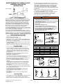
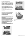
1
Forged Wire Rope Clips
G-450
The Market Leader: Yesterday, Today and Tomorrow
G-429
“Crosby: There is No Equal”
FORGED FOR CRITICAL APPLICATIONS
The proper performance of forged clips depends on
proper manufacturing practices that include good
forging techniques and accurate machining. Forged
clips provide a greater rope bearing surface and more
consistent strength than malleable cast iron clips. Fist
Grip clips provide a saddle for both the “live” and
the “dead” end. Fewer forged clips are required for
each termination than with malleable cast iron clips.
Forged clips reduce the possibility of hidden defects
that are sometimes present in malleable cast iron
clips. Malleable cast iron clips should only be used
in non-critical applications. ANSI, OSHA, and ASTM
recommend only forged clips for critical applications.
COMPETITION
CROSBY
Crosby provides forged
“Red” U-Bolt® Clips and forged
Fist Grip clips which meet or
exceed Federal Specification
Number FF-C-450 and are
considered the industry standard.
Ask: Is the clip forged?
Ask: Is an adequate cradle provided
in the clip base for the wire rope?
Malleable cast iron clips are
sometimes improperly used as
replacements for forged clips.
Only Crosby provides forged
“Red” U-Bolt® Clips from 1/8” to
3-1/2”* and forged Fist Grip clips
from 3/16” through 1-1/2”.
FULL LINE
The proper application of forged clips requires that the
correct type, size, number, and installation instructions
be used (See APPLICATION INFORMATION below
for more information). Availability of a full range of
sizes of forged U-bolt clips and forged Fist Grip clips
are essential for design flexibility.
Ask: Do they have both Fist Grip
and U-bolt clips available?
IDENTIFICATION
The clip’s size, manufacturer’s logo, and a
traceability code should be clearly embossed in the
forging of the clip. These three elements are essential
in developing total confidence in the product.
Ask: Is the manufacturer’s name and
size of clip clearly marked?
Ask: Do they have a full range of
forged wire rope clip sizes?
Ask: Do they have a traceability
system that is actively used in the
manufacturing process?
Most do not have a traceability
system.
APPLICATION INFORMATION
Detailed application information will assist you
in the proper installation of wire rope clips. This
information is most effective when provided at
the point of application, as well as in supporting
brochures and engineering information. The
manufacturer must provide this specific information.
Generic information will not provide all the needed
application instructions. A formal application and
warning system that attracts the attention of the
user, clearly informs the user of the factors involved
in the task, and informs the user with the proper
application procedures as needed.
* The 3-1/2” base is a steel casting.
No competitor has the full line of
forged U-Bolt clips and Fist Grip
clips that Crosby has.
Ask: Does each clip have
the application and warning
information?
Most competitors do not have
application and warnings
information with each clip.
Crosby clearly embosses its
logo, the size, and the Product
Identification Code (PIC) into all
Crosby
“Red” U-bolt® Clip bases and Fist
Grip clips. Crosby’s traceability
system is actively
used throughout the
manufacturing of forged clips.
The material analysis for each heat
of steel, is verified within our own
laboratory.
Crosby provides detailed
application and warning
information for all forged clips.
Each clip is individually bagged
or tagged with the application and
warning information. Testing and
evaluation of special applications
can be performed upon special
request.
Remember, “When buying Crosby, you’re buying more than product, you’re buying Quality.”
32
Copyright © 2013 The Crosby Group LLC
All Rights Reserved
Wire Rope
End Fittings
Crosby Value Added
• Full Line: Crosby provides both forged “Red” U-Bolt® Clips and forged Fist Grip Clips.
• Forged: Crosby “Red” U-Bolt® Clips have forged bases on all sizes, except 3-1/2” (the 3-1/2” base is a steel casting). The
entire clip is galvanized to resist corrosive and rusting action. Clip sizes 1/8” through 1-1/2” have U-Bolts with rolled
threads which enhance the strength of the material and fatigue properties.
• Forged: Fist Grip Clips are forged, and the entire clip is galvanized. The double saddle design eliminates the possibility
of incorrect installation. Designed as an integral part of the clip, the bolts are opposite one another (see G-429 example
below). As result, the nuts can be installed in such a way as to enable the operator to swing the wrench in a full arc for
ease of installation.
• Application Information: Application and warning information is available for both Crosby “Red” U-Bolt® Clips and
Fist Grip Clips. The Crosby Warning System is designed to attract the attention of the user, clearly inform the user of
the factors involved in the task, and provide the user with proper application procedures. Each Crosby “Red” U-Bolt®
Clip and Fist Grip Clip is either bagged or tagged with appropriate application and warning information, thus ensuring
that the information is available at the point of application for each and every clip during installation.
• Material Analysis: Crosby can provide certified material (mill) analysis for each production lot, traceable by the Product
Identification Code (PIC). Crosby, through its own laboratory, verifies the analysis of each heat of steel.
• Testing: Crosby periodically audits the termination efficiencies of the “Red” U-Bolt Clips and Fist Grip Clips. Upon
special request, Crosby will determine the efficiencies of clip assemblies when applied to special rope constructions and
special applications.
G-450
Red-U-Bolt®, Clip
Copyright © 2013 The Crosby Group LLC
All Rights Reserved
G-429
Fist Grip Clip
33
Forged Wire Rope Clips
SEE APPLICATION AND
WARNING INFORMATION
Para Español: www.thecrosbygroup.com
G-450
On Page 56
• Each base has a Product Identification Code (PIC) for material traceability, the name CROSBY or CG,
and a size forged into it.
• Based on the catalog breaking strength of wire rope, Crosby wire rope clips have an efficiency rating
of 80% for 1/8” - 7/8” sizes, and 90% for sizes 1” through 3-1/2”.
• Entire Clip-Galvanized to resist corrosive and rusting action.
• Sizes 1/8” through 2-1/2” and 3” have forged bases.
• All Clips are individually bagged or tagged with proper application instructions and
warning information.
• Clip sizes up through 1-1/2” have rolled threads.
• Meets or exceeds all requirements of ASME B30.26 including identification, ductility, design factor,
proof load and temperature requirements. Importantly, these wire rope clips meet other critical
performance requirements including fatigue life, impact properties and material traceability, not
addressed by ASME B30.26.
• Look for the Red-U-Bolt®, your assurance of Genuine Crosby Clips.
Crosby Clips, all sizes 1/4” and larger, meet the performance requirements of Federal Specification FF-C-450 TYPE 1 CLASS 1, except for those provisions
required of the contractor. For additional information, see page 444.
G-450 Crosby® Clips
Std.
Weight
Rope Size
G-450
Package Per 100
Stock No.
Qty.
(lbs.)
(in.)
(mm)
A
B
C
1/8
3-4*
1010015
100
6
.22
.72
.44
3/16*
5*
1010033
100
10
.25
.97
.56
1/4
6-7
1010051
100
19
.31
1.03
.50
5/16
8
1010079
100
28
.38
1.38
.75
3/8
9-10
1010097
100
48
.44
1.50
.75
7/16
11
1010113
50
78
.50
1.88
1.00
1/2
12-13
1010131
50
80
.50
1.88
1.00
9/16
14-15
1010159
50
109
.56
2.25
1.25
5/8
16
1010177
50
110
.56
2.25
1.25
3/4
18-20
1010195
25
142
.62
2.75
1.44
7/8
22
1010211
25
212
.75
3.12
1.62
1
24-26
1010239
10
252
.75
3.50
1.81
1-1/8
28-30
1010257
10
283
.75
3.88
2.00
1-1/4
32-34
1010275
10
438
.88
4.44
2.22
1-3/8
36
1010293
10
442
.88
4.44
2.22
1-1/2
38
1010319
10
544
.88
4.94
2.38
1-5/8
41-42
1010337
Bulk
704
1.00
5.31
2.62
1-3/4
44-46
1010355
Bulk
934
1.13
5.75
2.75
2
48-52
1010373
Bulk
1300
1.25
6.44
3.00
2-1/4
56-58
1010391
Bulk
1600
1.25
7.13
3.19
2-1/2
62-65
1010417
Bulk
1900
1.25
7.69
3.44
** 2-3/4 ** 68-72 1010435
Bulk
2300
1.25
8.31
3.56
3
75-78
1010453
Bulk
3100
1.50
9.19
3.88
** 3-1/2 ** 85-90 1010426
Bulk
4000
1.50
10.75
4.50
* Electro-plated U-Bolt and Nuts. ** 2-3/4” and 3-1/2” base is made of cast steel.
SS-450
F
.38
.44
.56
.69
.75
.88
.88
.94
.94
1.06
1.25
1.25
1.25
1.44
1.44
1.44
1.63
1.81
2.00
2.00
2.00
2.00
2.38
2.38
G
.81
.94
1.19
1.31
1.63
1.91
1.91
2.06
2.06
2.25
2.44
2.63
2.81
3.13
3.13
3.41
3.63
3.81
4.44
4.56
4.69
5.00
5.31
6.19
H
.99
1.18
1.43
1.66
1.94
2.28
2.28
2.50
2.50
2.84
3.16
3.47
3.59
4.13
4.19
4.44
4.75
5.24
5.88
6.38
6.63
6.88
7.61
8.38
• Each base has a Product Identification Code (PIC) for material traceability, the name CROSBY or “CG”,
and a size forged into it.
• Entire clip is made from 316 Stainless Steel to resist corrosive and rusting action.
• All components are Electro-Polished.
• All Clips are individually bagged or tagged with proper application instructions and warning information.
SS-450 Stainless Steel Wire Rope Clips
Rope Size
(in.)
(mm)
1/8
3-4
3/16
5
1/4
6-7
3/8
9-10
1/2
12-13
5/8
16
34
Dimensions
(in.)
D
E
.47
.37
.59
.50
.75
.66
.88
.73
1.00
.91
1.19
1.13
1.19
1.13
1.31
1.34
1.31
1.34
1.50
1.39
1.75
1.58
1.88
1.77
2.00
1.91
2.34
2.17
2.34
2.31
2.59
2.44
2.75
2.66
3.06
2.92
3.38
3.03
3.88
3.19
4.13
3.69
4.38
4.88
4.75
4.44
5.50
6.00
Std.
Weight
SS-450
Package Per 100
Stock No.
Qty.
(lbs.)
1011250
Bulk
6
1011261
Bulk
10
1011272
Bulk
20
1011283
Bulk
47
1011305
Bulk
77
1011327
Bulk
106
A
.22
.25
.31
.44
.50
.56
B
.72
.97
1.03
1.50
1.88
2.38
C
.44
.56
.50
.75
1.00
1.25
Dimensions
(in.)
D
E
.47
.41
.59
.50
.75
.66
1.00
.91
1.19
1.13
1.31
1.34
F
.38
.44
.56
.75
.88
.94
G
.81
.94
1.19
1.63
1.91
2.06
H
.94
1.16
1.44
1.94
2.28
2.50
Copyright © 2013 The Crosby Group LLC
All Rights Reserved
SEE APPLICATION AND
WARNING INFORMATION
Para Español: www.thecrosbygroup.com
NEW STYLE
FIST GRIP®
CLIPS
3/16” - 5/8”
Fist Grip® wire clips meet
or exceed the performance
requirements of Federal
Specification FF-C-450 Type
III, Class 1, except for those
provisions required of the
contractor. For additional
information, see page 444.
3/16” - 5/8”
• Entire clip is Galvanized to resist corrosive and rusting action.
• Based on the catalog breaking strength of wire rope, Crosby wire rope
clips have an efficiency rating of 80% for 3/16” - 7/8” sizes, and 90% for
sizes 1” through 1-1/2”.
• Bolts are an integral part of the saddle. Nuts can be installed in such a
way as to enable the operator to swing the wrench in a full arc for
fast installation.
• All sizes have forged steel saddles.
• All Clips are individually bagged or tagged with proper application
instructions and warning information.
• Meets or exceeds all requirements of ASME B30.26 including identification, ductility, design factor, proof load and temperature requirements.
Importantly, these wire rope clips meet other critical performance
requirements including fatigue life, impact properties and material
traceability, not addressed by ASME B30.26.
• Assembled with standard heavy hex nuts.
On Page 57
FIST GRIP®
CLIPS
3/4” - 1-1/2”
G-429 Fist Grip® Clips
Std.
Rope Size
G-429
Package
(in.)*
(mm)
Stock No.
Qty.
3/16 - 1/4
5-7
1010471
100
5/16
8
1010499
100
3/8
10
1010514
50
7/16 - 1/2
11-13
1010532
50
9/16 - 5/8
14-16
1010550
50
3/4
18-20
1010578
25
7/8
22
1010596
25
1
24-26
1010612
10
1-1/8
28-30
1010630
10
1-1/4
32-34
1010658
10
1-3/8 - 1-1/2
36-40
1010676
Bulk
* Sizes through 5/8” incorporate New Style Design.
Weight
Per 100
(lbs.)
23
28
40
62
103
175
225
300
400
400
700
C
.40
.47
.51
.59
.72
.86
.97
1.13
1.28
1.34
1.56
D
.94
1.06
1.06
1.25
1.50
1.81
2.12
2.25
2.38
2.50
3.00
Dimensions
(in.)
E
.38
.38
.44
.50
.63
.75
.75
.75
.88
.88
1.00
G
1.41
1.50
1.84
2.21
2.72
2.94
3.31
3.72
4.22
4.25
5.56
N
1.44
1.54
1.78
2.15
2.57
2.67
2.86
3.06
3.44
3.56
4.12
3/4” - 1-1/2”
Copyright © 2013 The Crosby Group LLC
All Rights Reserved
35
Wire Rope
End Fittings
Fist Grip® Wire Rope Clips
S-421T Wedge Sockets
Scan this QR code
with your smart
device to view our
Terminator video.
S-421T
Wedge sockets meet the
performance requirements of
Federal Specification
RR-S-550E, Type C, except
those provisions required of
the contractor. For additional
information, see page 444.
SEE APPLICATION AND
WARNING INFORMATION
Para Español: www.thecrosbygroup.com
On Page 58
• Wedge socket terminations have an efficiency rating of 80% based on the catalog strength of XXIP
wire rope.
• Meets or exceeds all requirements of ASME B30.26 including identification, ductility, design
factor, proof load and temperature requirements. Importantly, these sockets meet other critical
performance requirements including fatigue life, impact properties and material traceability, not
addressed by ASME B30.26.
• Type Approval and certification in accordance with ABS 2007 Steel Vessel Rules.1-1-17.7, and ABS
Guide for Certification of Cranes.
• Basket is cast steel and individually magnetic particle inspected.
• Pin diameter and jaw opening allows wedge and socket to be used in conjunction with closed
swage and spelter sockets.
• Secures the tail or “dead end” of the wire rope to the wedge, thus eliminates loss or “Punch out”
of the wedge.
• Eliminates the need for an extra piece of rope, and is easily installed.
• The TERMINATOR™ wedge eliminates the potential breaking off of the tail due to fatigue.
• The tail, which is secured by the base of the clip and the wedge, is left undeformed and available
for reuse.
• Incorporates Crosby’s patented QUIC-CHECK® “Go” and “No-Go” feature cast into the wedge.
The proper size rope is determined when the following criteria are met:
1) The wire rope should pass thru the “Go” hole in the wedge.
2) The wire rope should NOT pass thru the “No-Go” hole in the wedge.
• Utilizes standard Crosby Red-U-Bolt® wire rope clip.
• The 3/8” thru 1-1/8” standard S-421 wedge socket can be retrofitted with the new style
TERMINATOR™ wedge.
• Available with Bolt, Nut, and Cotter Pin.
• U.S. patent 5,553,360, Canada patent 2,217,004 and foreign equivalents.
• Meets the performance requirements of EN 13411-6: 2003.
S-421T Wedge Sockets
Assembly includes Socket, Wedge, Pin and Wire Rope Clip
Wire Rope
Dia.
(in.)
3/8
1/2
5/8
3/4
7/8
1
1-1/8
1-1/4
(mm)
9-10
11-13
14-16
18-19
20-22
24-26
28
30-32
S-421T
Stock
No.
1035000
1035009
1035018
1035027
1035036
1035045
1035054
1035063
API 2C
S-421T
Stock
No.
1035005
1035014
1035023
1035032
1035041
1035050
1035059
1035068
Weight
Each
(lbs.)
3.18
6.15
9.70
14.50
21.50
30.75
45.30
64.90
S-421TW
Stock No.
Wedge Only
1035555
1035564
1035573
1035582
1035591
1035600
1035609
1035618
API 2C
S-421TW
Stock No.
Wedge Only
1092230
1092248
1092257
1092293
1092319
1092337
1092364
1092375
Wedge Only
Weight
Each
(lbs.)
.50
1.05
1.79
2.60
4.00
5.37
7.30
10.60
Optional G-4082
Bolt, Nut & Cotter
G-4082
Weight
Stock
Each
No.
(lbs.)
1092227
.38
1092236
.69
1092254
1.15
1092281
1.91
1092307
3.23
1092325
5.40
1092343
7.50
1092372
10.34
Wire Rope
Dia.
Dimensions
API 2C
(in.)
S-421T
C
S-421T
Stock
(in.) (mm)
+/Stock No.
No.
A
B
.09
D
G
H
J*
K*
L
P
R
S
T
U
V
3/8
9-10
1035000
1035005 5.69
2.72
.81
.81
1.38
3.06
7.80
1.88
.88
1.56
.44
2.13
.44
1.25
1.38
1/2
11-13
1035009
1035014
6.88
3.47
1.00
1.00
1.62
3.76
8.91
1.26
1.06
1.94
.50
2.56
.53
1.75
1.88
5/8
14-16
1035018
1035023 8.25
4.30
1.25
1.19
2.12
4.47 10.75
1.99
1.22
2.25
.56
3.25
.69
2.00
2.19
3/4
18-19
1035027
1035032 9.88
5.12
1.50
1.38
2.44
5.28 12.36 2.41
1.40
2.63
.66
3.63
.78
2.34
2.56
7/8
20-22
1035036
1035041 11.25
5.85
1.75
1.63
2.69
6.16 14.37 2.48
1.67
3.13
.75
4.31
.88
2.69
2.94
1
24-26
1035045
1035050 12.81 6.32
2.00
2.00
2.94
6.96 16.29 3.04
2.00
3.75
.88
4.70
1.03
2.88
3.28
1-1/8
28
1035054
1035059 14.38 6.92
2.25
2.25
3.31
7.62
18.34 2.56
2.25
4.25
1.00
5.44
1.10
3.25
3.56
1-1/4 30-32
1035063
1035068 16.34 8.73
2.62
2.50
3.56
9.39 20.48 2.94
2.34
4.50
1.06
6.13
1.19
4.62
4.94
* Nominal NOTE: For intermediate wire rope sizes, use next larger size socket.
The S-423T Super TERMINATORTM wedge is designed to be assembled only into the Crosby S-421T TERMINATORTM socket body.
IMPORTANT: The S-423TW for sizes 5/8” through 1-1/8” (14mm through 28mm) will fit respective size standard Crosby S-421T basket. The 1-1/4” (30-32mm)
S-423TW will only fit the Crosby S-421T 1-1/4” basket marked with “ TERMINATORTM”
36
Copyright © 2013 The Crosby Group LLC
All Rights Reserved
SEE APPLICATION AND
WARNING INFORMATION
Para Español: www.thecrosbygroup.com
US-422T
Most sizes now incorporate the
“TERMINATOR™”design and
may vary in shape from above
product shown.
On Page 58
• Basket is cast steel and individually magnetic particle inspected.
• Wedge socket terminations have an efficiency rating of 80% based on the catalog strength of XXIP
wire rope.
• Wedges are color coded for easy identification.
• Blue - largest wire line size for socket.
• Black - mid size wire line for socket.
• 7/16” on US4
• 9/16” on US5
• Orange - smallest wire line size for socket.
• Cast into each socket is the name “McKissick”, “Crosby” or “CG”, its model number and its wire
line range.
• By simply changing out the wedge, each socket can be utilized for various wire line sizes (Ensure
correct wedge is used for wire rope size).
• Cast into each wedge is the model number of the socket and the wire line size for which the wedge
is to be used.
• Load pin is forged and headed on one end.
• US-422T wedge sockets contain a hammer pad (lip) to assist in proper securement of termination.
• Meets or exceeds all requirements of ASME B30.26 including identification, ductility, design
factor, proof load and temperature requirements. Importantly, these sockets meet other critical
performance requirements including fatigue life, impact properties and material traceability, not
addressed by ASME B30.26.
• UWO-422T Wedges are to be used only with the US-422T Wedge Socket Assemblies.
Scan this QR code
with your smart
device to view our
Wedge and Button
Sockets video.
US-422T Utility Wedge Sockets
Wire Rope
Size
API 2C
US-422T US-422T Weight Wedge Weight
Model
Stock
Stock
Each
Only
Each
No. (in.) (mm)
No.
No.
(lbs.) Stock No. (lbs.)
US4T 3/8
10 1044300 1044305
4.6
1047310
.6
US4T 7/16 11 1044309 1044314
4.6
1047301
.6
US4T 1/2
13 1044318 1044323
4.6
1047329
.6
US5T 1/2
13 1044327 1044332
8.5
1047338
1.0
US5T 9/16 14 1044336 1044341
8.5
1047347
1.0
US5T 5/8
16 1044345 1044350
8.5
1047356
1.0
US6T 5/8
16 1044354 1044359
9.4
1047365
1.4
US6T 3/4
19 1044363 1044368
9.4
1047374
1.4
US8AT 5/8
16 1044372 1044377 19.8 1047383
4.3
US8AT 3/4
19 1044381 1044386 20.4 1047392
4.8
US7* 7/8
22 1038580
—
16.5 1046674
2.6
US7*
1
25 1038589
—
16.5 1046683
2.6
US8T 7/8
22 1044404 1044409 31.5
1047425
7.6
US8T 1
25 1044417 1044422 32.5 1047431
8.6
US10T 1-1/8 28 1044426 1044431 55.4 1047440 12.5
US10T 1-1/4 32 1044435 1044440 58.0 1047459 15.0
US11T 1-1/8 28 1044444 1044449 60.6 1047468 12.5
US11T 1-1/4 32 1044453 1044458 64.9 1047477 15.0
* Non-”TERMINATOR”™ Style
Copyright © 2013 The Crosby Group LLC
All Rights Reserved
Dimensions
(in.)
A
6.81
6.81
6.81
9.19
9.19
9.19
9.45
9.45
10.59
10.59
11.26
11.26
12.77
12.77
15.94
15.94
16.34
16.34
B
3.55
3.55
3.55
4.23
4.23
4.23
4.70
4.70
5.68
5.68
5.11
5.11
6.96
6.96
8.62
8.62
8.73
8.73
C
+/.09
1.00
1.00
1.00
1.41
1.41
1.41
1.50
1.50
1.81
1.81
1.31
1.31
1.81
1.81
1.81
1.81
2.62
2.62
D
1.00
1.00
1.00
1.25
1.25
1.25
1.25
1.25
1.63
1.63
1.25
1.25
1.63
1.63
1.63
1.63
2.50
2.50
G
1.63
1.63
1.63
2.13
2.13
2.13
2.24
2.24
2.38
2.38
2.69
2.69
3.06
3.06
3.57
3.57
3.56
3.56
H
2.81
2.81
2.81
3.31
3.31
3.31
3.63
3.63
5.53
5.84
—
—
7.20
7.31
9.15
9.39
9.15
9.39
J
8.43
8.73
8.73
11.19
11.47
11.47
11.91
11.81
13.19
13.54
—
—
16.02
16.41
19.72
20.22
19.97
20.48
K
1.38
1.08
1.02
1.84
2.40
2.34
2.48
2.03
1.91
2.38
2.56
2.56
2.87
2.32
3.26
2.83
3.37
2.94
L
1.06
1.06
1.06
1.50
1.50
1.50
1.50
1.50
1.53
1.53
1.63
1.63
1.65
1.65
2.19
2.19
2.34
2.34
P
R
S
1.94 .50 2.53
1.94 .50 2.53
1.94 .50 2.53
3.00 .63 3.25
3.00 .63 3.25
3.00 .63 3.25
3.00 .56 3.25
3.00 .56 3.25
2.88 .75 4.13
2.88 .75 4.13
3.26 .66 3.25
3.26 .66 3.25
3.12 .75 4.13
3.12 .75 4.13
4.38 .75 4.13
4.38 .75 4.13
4.50 1.06 6.13
4.50 1.06 6.13
T
.44
.53
.53
.75
.69
.69
.88
.88
.69
.78
1.06
1.06
.88
1.03
1.09
1.19
1.09
1.19
U
1.91
1.76
1.76
1.92
2.00
2.00
2.38
2.13
3.26
3.12
2.12
1.88
3.88
3.76
4.76
4.62
4.76
4.62
V
2.14
1.88
1.88
2.16
2.18
2.18
2.75
2.63
3.50
3.38
2.56
2.38
4.18
4.06
5.06
4.94
5.06
4.94
37
Wire Rope
End Fittings
US-422T Utility Wedge Sockets
The Crosby S-423T Super TERMINATOR™ is the first wedge socket designed to take
advantage of the performance properties associated with high performance, high
strength, compacted strand, rotation resistant wire rope.
The Super TERMINATORTM offers several advantages over
traditional methods of wedge socket terminations:
- The innovative design will significantly increase the termination
efficiency over existing wedge sockets available today.
- Terminations on most ropes have a minimum efficiency rating
of 80% of the rope’s catalog breaking strength.
- Design eliminates the difficulty of properly seating the wedge with high performance, high strength, compacted strand, rotation
resistant wire rope into a wedge socket termination.
- Proper application of the Super TERMINATOR™
eliminates the “first load” requirement of
conventional wedge socket terminations.
- US Patent 8,375,527 B1.
Additional features:
- Wire rope sizes available:
5/8” -1 1/4”, 14 mm- 32 mm
- Available as a complete assembly, or as a wedge
kit that can be retrofitted onto existing Crosby
S-421T TERMINATORTM wedge sockets.
- Wedge accessories provided with a zinc finish.
- Meets or exceeds all ASME B30.26 requirements
including: identification, ductility, design factor, proof
load, and temperature requirements. Importantly, they
meet other critical performance criteria not addressed
by ASME B30.26 including: fatigue life, impact properties
and material traceability.
- Available with bolt, nut and cotter (S-423TB)
The Super TERMINATOR™ by Crosby.
The first wedge socket termination
designed specifically for high
performance wire rope.
Scan this QR
code with your
smart device to
view our Super
Terminator
video.
www.thecrosbygroup.com
S-423T
Super
Terminator™
S-423T
SEE APPLICATION AND
WARNING INFORMATION
Para Español: www.thecrosbygroup.com
Wedge sockets meet the
performance requirements of
Federal Specification
RR-S-550E, Type C, except
those provisions required
of the contractor. Meets the
performance requirements of
EN13411-6:2003. For additional
information, see page 444 of
General Catalog.
On Page 59
• The 423T wedge socket terminations have a minimum efficiency rating on most high performance,
high strength, compacted strand, rotation resistant wire ropes of 80% based on the catalog breaking
strength of the various ropes.**
• Design eliminates the difficulty of properly seating the wedge with high performance wire rope
into a wedge socket termination.
• Proper application of the Super TERMINATOR™ eliminates the “first load” requirement of
conventional wedge socket terminations.
• S-423TW Wedge Kit can be retrofitted onto existing Crosby S-421T TERMINATOR™ wedge sockets.
• Wedge and accessories provided with a zinc finish.
• Meets the performance requirements of EN13411-6:2003.
• Meets or exceeds all requirements of ASME B30.26 including identification, ductility, design
factor, proof load and temperature requirements. Importantly, these sockets meet other critical
performance requirements including fatigue life, impact properties and material traceability, not
addressed by ASME B30.26.
• Basket is cast steel and individually magnetic particle inspected.
• Pin diameter and jaw opening allows wedge and socket to be used in conjunction with closed
swage and spelter sockets.
• Secures the tail or “dead end” of the wire rope to the wedge, thus eliminates loss or “punch out” of
the wedge.
• Eliminates the need for an extra piece of rope, and is easily installed.
• The TERMINATOR™ wedge eliminates the potential breaking off of the tail due to fatigue.
• The tail, which is secured by the base of the clip and the tension device, is left undeformed and
available for reuse.
• Available with Bolt, Nut, and Cotter Pin.
• US Patent 8,375,527 B1.
** NOTICE: Due to the unique construction of various ropes, Crosby cannot make a broad general statement
that all current and future design of ropes, when properly assembled with the Super TERMINATORTM,
will achieve a minimum 80% termination efficiency. Contact wire rope manufacturer or Crosby
Engineering (918-834-4611) to determine efficiency rating for a specific rope.
S-423T Wedge Sockets
Assembly includes Socket, Wedge, Pin, Wire Rope Clip, Tensioner, Bolts
and Secondary Retention Wire.
S-423T
S-423TB
Assembly with Round Pin
Assembly with Bolt, Nut
S-423TW**
and Cotter Pin
and Cotter Pin
Wedge Kit
S-423T
S-423TB
S423TW
API 2C
API 2C
Weight Each S-423TB S-423TB
Weight Each
Weight Each
S-423T
S-423T
S-423TW
(in.) (mm) Stock No. Stock No. (lbs.)
(kg) Stock No. Stock No. (lbs.)
(kg)
Stock No. (lbs.)
(kg)
5/8 14- 16 1035123
1035128
12.7
5.8
1035218
1035223
13.1
5.9
1034018
5.2
2.4
3/4
18-19 1035132
1035137
19.4
8.8
1035227 1035232
19.1
8.7
1034027
7.2
3.3
7/8
20-22 1035141
1035146
28.8
13.1
1035236 1035241
27.8
12.6
1034036
10.3
4.7
1
24-26 1035150
1035155
39.2
17.8
1035245 1035250
37.3
16.9
1034045
11.9
5.4
1-1/8
28
1035169
1035174
57.1
25.9
1035254 1035259
57.9
25.9
1034054
19.9
9.0
1-1/4 30-32 1035178
1035183
88.6
40.2
1035272 1035277
88.1
39.9
1034063
33.8
15.3
** Kit contains Wedge, Wire Rope Clip and Bolts, Tensioner, Tensioner Bolt and Secondary Retention Wire.
Wire Rope
Dia.
Scan this QR code
with your smart device
to view our Super
Terminator video.
Wire Rope S-423T
Dimensions
Dia.
(in.)
Stock
(in.) (mm)
No.
A
B
C
D
E
F
G
H
J*
L
P
R
S
T
U
V
5/8 14-16 1035123 8.25 4.50 1.25 1.19 3.00 4.06 2.13 4.61 12.31 1.22 2.25 .56 3.25 .75 6.88 2.60
3/4 18-19 1035132 9.88 5.20 1.50 1.38 3.25 4.81 2.44 5.37 14.69 1.40 2.62 .66 3.63 .88 7.65 3.02
7/8 20-22 1035141 11.25 5.88 1.75 1.63 3.81 5.73 2.69 6.16 16.98 1.67 3.13 .75 4.31 1.00 9.47 3.47
1
24-26 1035150 12.81 6.56 2.00 2.00 3.81 5.73 2.94 7.05 18.54 2.01 3.75 .88 4.70 1.13 10.41 3.82
1-1/8
28 1035169 14.38 6.94 2.25 2.25 4.00 6.85 3.38 7.81 21.23 2.26 4.25 1.00 5.44 1.25 11.83 4.22
1-1/4 30-32 1035178 16.34 8.63 2.62 2.50 4.50 7.76 3.57 9.38 24.10 2.34 4.50 1.06 6.62 1.38 13.87 5.82
* Nominal
NOTE: For intermediate wire rope sizes, use next larger size socket.
The S-423T Super TERMINATORTM wedge is designed to be assembled only into the Crosby S-421T TERMINATORTM socket body.
IMPORTANT: The S-423TW for sizes 5/8” through 1-1/8” (14mm through 28mm) will fit respective size standard Crosby S-421T
basket. The 1-1/4” (30-32mm) S-423TW will only fit the Crosby S-421T 1-1/4” basket marked with “ TERMINATORTM”.
Copyright © 2013 The Crosby Group LLC
All Rights Reserved
39
Wire Rope
End Fittings
S-423T Super Terminator™
Button Spelter Sockets
• Available in six sizes from 1/2” to 1-1/2”, (13mm - 38mm).
• Button Spelter terminations have a 100% efficiency rating,
based on the catalog strength of the wire rope.
• Designed for use with mobile cranes. Can be used to
terminate high performance, rotation resistant ropes, and
standard 6 strand ropes.
• Easy to install assembly utilizes Crosby® WIRELOCK®
socketing compound.
• Sockets and buttons are re-usable.
• Replacement buttons and sockets are available.
• Locking feature available to prevent rotation of rope.
• Button contains cap with eye that can be attached to, and
used to pull, rope during reeving process.
SB-427
SB-427 Button Spelter Sockets
Wire Rope
Size
(in.)
(mm)
1/2 - 5/8
13-16
5/8 - 3/4
16-19
3/4 - 7/8
19-22
7/8 - 1
22-26
1-1/8 - 1-1/4 28-32
1-3/8 - 1-1/2 35-38
SB-427 Ultimate Weight
Socket
Button
Stock
Load
Each
Only
Only
No.
(t)
(lbs.) Stock No. Stock No.
1052005
27
6.1
1052107
1052309
1052014
45
10.3
1052116
1052318
1052023
57
17.1
1052125
1052327
1052032
82
29.2
1052134
1052336
1052041
136
46.0
1052143
1052345
1052050
161
78.0
1052152
1052354
A
7.94
9.44
10.81
12.88
14.90
18.06
B
3.23
3.88
4.41
5.48
5.68
7.17
C
1.28
1.53
1.78
2.03
2.53
3.03
D
1.19
1.38
1.62
2.00
2.25
2.75
Dimensions
(in.)
E
F
1.22
.57
1.44
.66
1.69
.75
2.00
.89
2.50
1.11
2.75
1.24
J
1.50
1.75
2.06
2.44
2.94
3.62
K
3.50
4.28
4.78
5.62
7.08
8.08
L
.25
.38
.38
.62
.75
.75
M
2.93
3.43
3.96
4.52
5.72
6.76
Tolerance
+/C
.06
.06
.06
.09
.09
.09
M
2.93
3.43
3.96
4.52
5.72
6.76
Tolerance
+/C
.06
.06
.06
.09
.09
.09
SB-427TB (Bolt, Nut and Cotter Pin)
Wire Rope
Size
(in.)
(mm)
1/2 - 5/8
13-16
5/8 - 3/4
16-19
3/4 - 7/8
19-22
7/8 - 1
22-26
1-1/8 - 1-1/4 28-32
1-3/8 - 1-1/2 35-38
SB-427
Stock
No.
1052406
1052415
1052424
1052433
1052442
1052451
Ultimate Weight
Load
Each
(t)
(lbs.)
27
6.1
45
10.3
57
17.1
82
29.2
136
46.0
161
78.0
Socket
Only
Stock No.
1052107
1052116
1052125
1052134
1052143
1052152
Button
Only
Stock No.
1052309
1052318
1052327
1052336
1052345
1052354
A
7.94
9.44
10.81
12.88
14.90
18.06
B
3.23
3.88
4.41
5.48
5.68
7.17
C
1.28
1.53
1.78
2.03
2.53
3.03
D
1.19
1.38
1.62
2.00
2.25
2.75
Dimensions
(in.)
E
F
1.22
.57
1.44
.66
1.69
.75
2.00
.89
2.50 1.11
2.75 1.24
J
1.50
1.75
2.06
2.44
2.94
3.62
K
3.50
4.28
4.78
5.62
7.08
8.08
L
.25
.38
.38
.62
.75
.75
Wirelock Requirements
Wire Rope
Size
(in.)
1/2 - 5/8
5/8 - 3/4
3/4 - 7/8
7/8 - 1
1-1/8 - 1-1/4
1-3/8 - 1-1/2
* 2 kits required.
(mm)
13-16
16-19
19-22
22-26
28-32
35-38
WIRELOCK
Required
(cc)
35
60
100
140
250
420
WIRELOCK
Stock No.
1039602
1039602
1039602
1039602*
1039604
1039606
WIRELOCK
Kit Size
(cc)
100
100
100
100
250
500
Scan this QR code
with your smart
device to view our
Wedge and Button
Sockets video.
APPLICATION INSTRUCTIONS
SEE PAGE 55 OF THE GENERAL CATALOG
40
Copyright © 2013 The Crosby Group LLC
All Rights Reserved
G-517
Wire Rope
End Fittings
Mooring Sockets
• Wide range of sizes available:
• 1-1/4” thru 4” Wire Line
• “M-Line” socket terminations have a 100% efficiency rating, based
on the catalog strength of the wire rope. Ratings are based on
recommended use with 6 x 7, 6 x 19, or 6 x 36, IPS or XIP (EIP), XXIP
(EEIP), RRL, FC, or IWRC wire rope. Strand constructed with minimal
number of wires (e.g. 1 x 7) requires special consideration that socket
basket length be five (5) times the strand diameter or fifty (50) times
the wire diameter, whichever is the greater.
• Galvanized finish.
• Designed for today’s higher strength classes of wire rope.
• Design of bail allows for easy connection to shackles and other
connecting links.
• Socket design utilizes features to keep cone from rotating.
• Type approved and Certification in accordance with DNV’s Rules for
Certifications of Lifting Appliances, 2011 - DNV’s Offshore Standard
DNV-OS-E101, Drilling Plant, October 2009.
NOTICE: All Cast Mooring Sockets are Individually Magnetic Particle Inspected and Ultrasonic Inspected.
G-517 “M-Line” Mooring Sockets
Wire Rope
Size
(in.)
(mm)
1-1/4 - 1-3/8
32-35
1-1/2 - 1-5/8
38-41
1-3/4 - 1-7/8
44-48
2 - 2-1/8
50-54
2-1/4 - 2-3/8
57-60
2-1/2 - 2-5/8
64-67
2-3/4 - 2-7/8
70-73
3 - 3-1/8
76-79
3-1/4 - 3-3/8
82-86
3-1/2 - 3-5/8
88-92
3-3/4 - 4
95-102
Ultimate
Load
(t)
113
136
181
227
277
363
454
544
635
735
907
G-517
Stock No.
1004943
1004961
1004989
1005002
1005020
1005048
1005066
1005084
1005105
1005123
1005141
Copyright © 2013 The Crosby Group LLC
All Rights Reserved
Weight
Each
(lbs.)
17
30
43
57
76
106
138
193
229
279
384
A
1.63
1.95
2.23
2.50
2.78
3.05
3.33
3.50
3.81
4.15
4.39
B
3.09
3.69
4.16
4.75
5.25
5.88
6.50
7.25
7.62
8.00
8.75
C
3.63
4.32
4.53
5.26
5.78
6.71
7.13
7.74
8.80
9.06
10.50
Dimensions
(in.)
D
E
4.45
1.44
5.43
1.60
6.30
1.84
7.02
2.09
7.72
2.31
8.53
2.69
9.35
3.00
10.30
3.25
10.94
3.50
11.72
3.69
12.91
3.69
F
5.13
6.31
7.22
8.25
9.16
10.13
11.09
12.31
13.13
13.96
15.88
G
10.89
13.00
14.11
16.02
17.90
19.89
21.63
23.50
25.75
27.70
30.13
H
1.53
1.81
2.09
2.24
2.62
2.66
2.98
3.24
3.43
4.12
4.46
41
Open Spelter Sockets
G-416 / S-416
• Forged Steel Sockets through 1-1/2”, cast alloy steel
1-5/8” through 4”.
• Spelter socket terminations have an efficiency rating of
100%, based on the catalog strength of wire rope. Ratings
are based on recommended use with 6 x 7, 6 x 19, or 6
x 36, IPS or XIP (EIP), XXIP (EEIP), RRL, FC, or IWRC
wire rope. Strand constructed with minimal number of
wires (e.g. 1 x 7) requires special consideration that socket
basket length be five (5) times the strand diameter or fifty
(50) times the wire diameter, whichever is the greater.
Open Grooved Sockets meet the
performance requirements of Federal
Specification RR-S-550E, Type A, except
for those provisions required of the
contractor. For additional information,
see page 444.
NOTICE: All cast steel sockets 1-5/8” and larger are magnetic particle inspected and ultrasonic inspected. Proof testing
available on special order.
Drawing illustrates one groove used on sockets 1/4” through 3/4”. Sizes 7/8” through 1-1/2” use 2 grooves. Sizes 1-5/8”
and larger use 3 grooves.
G-416 / S-416 Open Spelter Sockets
Rope Dia.
(in.)
(mm)
1/4
6-7
5/16-3/8
8-10
7/16-1/2
11-13
9/16-5/8
14-16
3/4
18
7/8
20-22
1
24-26
1-1/8
28-30
1-1/4 - 1-3/8
32-35
1-1/2
38
* 1-5/8
* 40-42
* 1-3/4 - 1-7/8 * 44-48
* 2 - 2-1/8
* 50-54
* 2-1/4 - 2-3/8 * 56-60
* 2-1/2 - 2-5/8 * 64-67
* 2-3/4 - 2-7/8 * 70-73
* 3 - 3-1/8
* 75-80
* 3-1/4 - 3-3/8 * 82-86
* 3-1/2 - 3-5/8 * 88-92
* 3-3/4 - 4
* 94-102
* Cast Alloy Steel.
Stock No.
Structural
Ultimate
Load
Strand Dia.
G-416
S-416
(in.)
(t)
Galv.
S.C.
—
4.5
1039619 1039628
—
12
1039637 1039646
—
20
1039655 1039664
1/2
27
1039673 1039682
9/16-5/8
43
1039691 1039708
11/16-3/4
55
1039717 1039726
13/16-7/8
78
1039735 1039744
15/16-1
92
1039753 1039762
1-1/16 - 1-1/8
136
1039771 1039780
1-3/16 - 1-1/4
170
1039799 1039806
1-5/16 - 1-3/8
188
1039815 1039824
1-7/16 - 1-5/8
268
1039833 1039842
1-11/16 - 1-3/4
291
1039851 1039860
1-13/16 - 1-7/8
360
1039879 1039888
1-15/16 - 2-1/8
424
1041633 1041642
2-3/16 - 2-7/16
511
1041651 1041660
2-1/2 - 2-5/8
563
1041679 1041688
2-3/4 - 2-7/8
722
1041697 1041704
3 - 3-1/8
779
1041713 1041722
—
875
1041731 1041740
Weight
Each
(lbs.)
1.10
1.30
2.25
3.60
5.83
9.65
15.50
21.50
31.00
47.25
55.00
82.00
129.00
167.00
252.00
315.00
380.00
434.00
563.00
783.00
Dimensions
(in.)
A
4.56
4.84
5.56
6.75
7.94
9.25
10.56
11.81
13.19
15.12
16.25
18.25
21.50
23.50
25.50
27.25
29.00
30.88
33.25
36.25
C
.75
.81
1.00
1.25
1.50
1.75
2.00
2.25
2.50
3.00
3.00
3.50
4.00
4.50
5.00
5.25
5.75
6.25
6.75
7.50
D
.69
.81
1.00
1.19
1.38
1.63
2.00
2.25
2.50
2.75
3.00
3.50
3.75
4.25
4.75
5.00
5.25
5.50
6.00
7.00
F
.38
.50
.56
.69
.81
.94
1.13
1.25
1.50
1.63
1.75
2.00
2.25
2.50
2.88
3.12
3.38
3.62
3.88
4.25
G
.69
.81
.94
1.13
1.25
1.50
1.75
2.00
2.25
2.75
3.00
3.13
3.75
4.00
4.50
4.88
5.25
5.75
6.50
7.25
H
1.56
1.69
1.88
2.25
2.62
3.25
3.75
4.12
4.75
5.25
5.50
6.38
7.38
8.25
9.25
10.50
11.12
11.88
12.38
13.62
Tolerance
+/J
2.25
2.25
2.50
3.00
3.50
4.00
4.50
5.00
5.50
6.00
6.50
7.50
8.50
9.00
9.75
11.00
12.00
13.00
14.00
15.00
L
1.56
1.75
2.00
2.50
3.00
3.50
4.00
4.62
5.00
6.00
6.50
7.00
9.00
10.00
10.75
11.00
11.25
11.75
12.50
13.50
M
1.31
1.50
1.88
2.25
2.62
3.13
3.75
4.12
4.75
5.38
5.75
6.50
7.00
7.75
8.50
9.00
9.50
10.00
10.75
12.50
N
.36
.44
.50
.56
.62
.80
.88
1.00
1.13
1.19
1.31
1.56
1.81
2.13
2.38
2.88
3.00
3.12
3.25
3.50
C
.06
.06
.06
.06
.06
.06
.06
.12
.12
.12
.12
.12
.12
.12
.12
.25
.25
.25
.25
.25
NOTE: Available with bolt nut and cotter. Contact Crosby for more information.
42
Copyright © 2013 The Crosby Group LLC
All Rights Reserved
Wire Rope
End Fittings
Closed Spelter Sockets
• Forged Steel Sockets through 1-1/2”, cast alloy steel
1-5/8” through 4”.
• Spelter socket terminations have an efficiency rating of
100%, based on the catalog strength of wire rope. Ratings
are based on the recommended use with 6 x 7, 6 x 19 or
6 x 36, IPS or XIP (EIP) , XXIP (EEIP), RRL, FC or IWRC
wire rope. Strand constructed with minimal number of
wires (e.g. 1 x 7) requires special consideration that socket
basket length be five (5) times the strand diameter or fifty
(50) times the wire diameter, whichever is the greater.
G-417 / S-417
Closed grooved Sockets meet the
performance requirements of Federal
Specification RR-S-550E, Type B, except
for those provisions required of the
contractor. For additional information,
see page 444.
NOTICE: All cast steel sockets 1-5/8” and larger are magnetic particle inspected and ultrasonic inspected. Proof testing
available on special order.
Drawing illustrates one groove used on sockets 1/4” through 3/4”. Sizes 7/8” through 1-1/2” use 2 grooves. Sizes 1-5/8”
and larger use 3 grooves.
G-417 / S-417 Closed Spelter Sockets
Rope Dia.
(in.)
1/4
5/16 - 3/8
7/16 - 1/2
9/16 - 5/8
3/4
7/8
1
1-1/8
1-1/4 -1-3/8
1-1/2
† 1-5/8
† 1-3/4 - 1-7/8
† 2 - 2-1/8
† 2-1/4 - 2-3/8
† 2-1/2 - 2-5/8
† 2-3/4 - 2-7/8
† 3 - 3-1/8
† 3-1/4 - 3-3/8
† 3-1/2 - 3-5/8
† 3-3/4 - 4
(mm)
6-7
8-10
11-13
14-16
18
20-22
24-26
28-30
32-35
38
† 40-42
† 44-48
† 50-54
† 56-60
† 64-67
† 70-73
† 75-80
† 82-86
† 88-92
† 94 - 102
Stock No.
Structural
Ultimate
Weight
Load
Strand Dia.
G-417
S-417
Each
(in.)
(t)
Galv.
S.C.
(lbs.)
A
—
4.50
1039897 1039904
.50
4.50
—
12.0
1039913 1039922
.75
4.94
—
20.0
1039931 1039940
1.50
5.50
1/2
30.8
1039959 1039968
2.50
6.31
9/16 - 5/8
43.5
1039977 1039986
4.25
7.62
11/16 - 3/4
65.3
1039995 1040000
7.25
8.75
13/16 - 7/8
81.6
1040019 1040028 10.50
9.88
15/16 -1
100
1040037 1040046 14.25
11.00
1-1/16 -1-1/8
136
1040055 1040064 19.75 12.12
1-3/16 - 1-1/4
170
1040073 1040082 29.20 13.94
1-5/16 - 1-3/8
188
1040091 1040108 36.00 15.13
1-7/16 - 1-5/8
268
1040117 1040126 57.25
17.25
1-11/16 - 1-3/4
309
1040135 1040144 79.00 19.87
1-13/16 - 1-7/8
360
1040153 1040162 105.00 21.50
1-15/16 - 2-1/8
424
1041759 1041768 140.00 23.50
2-3/16 - 2-7/16
549
1041777 1041786 220.00 25.38
2-1/2 - 2-5/8
656
1041795 1041802 276.00 27.12
2-3/4 - 2-7/8
750
1041811 1041820 313.00 29.25
3 - 3-1/8
820
1041839 1041848 400.00 31.00
—
1005
1041857 1041866 542.00 33.25
Dimensions
(in.)
B
.50
.62
.69
.81
1.06
1.25
1.38
1.50
1.63
1.94
2.13
2.19
2.44
2.75
3.12
3.12
3.37
4.00
4.00
4.25
C
1.50
1.69
2.00
2.63
3.00
3.63
4.13
4.50
5.00
5.38
5.75
6.75
7.63
8.50
9.50
10.75
11.50
12.25
13.00
14.25
D*
.88
.97
1.16
1.41
1.66
1.94
2.30
2.56
2.81
3.19
3.25
3.75
4.38
5.00
5.50
6.25
6.75
7.25
7.75
8.50
F
.38
.50
.56
.69
.88
1.00
1.13
1.25
1.50
1.63
1.75
2.00
2.25
2.63
2.88
3.12
3.38
3.62
3.88
4.25
G
.69
.81
.94
1.12
1.25
1.50
1.75
2.00
2.25
2.75
3.00
3.13
3.75
4.13
4.50
4.88
5.25
5.75
6.31
7.25
H
1.56
1.69
2.00
2.38
2.75
3.25
3.75
4.13
4.75
5.25
5.50
6.38
7.38
8.25
9.25
10.19
11.50
12.25
13.00
14.25
J
2.25
2.25
2.50
3.00
3.50
4.00
4.50
5.00
5.50
6.00
6.50
7.50
8.50
9.00
9.75
11.00
12.00
13.00
14.00
15.00
K
.50
.69
.88
1.00
1.25
1.50
1.75
2.00
2.25
2.50
2.75
3.00
3.25
3.63
4.00
4.88
5.25
5.75
6.25
7.00
L
1.75
2.06
2.31
2.50
3.06
3.50
4.00
4.50
5.00
6.00
6.50
7.56
8.81
9.75
10.62
11.25
11.75
12.25
13.00
14.00
* Diameter of pin must not exceed pin used on companion 416 Socket. Reference adjacent page “D” dimension.
† Cast Alloy Steel.
Copyright © 2013 The Crosby Group LLC
All Rights Reserved
43
National Steel Swaging Sleeves
S-505
• For Flemish eye wire rope splicing.
• Designed for low temperature toughness.
• Resists cracking when swaged (equals or exceeds
stainless steel sleeves).
• Special processed low carbon steel.
• “COLD TUFF”® for better swageability.
• Can be stamped for identification after swaging
without concern for fractures when following these
directions.
• Use round corner stamps to a maximum depth of
0.015 in. (1/64). The area for stamping should be on
the side of the sleeve in the plane of the sling eye,
and no less than 0.250 in. (1/4) from either end of
the sleeve.
• Standard Steel Sleeve terminations have efficiency
ratings as follows based on the catalog strength of wire
rope.
NOTE: See Page 45 for
dimensional information.
Size
(in.)
1/4 - 1
1-1/8 - 2
2-1/4 and Larger
“Cross Section of
Swaged Sleeve”
S-505 Termination Efficiency
Type of Wire Rope *
IWRC
FC
96%
93%
92%
89%
90%
87%
** NOTE: S-505 Standard Sleeves are recommended for use with
6 x 19 or 6 x 37, IPS or XIP (EIP), XXIP (EEIP), RRL, FC or IWRC
wire rope.
Before using any National Swage fitting with any other type lay,
construction or grade of wire rope, it is recommended that the
termination be destructive tested and documented to prove the
adequacy of the assembly to be manufactured.
QUIC-PASS
®
The National Die Guide will
assist you in selecting the proper
dies to meet your swaging needs.
Scan this QR code
with your smart
device to view our
QUIC-PASS Swaging
System video.
National QUIC-PASS® Swaging System
“The Next Generation in Swaging Systems”
The QUIC-PASS® swaging system allows “Flemish style” wire rope terminations to be swaged in only two passes.
This is accomplished while maintaining currently published efficiency ratings and utilizing National Swage S-505
Standard “COLD TUFF”® Steel Sleeves.
• Allows the swaging process to be completed in just two passes. Resulting in a 50-75% reduction in the number of
passes required with conventional swaging systems.
• Allows the dies to close completely with each pass, resulting in...
• An increase in overall swaging process efficiencies (the job can be performed quicker).
• A reduction in the complexity of swaging (the concern for excess flashing between dies has been eliminated).
• A reduction in training time needed for operators (more user friendly).
• The finished sleeve has a “Hex” appearance that provides a QUIC-CHECK® look to determine if the termination
has been swaged and provides a flat surface that allows for ease of I.D. stamping on the finished sleeve.
For additional swaging information, please refer to the Wire Rope End Terminations User’s Manual.
44
Copyright © 2013 The Crosby Group LLC
All Rights Reserved
Wire Rope
End Fittings
National Steel Swaging Sleeves
S-505 COLD TUFF® Standard Steel Sleeves
S-505 Standard Steel Sleeve Specifications
Swager / Die Data
Maximum
After Swage
Dimensions
(in.)
Before Swage Dimensions
(in.)
Rope Size
(in.)
1/4
5/16
3/8
7/16
1/2
9/16
5/8
3/4
7/8
1
Weight
Per 100 Pkg.
(mm)
(lbs.)
Qty.
6-7
5
250
8
14
200
9-10
14
100
11
33
50
13
29
50
14
64
25
16
56
25
18-19
88
20
22
131
10
25-26
195
10
A
1.00
1.50
1.50
2.00
2.00
2.75
2.75
3.19
3.56
4.00
B
.66
.91
.91
1.22
1.22
1.47
1.47
1.72
2.03
2.28
D
.31
.44
.47
.55
.63
.69
.75
.91
1.03
1.16
E
.28
.44
.39
.65
.56
.63
.63
.84
1.00
1.13
G
.47
.62
.66
.85
.91
1.03
1.09
1.28
1.53
1.72
1041269
1-1/8
28-29
260
Bulk
4.81
2.50
1.28
1.25
1.94
2.13
1041287
1-1/4
31-32
355
Bulk
5.19
2.78
1.44
1.41
2.16
1041303
1-3/8
34-35
423
Bulk
5.81
3.00
1.56
1.56
1041321
1-1/2
37-38
499
Bulk
6.25
3.25
1.69
1.69
S-505
Stock No.
1041063
1041090
1041107
1041125
1041143
1041161
1041189
1041205
1041223
1041241
S-505
Stock No.
S-505 Standard Steel Sleeve Specifications
Before Swage Dimensions
(in.)
Rope Size
Weight
Per 100 Pkg.
(lbs.)
Qty.
(in.)
(mm)
A
B
D
E
G
Standard
Die
Stock No.
1197528
1192364
1192364
1192408
1192408
1192444
1192444
1192462
1192480
1192505
QUIC-PASS
Die
Stock No.
1923530
1923551
1923551
1923572
1923572
1923593
1923593
1923614
1923635
1923656
2.170
1-1/8 Open
1st Stage
2nd Stage
1192523
1192541
1923677
2.32
2.405
1-1/4 Open
1st Stage
2nd Stage
1192621
1192587
1923698
2.38
2.52
2.610
1-3/8 Open
1st Stage
2nd Stage
1192667
1192621
1923717
2.63
2.71
2.835
1-1/2 Open
1st Stage
2nd Stage
1192649
1192667
1923736
Swager / Die Data
Maximum
After
Swage
Dimensions
(in.)
1-3/4
44-45
805
Bulk
7.25
3.84 1.94 1.97 3.13
3.10
1041367
2
50-52
1132
Bulk
8.50
4.38 2.25 2.25 3.63
3.56
1041385
2-1/4
56-57
1936
Bulk
9.56
5.03 2.50 2.53 4.03
4.12
1041401
2-1/2
62-64
2352
Bulk
10.50 5.50 2.75 2.81 4.50
4.50
1041429
2-3/4
68-70
2800
Bulk
11.50 5.75 3.00 3.09 4.75
4.70
1041447
3
75-76
2940
Bulk
12.00 6.00 3.25 3.38 5.00
4.96
1041483
3-1/2
87-89
4640
Bulk
14.00 7.00 3.88 3.94 5.84
5.77
1041492
3-3/4
93-95
5500
Bulk
15.00 7.50 4.06 4.25 6.31
6.23
1041508
4
100105
6800
Bulk
16.00 8.13 4.38 4.50 6.81
6.69
10000
Bulk
18.00 9.13 4.88 5.06 7.66
7.45
4-1/2 112-114
Copyright © 2013 The Crosby Group LLC
All Rights Reserved
QUIC-PASS Dies
Die
Description
1/4 Taper
3/8 Taper
3/8 Taper
1/2 Taper
1/2 Taper
5/8 Taper
5/8 Taper
3/4 Taper
7/8 Taper
1 Taper
Standard QUIC-PASS
Die
Die
.57
.565
.75
.769
.75
.769
1.01
1.016
1.01
1.016
1.24
1.247
1.24
1.247
1.46
1.475
1.68
1.738
1.93
1.955
1041349
1041526
Standard Round Dies
Die
Description
1-3/4 Open
1st Stage
2nd Stage
2 Open
1st Stage
2nd Stage
2-1/4 Open
1st Stage
2nd Stage
2-1/2 Open
1st Stage
2nd Stage
2-3/4 Open
1st Stage
2nd Stage
3 Open
1st Stage
2nd Stage
3-1/2 Open
1st Stage
2nd Stage
3-3/4 Open
1st Stage
2nd Stage
4 Open
1st Stage
2nd Stage
4-1/2 Open
1st Stage
2nd Stage
Stock No.
500 Tons
Front Load
Side Load
1000 Tons
1500 Tons 1500 Ton 3000 Ton 1500 Ton 3000 Ton
5x7
6x12
6x12
6x12
6x12
1192685
1192701
—
—
—
—
1192729
1192747
—
—
—
—
1192765
1192783
1191089
1191043
1191089
1191043
—
1195085
1195067
—
1191061
1191089
1191061
1191089
1195370
1195469
1195076
1195085
—
1191034
1191052
1191034
1191052
1195389
1195478
1195094
1195101
—
1193201
1193229
1193201
1193229
1195398
1195487
1195110
1195129
—
1193247
1193265
1193247
1193265
—
1195138
1195147
—
—
1191114
1191132
—
1195263
1195272
—
—
1191150
1191178
—
1195156
1195165
—
—
1191187
1191203
—
1195174
1195183
45
Intermediate Metric Die Chart
Sleeve and Swaging Die Requirements
for Intermediate Sizes of Metric Wire Rope
Standard Round Dies
S-505
Stock No.
S-505
Sleeve
Size
Metric
Wire Rope
Size
1041143
1/2
12
1190881
5 x 7 Double Cavity
—
.990
1041223
7/8
20
1190901
5 x 7 Double Cavity
—
1.620
1041241
1
24
1190921
5 x 7 Double Cavity
—
1041321
1-1/2
36
1192649
5x7
1190941
5x7
2.630
1041349
1-3/4
40
1192685
5x7
1190961
5x7
2.950
1041367
2
48
1192729
5x7
1190971
5x7
3.460
1041401
2-1/2
60
1192809
5x7
1190981
5x7
4.370
1041401
2-1/2
60
1191061
6 x 12
1190991
6 x 12
4.370
1041487
3
72
1193201
6 x 12
1191001
6 x 12
4.810
1041483
3-1/2
80
1193247
6 x 12
1191101
6 x 12
5.450
1041483
3-1/2
84
1193247
6 x 12
1191121
6 x 12
5.550
1st Stage Die
2nd Stage Die
Maximum
After Swage
Dimension
1.880
QUIC-PASS® system not available for these metric rope sizes.
46
Copyright © 2013 The Crosby Group LLC
All Rights Reserved
Wire Rope
End Fittings
Open Swage Sockets
• Forged from special bar quality carbon steel, suitable for cold forming.
• Swage Socket terminations have an efficiency rating of 100% based on
the catalog strength of wire rope.
• Hardness controlled by spheroidize annealing.
• Stamp for identification after swaging without concern for fractures
(as per directions in the Wire Rope End Terminations User’s Manual).
• Swage sockets incorporate a reduced machined area of the shank which
is equivalent to the proper “After Swage” dimension. Before swaging,
this provides for an obvious visual difference in the shank diameter.
After swaging, a uniform shank diameter is created allowing for a
QUIC-CHECK® and permanent visual inspection opportunity.
• Designed to quickly determine whether the socket has been
through the swaging operation and assist in field inspections,
it does not eliminate the need to perform standard production
inspections which include gauging for the proper “After Swage”
dimensions or proof loading.
S-501
NOTE: S-501 Swage Sockets are recommended for use with 6 x 19 or 6 x 36, IPS or XIP (EIP), XXIP (EEIP), RRL, FC or IWRC
wire rope.
Before using any National Swage fitting with any other type lay, construction or grade of wire rope, it is recommended that
the termination be destructive tested and documented to prove the adequacy of the assembly to be manufactured.
In accordance with ASME B30.9, all slings terminated with swage sockets shall be proof loaded.*
S-501 Open Swage Sockets
S-501 and S-501B Open Socket Specifications
Rope Size
S-501
Stock
No.
Before Swage Dimensions
(in.)
S-501B
Wt. Ultimate
Stock
Each Load*
No. ** (in.) (mm) (lbs.)
(t)
1039021 1054001 1/4
6
.52
1039049 1054010 5/16
8
A
B
C
D
E
F
H
L
M
Tolerance
Max.
+/After
Swage
Dim.
Die
(in.) Description
N
H
1/4 Socket
Swager / Die Data
Stock No.
Side Load
500
1000
1500
1500
3000
1500
3000
Ton
Ton
Ton
Ton
5x7
6 x 12 6 x 12 6 x 12
5.4
4.78 .50 1.38 .69 .27 2.19 .69 4.00 .38 1.47
.06
.46
1192845
-
-
-
1.12
11.8
6.30 .78 1.62 .81 .34 3.25 .80 5.34 .48 1.67
.06
.71 5/16-3/8 Socket 1192863
-
-
-
1039067 1054029 3/8 9-10 1.30
13.6
6.30 .78 1.62 .81 .41 3.25 .80 5.34 .48 1.67
.06
.71 5/16-3/8 Socket 1192863
-
-
-
1039085 1054038 7/16 11-12 2.08
18.1
7.82 1.01 2.00 1.00 .49 4.31 1.00 6.69 .56 1.96
.06
.91 7/16-1/2 Socket 1192881
-
-
-
1039101 1054047 1/2
13
2.08
21.3
7.82 1.01 2.00 1.00 .55 4.31 1.00 6.69 .56 1.96
.06
.91 7/16-1/2 Socket 1192881
-
-
-
1039129 1054056 9/16
14
4.67
31.8
9.54 1.27 2.38 1.19 .61 5.38 1.25 8.13 .68 2.21
.06
1.16 9/16-5/8 Socket 1192907
-
-
-
1039147 1054065 5/8
16
4.51
34.9
9.54 1.27 2.38 1.19 .68 5.38 1.25 8.13 .68 2.21
.06
1.16 9/16-5/8 Socket 1192907
-
-
-
1039165 1054074 3/4 18-20 7.97
43.5
11.61 1.56 2.75 1.38 .80 6.44 1.50 10.00 .80 2.69
.06
1.42
3/4 Socket
1192925
-
-
-
1039183 1054083 7/8
51.5
13.37 1.72 3.13 1.63 .94 7.50 1.75 11.63 .94 3.20
.07
1.55
7/8 Socket
1192943
-
-
-
1 Socket
1039209 1054092 1
22
11.52
24-26 17.80
71.4
15.47 2.00 3.69 2.00 1.07 8.63 2.00 13.38 1.07 3.68
.08
1.80
1192961
-
-
-
1039227 1054104 1-1/8 28
25.25
83.3
17.35 2.25 4.12 2.25 1.19 9.63 2.25 15.00 1.19 4.18
.10
2.05
1-1/8 Socket 1192989
-
-
-
1039245 1054113 1-1/4 32
35.56
109
19.20 2.53 4.59 2.50 1.34 10.69 2.50 16.50 1.27 4.68
.10
2.30
1-1/4 Socket 1193005
-
-
-
1039263 1054122 1-3/8 34-36 43.75
136
21.10 2.81 5.25 2.50 1.46 11.88 2.41 18.13 1.46 5.25
.10
2.56
1-3/8 Socket 1193023
-
-
-
1039281 1054131 1-1/2 38-40 58.50
181
23.17 3.08 5.50 2.75 1.59 12.81 3.00 19.75 1.70 5.70
.10
2.81
1-1/2 Socket 1193041 1191267 1195355 1195192
1039307 1054140 1-3/4 44
88.75
228
26.70 3.40 6.25 3.50 1.87 15.06 3.50 23.00 2.11 6.67
.10
3.06
1-3/4 Socket 1193069 1191276 1195367 1195209
48-52 146.2
272
31.15 3.94 7.80 3.75 2.12 17.06 4.00 26.75 1.81 8.19
.10
3.56
1042767 1054159 2
2 Socket
1193087 1191294 1195379 1195218
* The Ultimate Loads of 3/4” through 1 1/4” sizes have been increased to meet the requirements for 8 strand 2160 Grade pendants.
** Assembly with bolt, nut and cotter pin.
Copyright © 2013 The Crosby Group LLC
All Rights Reserved
47
Closed Swage Sockets
S-502
• Forged from special bar quality carbon steel, suitable for cold forming.
• Swage Socket terminations have an efficiency rating of 100% based on
the catalog strength of wire rope.
• Hardness controlled by spheroidize annealing.
• Stamp for identification after swaging without concern for fractures
(as per directions in the Wire Rope End Terminations User’s Manual).
• Swage sockets incorporate a reduced machined area of the shank which
is equivalent to the proper “After Swage” dimension. Before swaging,
this provides for an obvious visual difference in the shank diameter.
After swaging, a uniform shank diameter is created allowing for a
QUIC-CHECK® and permanent visual inspection opportunity.
• Designed to quickly determine whether the socket has been through
the swaging operation and assist in field inspections, it does not
eliminate the need to perform standard production inspections
which include gauging for the proper “After Swage” dimensions or
proof loading.
NOTE: S-502 Swage Sockets are recommended for use with 6 x 19 or 6 x 36, IPS or XIP (EIP), XXIP (EEIP), RRL, FC or IWRC
wire rope.
Before using any National Swage fitting with any other type lay, construction or grade of wire rope, it is recommended that
the termination be destructive tested and documented to prove the adequacy of the assembly to be manufactured.
In accordance with ASME B30.9, all slings terminated with swage sockets shall be proof loaded.*
S-502 Closed Swage Sockets
S-502 Closed Socket Specifications
Rope Size
Before Swage Dimensions
(in.)
Max.
After
Swage
Dim.
(in.)
.46
.71
.71
.91
.91
1.16
1.16
1.42
1.55
1.80
2.05
2.30
2.56
2.81
3.06
3.56
Swager / Die Data
Stock No.
Side Load
500
1000
1500
1500
3000
1500
3000
Ton
Ton
Ton
Ton
5x7
6 x 12
6 x 12
6 x 12
1192845
1192863
1192863
1192881
1192881
1192907
1192907
1192925
1192943
1192961
1192989
1193005
1193023
1193041 1191267 1195355 1195192
1193069 1191276 1195367 1195209
1193087 1191294 1195379 1195218
S-502
Wt. Ultimate
Stock
Each Load**
Die
No.
(in.) (mm) (lbs.)
(t)
Description
A
B
C
D
E
F
H
L
5.4
4.28 .50 1.38 .76 .27 2.19 .50 3.50
1/4 Socket
1039325
1/4
6
.33
1039343 5/16
8
.75
11.8
5.42 .77 1.62 .88 .34 3.25 .68 4.50
5/16-3/8 Socket
1039361
3/8
9-10
.72
13.6
5.42 .78 1.62 .88 .41 3.25 .68 4.50
5/16-3/8 Socket
1039389 7/16 11-12 1.42
18.1
6.88 1.01 2.00 1.07 .49 4.31 .87 5.75
7/16-1/2 Socket
1039405
1/2
13
1.42
21.3
6.88 1.01 2.00 1.07 .55 4.31 .87 5.75
7/16-1/2 Socket
1039423 9/16
14
2.92
31.8
8.59 1.27 2.38 1.28 .61 5.38 1.14 7.25
9/16-5/8 Socket
1039441
5/8
16
2.85
34.9
8.59 1.27 2.38 1.28 .68 5.38 1.14 7.25
9/16-5/8 Socket
1039469
3/4 18-20 5.00
43.5
10.25 1.56 2.88 1.49 .80 6.44 1.33 8.63
3/4 Socket
1039487
7/8
22
6.80
51.5
11.87 1.72 3.12 1.73 .94 7.50 1.53 10.09
7/8 Socket
1039502
1
24-26 10.40
71.4
13.56 2.00 3.62 2.11 1.07 8.63 1.78 11.50
1 Socket
1039520 1-1/8
28
14.82
83.3
15.03 2.25 4.00 2.37 1.19 9.75 2.03 12.75
1-1/8 Socket
1039548 1-1/4
32
21.57
109
16.94 2.53 4.50 2.62 1.34 10.81 2.25 14.38
1-1/4 Socket
1039566 1-3/8 34-36 28.54
136
18.59 2.81 5.00 2.62 1.46 11.88 2.29 15.75
1-3/8 Socket
1039584 1-1/2 38-40 38.06
181
20.13 3.08 5.38 2.87 1.59 12.81 2.56 17.00
1-1/2 Socket
1039600 1-3/4
44
51.00
228
23.56 3.40 6.25 3.63 1.87 15.06 3.08 20.00
1-3/4 Socket
1042589
2
48-52 89.25
272
27.13 3.94 7.25 3.88 2.12 17.06 3.31 23.00
2 Socket
* Maximum Proof Load shall not exceed 50% of XXIP rope catalog breaking strength.
**The Ultimate Loads of 3/4” through 1 1/4” sizes have been increased to meet the requirements for 8 strand 2160 Grade pendants.
48
Copyright © 2013 The Crosby Group LLC
All Rights Reserved
S-409
Wire Rope
End Fittings
National Swage Buttons
• Swage Button terminations have an efficiency rating of 98% based on
the catalog strength of wire rope.
• Special processed, low carbon steel.
• COLD TUFF® for better swageability.
• Stamp for identification after swaging without concern for fractures
(as per directions in the Wire Rope End Terminations User’s Manual).
NOTE: S-409 Buttons are recommended for use with 6 x 19 or 6 x 36, IPS or XIP (EIP), RRL, FC or IWRC wire rope.
Before using any National Swage fitting with any other type lay, construction or grade of wire rope, it is recommended that
the termination be destructive tested and documented to prove the adequacy of the assembly to be manufactured.
S-409 COLD TUFF® Buttons
S-409 Steel Swage Button Specifications
Rope Size
Before
Weight
Per
100
S-409
Size
Pcs.
Stock No.
No.
(lbs.)
(in.)
(mm)
1040171
1 SB
1/8
3
2
1040215
3 SB
3/16
5
4
1040251
5 SB
1/4
6-7
8
1040297
7 SB
5/16
8
16
1040313
8 SB
3/8
9-10
15
1040331
9 SB
7/16
11
30
1040359
10 SB
1/2
13
50
1040377
11 SB
9/16
14
70
1040395
12 SB
5/8
16
100
1040411
13 SB
3/4
18-20
131
1040439
14 SB
7/8
22
220
1040457
15 SB
1
25-26
310
1040475
16 SB
1-1/8
28-29
450
1040493
17 SB
1-1/4
31-32
650
* NOTE: Length is measured from outside end of termination.
Copyright © 2013 The Crosby Group LLC
All Rights Reserved
Swager / Die Data
Swage Dimensions
(in.)
A
.42
.56
.68
.88
.88
1.13
1.31
1.44
1.56
1.68
2.00
2.25
2.56
2.81
B
.50
.70
1.06
1.13
1.48
1.63
1.89
2.02
2.42
2.74
3.27
3.67
4.05
4.57
C
.14
.20
.31
.36
.42
.48
.55
.61
.67
.80
.94
1.06
1.19
1.33
After
Swage Dimensions
(in.)
D
Maximum
After Swage
E
Dimensions Length*
.40
.61
.52
.84
.58
1.41
.77
1.33
.77
1.69
1.03
1.94
1.16
2.17
1.29
2.41
1.42
2.89
1.55
3.25
1.80
3.86
2.05
4.36
2.30
4.81
2.56
5.42
Die
Description
1/8 - 1/4 Button
1/4 1st Stage
1/8 - 1/4 Button
3/8 1st Stage
3/8 1st stage
1/2 1st Stage
5/8 Socket
9/16 -5/8 Button
3/4 Socket
3/4 1st Stage
7/8 1st Stage
1 1st Stage
1-1/8 1st Stage
1-3/8 Socket
Stock No.
500 Tons
1000 Tons
1500 Tons
5x7
1191621
1197528
1191621
1192364
1192364
1192408
1192907
1191665
1192925
1192462
1192480
1192505
1192523
1193023
49
National Swage Duplex Sleeves
• For turnback wire rope splicing.
• Special processed low carbon steel.
• Turnback terminations have efficiency ratings of 94% based on the
catalog strength of wire rope.
• Designed for lower temperature toughness.
• Resists cracking when swaged (equals or exceeds stainless
steel sleeves).
• COLD TUFF® for better swageability.
• Stamp for identification after swaging without concern for fractures
(as per directions in the Wire Rope End Terminations User’s Manual).
S-506
NOTE: S-506 Duplex sleeves are recommended for use with 6 x 19 or 6 x 36, IPS or XIP (EIP), RRL, FC or IWRC wire rope.
Before using any National Swage fitting with any other type lay, construction or grade of wire rope, it is recommended that
the termination be destructive tested and documented to prove the adequacy of the assembly to be manufactured.
S-506 COLD TUFF® Duplex Non-Tapered Sleeves
S-506 Steel Duplex Non-Tapered Sleeve Specifications
Weight
Per
Before Swage Dimensions
100
(in.)
Pcs.
(lbs.)
Pkg. Qty.
(mm)
A
B
C
D
8
17
200
1.25
1.06
.81
.19
9-10
13
100
1.25
1.12
.81
.14
11
31
50
1.63
1.41
1.02
.19
13
27
50
1.63
1.44
1.02
.16
14
63
25
2.25
1.72
1.23
.23
16
54
25
2.25
1.84
1.28
.20
18-20
91
10
2.63
2.16
1.52
.23
22
126
10
2.88
2.50
1.75
.27
25-26
187
10
3.06
2.84
2.00
.33
30-32
384
Bulk
4.06
3.50
2.50
.38
Rope Size
S-506
Stock No.
1039334
1039352
1039370
1039398
1039414
1039432
1039450
1039478
1039496
1039539
50
(in.)
5/16
3/8
7/16
1/2
9/16
5/8
3/4
7/8
1
1-1/4
Max.
After
Swage
Dimensions
(in.)
.77
.77
1.03
1.03
1.29
1.29
1.55
1.80
2.05
2.56
Swager / Die Data
Stock No.
500 Tons
1000 Tons
Die
1500 Tons
Description
5x7
3/8 1st Stage
1192364
3/8 1st Stage
1192364
1/2 1st Stage
1192408
1/2 1st Stage
1192408
5/8 1st Stage
1192444
5/8 1st Stage
1192444
3/4 1st Stage
1192462
7/8 1st Stage
1192480
1 1st Stage
1192505
1-3/8 Socket
1193023
Copyright © 2013 The Crosby Group LLC
All Rights Reserved
SEE APPLICATION AND
WARNING INFORMATION
Para Español: www.thecrosbygroup.com
S-319SWG
On Pages 61-62
• Wide range of sizes available:
• Working Load Limit: 0.4-14 Ton
• Wire Rope sizes: 3/16” through 1-1/8”.
• Swage shank hook terminations have an efficiency rating of 95%
based on the catalog strength of wire rope.
• Quenched and Tempered. Heat treat process allows for ease
of swaging.
• Forged Carbon Steel.
• Design Factor of 5 to 1.
• Black Oxide finish on body (Shank is uncoated).
• Utilizes standard Crosby 319N shank hooks with interlocking hook
tip. Each hook has a pre-drilled cam which can be equipped with
a latch.
• Utilizes standard National Swage swaging dies.
• All hooks incorporate Crosby’s patented QUIC-CHECK® markings
(Angle Indicators and Throat Deformation Indicators). See page
110 for detailed information.
NOTE: For use with 6 X 19 or 6 X 36, IPS or XIP (EIP), XXIP (EEIP), RRL, FC, or IWRC wire rope.
Before using any Crosby fitting with any other type lay, construction or grade of wire rope, it is recommended that the
termination be destructive tested and documented to prove the adequacy of the assembly to be manufactured. Refer to
swage socket or swage button instructions in the National Swage Swaging Products and Procedures Brochure for proper
swaging techniques.
S-319SWG Shank Hooks for Swaging
Wire Rope
Size
Working
Hook
ID
Load Limit
S-319SWG
Code
(Tons)*
Stock No.
(in.)
(mm)
3/16
5
DC
0.4
1053002
1/4
6-7
FC
0.7
1053011
5/16
8
GC
1.1
1053020
5/16
8
HC
1.1
1053039
3/8
9-10
HC
1.6
1053048
7/16
11
IC
2.1
1053057
1/2
12-13
IC
2.8
1053066
9/16
14-15
JC
3.5
1053075
5/8
16
JC
4.3
1053084
3/4
18
KC
6.2
1053093
7/8
20-22
LC
8.3
1053100
1
24-26
NC
11.0
1053119
1-1/8
28-30
OC **
14.0
1053128
* Minimum Ultimate Load is 5 times the Working Load Limit.
** ID Code “O” is original 319 style hook.
Wire
Rope
Size
(in.)
(mm)
3/16
5
1/4
6-7
5/16
8
5/16
8
3/8
9-10
7/16
11
1/2
12-13
9/16
14-15
5/8
16
3/4
18
7/8
20-22
1
24-26
1-1/8
28-30
S-319SWG
Stock No.
1053002
1053011
1053020
1053039
1053048
1053057
1053066
1053075
1053084
1053093
1053100
1053119
1053128
B
.44
.50
.65
.77
.77
.98
.98
1.25
1.25
1.55
1.70
1.98
2.25
D
2.86
3.15
3.59
3.99
3.99
4.84
4.84
6.27
6.27
7.54
8.33
10.38
13.63
Copyright © 2013 The Crosby Group LLC
All Rights Reserved
E
.20
.27
.34
.34
.41
.48
.55
.61
.67
.80
.94
1.06
1.19
F
.63
.69
.75
.81
.81
1.00
1.00
1.25
1.25
1.50
1.63
2.13
2.50
Weight
Each
(lbs.)
.55
.77
1.26
1.83
1.80
3.63
3.58
7.37
7.30
12.73
17.58
31.46
53.73
G
.73
.84
1.00
1.14
1.14
1.44
1.44
1.82
1.82
2.26
2.60
3.01
3.62
H
.81
.94
1.16
1.31
1.31
1.63
1.63
2.06
2.06
2.63
2.94
3.50
4.62
Required
Swaging Die
Die
Description
1/8” Button
1/4” Socket
1/4” Button
3/8” Socket
3/8” Socket
1/2” Socket
1/2” Socket
5/8” Socket
5/8” Socket
3/4” Socket
7/8” Socket
1” Socket
1-1/8” Socket
Die
Stock No.
1191621
1192845
1191621
1192863
1192863
1192881
1192881
1192907
1192907
1192925
1192949
1192961
1192989
Dimensions
(in.)
J
K
L
.93
.63
5.18
.97
.71
5.72
1.06
.88
6.39
1.19
.94
7.18
1.19
.94
7.18
1.50
1.31
8.70
1.50
1.31
8.70
1.78
1.66
10.51
1.78
1.66
10.51
2.41
1.88
12.63
2.62
2.19
13.60
3.41
2.69
16.80
4.00
3.00
23.09
M
.63
.71
.88
.94
.94
1.13
1.13
1.44
1.44
1.63
1.94
2.38
3.00
Maximum
After Swage
Diameter
(in.)
.40
.46
.58
.71
.71
.91
.91
1.16
1.16
1.42
1.55
1.80
2.05
O
.93
.97
1.06
1.16
1.16
1.41
1.41
1.69
1.69
2.22
2.41
3.19
3.25
P
1.96
2.22
2.44
2.78
2.78
3.47
3.47
4.59
4.59
5.25
5.69
6.88
8.78
R
2.39
2.63
2.80
3.21
3.21
3.92
3.92
4.86
4.86
6.00
6.51
8.30
9.43
Y
2.00
2.25
2.50
2.75
2.75
3.25
3.25
3.75
3.75
4.25
4.38
5.38
9.75
AA
1.50
2.00
2.00
2.00
2.00
2.50
2.50
3.00
3.00
4.00
4.00
4.00
6.50
51
Wire Rope
End Fittings
Shank Hooks for Swaging
What do light bulbs have to do with our business? Nothing, except they have evolved. Even great ideas can
be improved upon. As an example, Crosby shackles have been market leaders for several decades, and
recent high-tech innovations like RFID intelligent chips for field inspection, as well as practical improvements
such as placing angle indicators on shackle bows have helped to solidify that position. EVOLUTION . . .
providing solutions to real world situations, like yours.
But we know there may still be room for additional enhancements. At Crosby, we have a tradition of inviting
innovation and new product ideas that provide solutions to industry challenges. Let us know what we can
do to assist you by scanning the QR code below or going to www.thecrosbygroup.com/reallifesolutions.
Help us to turn your rigging and lifting challenge into a REAL LIFE SOLUTION.
At Crosby, we have a tradition of inviting innovation and new product ideas.
52
Copyright © 2013 The Crosby Group LLC
All Rights Reserved
SEE APPLICATION AND
WARNING INFORMATION
Para Español: www.thecrosbygroup.com
On Pages 65-72
National offers the highest quality and most complete line of Hydraulic Swaging Machines
specifically designed to be used to swage fittings on wire rope.
Three capacities to fit your requirements:
500 Tons • 1000 Tons • 1500 Tons
1500 Ton Hydraulic Swaging Machines
Approximate weight 34,500 lbs. Overall height 8 ft. 6 in.
Fast advance and retract speed.
Automatic slow, precision swaging speed.
The following features of National Hydraulic Swaging Machines offer a
number of advantages for high production sling shops:
• A dual hydraulic system which combines the use of high speed
and low pressure to bring dies into position; and the low speed
and high pressure necessary for ideal swaging control.
• Adjustable tonnage control, so tonnage can be set to match die
block Working Load Limit.
• Four column wide stance which provides the operator ample
working clearance between columns and a large area for inprocess sling storage.
• Vertical swage action which gives an equalized press on the fitting
to produce uniform high quality.
• Self locating spring locks snap the shoe-type dies into place for
quick set-up and change.
• The National four column wide stance Hydraulic Swaging
Machines, each equipped with an up-acting ram, have two side
cylinders for fast approach and return of the main ram. They
come in three swaging capacities.
• 500 ton (4450 kN)
• 1000 ton (8900 kN)
• 1500 ton (13350 kN)
Swaging Machine Capacity Chart for
Swage, Sleeves, Ferrules and Buttons
Hydraulic
Swaging
Machine
Size
Swaging
Method
500 Ton
Full Die
1000 Ton
Full Die
1500 Ton
Full Die
Die
Size
(in.)
2-1/2 x 5 Mark Series
4x7
5x7
4x7
5x7
5x7
6 x 12
Swaging Machine Capacity Chart for
S-501 and S-502 Swage Sockets
Largest Fitting Allowed
to be Swaged
(in.)
S-505
S-506
S-409
Sleeve
Sleeve
Buttons
1-1/2
1-1/4*
7/8*
2-1/2
1-1/4*
1-1/4*
3-1/2
1-1/4*
1-1/4*
* Largest size fitting available.
Scan this QR code
with your smart
device to view our
National 4 Post
Hydraulic Swaging
Machine Video.
Hydraulic
Swaging
Machine
Size
Swaging
Method
Die Size
(in.)
2-1/2 x 5 Mark Series
Full Shank
4x7
5x7
500 Ton
4x7
Progressive
5x7
4x7
Full Shank
5x7
1000 Ton
4x7
Progressive
5x7
5x7
Full Shank
6 x 12
1500 Ton
5x7
Progressive
6 x 12
* Largest size fitting available.
Largest
Fitting
Allowed to be
Swaged
(in.)
3/4
1-1/4
1
1-1/2
1-1/4
2
NOTE: For special applications or conditions, contact Crosby National at (501) 982-3112.
Copyright © 2013 The Crosby Group LLC
All Rights Reserved
53
Wire Rope
End Fittings
National Hydraulic Swaging Machines
WIRELOCK®
SEE APPLICATION AND
WARNING INFORMATION
Para Español: www.thecrosbygroup.com
On Pages 63-64
RESIN FOR SPELTER SOCKETS
NOT AVAILABLE IN CANADA
Note: For use on 416, 417, 427 and 517 spelter sockets only.
• 100% termination efficiency.
• Temperature operating range is -65° F to +240° F (-54°C to
+116°C).
• Ideal for on site applications.
• No hazardous molten metal.
• Improved fatigue life.
• Pouring temperature without booster pack is 48° F to 110°
F (6.67°C to 43.3°C).
• One booster pack if pouring temperature is 35° F to 48° F
(1.67°C to 8.89°C).
• Two booster packs if pouring temperature is 27° F to 35° F
(-2.78°C to +1.67°C).
• Refer to WIRELOCK® Technical Manual for more
information.
Approvals:
Lloyds Register of Shipping
Det Norske Veritas (DNV)
United States Coast Guard
United States Navy
American Bureau of Shipping
ISO 17.558
DNV-OS-E304
WIRELOCK® W416-7 Socket Compound
Kit
Size
100
250
500
1000
2000
W416-7 Kits
Kit
Per Case
Stock No.
20
1039602
12
1039604
12
1039606
12
1039608
12
1039610
Weight Each
(lbs.)
.62
1.25
2.54
4.59
9.00
Booster
Pak
Stock No.
1039603
1039605
1039607
1039609
1039611
Guide to amount of WIRELOCK® Required
Wire Rope Size
NATO Numbers:
100 cc
8030-21-902-1823
250 cc
8030-21-902-1824
500 cc
8030-21-902-1825
1000 cc
8030-21-902-1826
Witnessed and tested by American Bureau of
Shipping. (ABS)
(in.)
1/4
5/16
3/8
7/16
1/2
9/16
5/8
3/4
7/8
1
1-1/8
1-1/4
1-3/8
1-1/2
1-5/8
(mm)
6-7
8
9-10
11
13
14
16
20
22
26
28
32
36
40
42
WIRELOCK®
Required
(cc)
9
17
17
35
35
52
52
86
125
160
210
350
350
420
495
Wire Rope Size
(in.)
1-3/4
1-7/8
2
2-1/8
2-1/4
2-3/8
2-1/2
2-5/8
2-3/4
3
3-1/4
3-1/2
3-3/4
4
—
(mm)
44
48
51
54
56
60
64
67
70
76
82
88
94
102
—
WIRELOCK®
(cc)
700
700
1265
1265
1410
1410
1830
1830
2250
3160
3795
4920
5980
7730
—
Wirelock is a hazardous material regulated by US DOT, ICAO/IATA and
IMO for transportation.
Approximate U.S. Measurements:
250 cc’s Kit 1 Cup
54
Copyright © 2013 The Crosby Group LLC
All Rights Reserved
CROSBY® SPELTER BUTTON SB-427B
APPLICATION INSTRUCTIONS
Reuse Of Crosby® Spelter Buttons
The following are general guidelines for the reuse of a
Crosby® SB-427B Button. The use and inspection of used
buttons are the responsibility of the user.
Procedure For Removing Spelter Cone
• Cut the rope close (½”) to the nose end of the button
and press the cone out of the button.
Scope
This procedure is provided to give instructions for installation
of wire rope into the Crosby® SB-427B Spelter Button using
WIRELOCK® socketing material, or zinc socketing material.
Additionally, instructions regarding the reuse of spelter
buttons are included. The spelter button is part of a socket
assembly that includes a socket basket, pin, cotter pin and
button. If there are any questions regarding these instructions,
please contact The Crosby Group LLC at (918) 834-4611 and
request technical assistance.
NOTE: Many high performance ropes require special
attention to prevent rope damage during cutting, seizing and
brooming in preparation for the speltering operation. Attention
to the special instructions is required to ensure proper
termination efficiency. Consult rope manufacturer for
specific details.
Installation
Install button on the rope so that the live end of the rope
extends out of small inside diameter of the button. Broomed
end of rope should be pulled into button and placed
completely to the “MAX FILL” line marked on the button to
ensure correct length of engagement with socketing material.
Socketing using WIRELOCK® Resin Material
Seizing, cleaning, brooming and preparation of wire rope and
pouring of WIRELOCK® is to be carried out per instructions
provided in the Wire Rope End Terminations User’s Manual,
and WIRELOCK® Warnings and Application Instructions
located on the WIRELOCK® Product or in the Crosby General
Catalog.
Socketing Using Zinc Spelter Material
Seizing, cleaning, brooming and preparation of the wire
rope, and pouring of zinc is to be carried out in accordance
with recommendations of the Wire Rope User’s Manual, 4th
Edition, or other approved procedures.
Note: Before operation of the wire rope assembly, it is
recommended that all poured sockets, whether with zinc or
resin, be proof loaded to seat the cone.
• For metallurgical, medical and environmental reasons,
we do not recommend the use of heat to remove the
spelter cone.
• However, if this is the only means available for removing the zinc cone, care should be taken not to exceed 850˚F (450˚C) surface temperature. The preferred method would be a slow heat in a temperature controlled oven. If a torch (rosebud) is used, the heated area shall be monitored with a Tempil stick or a temperature indicator to prevent localized heating from exceeding the 850˚F (450˚C) limit.
• To remove a WIRELOCK® cone, heat the surface of the button to 350˚F (177˚C) (do not exceed the 850
˚F (450˚C) limit for any localized hot spot). Leave for 5-10 minutes, then drive the cone out with a hammer and drift.
Selection Of Buttons For Reuse
• Use only buttons that:
• Do not show discoloration from excessive heating.
• Do not show any signs of welding.
• Select only buttons that have been cleaned and have passed a Magnetic Particle Inspection by a qualified technician (level II ASNT-SNT-TC-1A-88) per ASTM E709. Acceptance criteria shall be per ASTM E125, Types II-VIII, Degree 1. No cracks are acceptable.
• Select only buttons that do not show any signs of overloading or wear.
•
Select buttons that are free from nicks, gouges an abrasions. Indications may be repaired by lightly grinding until surfaces are smooth, provided they do not reduce the dimensions by more then 10% of the nominal catalog dimension.
• Select buttons that are not distorted, bent or deformed.
NOTE: Buttons having any of the indications as outlined
above shall not be reused.
Copyright © 2013 The Crosby Group LLC
All Rights Reserved
55
CROSBY® CLIPS
WARNINGS AND APPLICATION
INSTRUCTIONS
G-450
(Red-U-Bolt®)
3. When three or more
clips are required, space
additional clips equally
Figure 3
between first two – take
up rope slack – use torque wrench to tighten nuts on each
U-Bolt evenly, alternating from one nut to the other until reaching
recommended torque.
(See Figure 3)
4. If a pulley (sheave) is
used in place of a thimble,
add one additional clip.
Clip spacing should be
as shown. (See Figure 4)
5. WIRE ROPE SPLICING
PROCEDURES:
Figure 4
The preferred method of
splicing two wire ropes together is to use inter-locking turnback
eyes with thimbles using the recommended number of clips on
each eye (See Figure 5).
An alternate method
is to use twice the
number of clips as
used for a turnback
termination. The rope
Figure 5
ends are placed
parallel to each other,
overlapping by twice
the turnback amount
shown in the application
instructions. The
minimum number of
Figure 6
clips should be installed
on each dead end (See Figure 6). Spacing, installation torque,
and other instructions still apply.
6. IMPORTANT
Apply first load to test the assembly. This load should be of equal
or greater weight than loads expected in use. Next, check and
use torque wrench to retighten nuts to recommended torque. In
accordance with good rigging and maintenance practices, the
wire rope end termination should be inspected periodically for
wear, abuse, and general adequacy.
SS-450
(316 Stainless Steel)
WARNING
• Failure to read, understand, and follow these
instructions may cause death or serious injury.
• Read and understand these instructions before
using clips.
• Match the same size clip to the same size wire rope.
• Prepare wire rope end termination only as instructed.
• Do not use with plastic coated wire rope.
• Apply first load to test the assembly. This load
should be of equal or greater weight than loads
expected in use. Next, check and retighten nuts to
recommended torque (See Table 1).
Efficiency ratings for wire rope end terminations are based upon
the minimum breaking force of wire rope. The efficiency rating
of a properly prepared loop or thimble-eye termination for clip
sizes 1/8” through 7/8” is 80%, and for sizes 1” through 3-1/2” is
90%.
The number of clips shown (see Table 1) is based upon using
RRL or RLL wire rope, 6 x 19 or 6 x 36 Class, FC or IWRC;
IPS or XIP, XXIP. If Seale construction or similar large outer
wire type construction in the 6 x 19 Class is to be used for
sizes 1 inch and larger, add one additional clip. If a pulley
(sheave) is used for turning back the wire rope, add one
additional clip.
The number of clips shown also applies to rotation-resistant
RRL wire rope, 8 x 19 Class, IPS, XIP, XXIP sizes 1-1/2 inch
and smaller; and to rotation-resistant RRL wire rope, 19 x 7
Class, IPS, XIP, XXIP sizes 1-3/4 inch and smaller.
For other classes of wire rope not mentioned above, we
recommend contacting Crosby Engineering to ensure the
desired efficiency rating.
For elevator, personnel hoist, and scaffold applications, refer
to ANSI A17.1 and ANSI A10.4. These standards do not
recommend U-Bolt style wire rope clip terminations. The style
wire rope termination used for any application is the obligation
of the user.
For OSHA (Construction) applications, see OSHA 1926.251.
1. Refer to Table 1
in following these
instructions. Turn back
specified amount of rope
Figure 1
from thimble or loop.
Apply first clip one base width from dead end of rope. Apply
U-Bolt over dead end of wire rope – live end rests in saddle
(Never saddle a dead horse!). Use torque wrench to tighten nuts
evenly, alternate from one nut to the other until reaching the
recommended torque. (See Figure 1)
2. When two clips are
required, apply the second
clip as near the loop or
thimble as possible. Use
Figure 2
torque wrench to tighten
nuts evenly, alternating until reaching the recommended torque.
When more than two clips are required, apply the second clip
as near the loop or thimble as possible, turn nuts on second clip
firmly, but do not tighten. (See Figure 2)
56
rev. 2
Clip Size
(in.)
Rope Size
(in.)
1/8
3/16
1/4
5/16
3/8
7/16
1/2
9/16
5/8
3/4
7/8
1
1-1/8
1-1/4
1-3/8
1-1/2
1-5/8
1-3/4
2
2-1/4
2-1/2
2-3/4
3
3-1/2
1/8
3/16
1/4
5/16
3/8
7/16
1/2
9/16
5/8
3/4
7/8
1
1-1/8
1-1/4
1-3/8
1-1/2
1-5/8
1-3/4
2
2-1/4
2-1/2
2-3/4
3
3-1/2
Table 1
Minimum
Amount of Rope to
No. of Clips Turn Back in Inches
2
2
2
2
2
2
3
3
3
4
4
5
6
7
7
8
8
8
8
8
9
10
10
12
3-1/4
3-3/4
4-3/4
5-1/4
6-1/2
7
11-1/2
12
12
18
19
26
34
44
44
54
58
61
71
73
84
100
106
149
* Torque
in Ft.Lbs.
4.5
7.5
15
30
45
65
65
95
95
130
225
225
225
360
360
360
430
590
750
750
750
750
1200
1200
If a pulley (sheave) is used for turning back the wire rope, add one additional
clip. See Figure 4.
If a greater number of clips are used than shown in the table, the amount of
turnback should be increased proportionately.
*The tightening torque values shown are based upon the threads being
clean, dry, and free of lubrication.
Copyright © 2013 The Crosby Group LLC
All Rights Reserved
CROSBY® FIST GRIP® CLIPS
WARNINGS AND APPLICATION
INSTRUCTIONS
New Style Fist Grip®
3/16” - 5/8”
Figure 4
Fist Grip® Clips
3/4” - 1-1/2”
WARNING
• Failure to read, understand, and follow these
instructions may cause death or serious injury.
• Read and understand these instructions before
using clips.
• Match the same size clip to the same size wire rope.
• Do not mismatch Crosby clips with other
manufacturer’s clips.
• Prepare wire rope end termination only as instructed.
• Do not use with plastic coated wire rope.
• Apply first load to test the assembly. This load
should be of equal or greater weight than loads
expected in use. Next, check and retighten nuts to
recommended torque (See Table 1).
Efficiency ratings for wire rope end terminations are based upon
the minimum breaking force of wire rope. The efficiency rating of
a properly prepared loop or thimble-eye termination for clip sizes
1/8” through 7/8” is 80%, and for sizes 1” through 3-1/2”
is 90%.
The number of clips shown (see Table 1) is based upon using
RRL or RLL wire rope, 6 x 19 or 6 x 36 Class, FC or IWRC; IPS
or XIP, XXIP. If Seale construction or similar large outer wire type
construction in the 6 x 19 Class is to be used for sizes 1 inch
and larger, add one additional clip. If a pulley (sheave) is used for
turning back the wire rope, add one additional clip.
The number of clips shown also applies to rotation-resistant
RRL wire rope, 8 x 19 Class, IPS, XIP, XXIP sizes 1-1/2 inch and
smaller; and to rotation-resistant RRL wire rope, 19 x 7 Class,
IPS, XIP, XXIP sizes 1-1/2 inch and smaller.
For other classes of wire rope not mentioned above, we
recommend contacting Crosby Engineering at the address or
telephone number on the back cover to ensure the desired
efficiency rating.
The style of wire rope termination used for any application is the
obligation of the user.
For OSHA (Construction) applications, see OSHA 1926.251.
1. Refer to Table 1 in
following these instructions.
Turn back specified amount
Figure 1
of rope from thimble or loop.
Apply first clip one base width from dead end of rope. Use torque
wrench to tighten nuts evenly, alternating from one nut to the
other until reaching the recommended torque. (See Figure1)
2. When two clips are
required, apply the second
clip as near the loop or
Figure 2
thimble as possible. Use torque
wrench to tighten nuts evenly, alternating until reaching the
recommended torque. When more than two clips are required,
apply the second clip as near the loop or thimble as possible,
turn nuts on second clip firmly, but do not tighten. (See Figure 2)
3. When three or more clips are required, space additional clips
equally between first two – take up rope slack – use torque
Copyright © 2013 The Crosby Group LLC
All Rights Reserved
wrench to tighten nuts on
each clip evenly, alternating
Figure 3
from one nut to the other until
reaching recommended torque. (See Figure 3)
4. If a pulley (sheave) is used in place of a thimble, add one
additional Fist Grip. Fist Grip spacing should be as shown.
(See Figure 4)
5. WIRE ROPE SPLICING PROCEDURES:
The preferred method of splicing two wire ropes
together is to use inter-locking turnback
eyes with thimbles, using
the recommended
Figure 4
number of clips on
each eye (See Figure 5).
Figure 5
An alternate method is to use
twice the number of
clips as used for a
turnback termination.
The rope ends are
placed parallel to each
other, overlapping by
twice the turnback amount
Figure 6
shown in the application
instructions. The minimum number of clips should be installed
on each dead end (See Figure 6). Spacing, installation torque,
and other instructions still apply.
6. IMPORTANT
Apply first load to test the assembly. This load should be of equal
or greater weight than loads expected in use. Next, check and
use torque wrench to retighten nuts to recommended torque.
In accordance with good rigging and maintenance practices, the
wire rope end termination should be inspected periodically for
wear, abuse, and general adequacy.
Clip Size
(in.)
Rope Size
(in.)
3/16
1/4
5/16
3/8
7/16
1/2
9/16
5/8
3/4
7/8
1
1-1/8
1-1/4
1-3/8
1-1/2
3/16
1/4
5/16
3/8
7/16
1/2
9/16
5/8
3/4
7/8
1
1-1/8
1-1/4
1-3/8
1-1/2
Table 1
Minimum
Amount of Rope to
No. of Clips Turn Back in Inches
2
2
2
2
2
3
3
3
3
4
5
5
6
6
7
4
4
5
5-1/4
6-1/2
11
12-3/4
13-1/2
16
26
37
41
55
62
78
* Torque
in Ft.Lbs.
30
30
30
45
65
65
130
130
225
225
225
360
360
500
500
If a pulley (sheave) is used for turning back the wire rope, add one additional
clip. See Figure 4.
If a greater number of clips are used than shown in the table, the amount of
turnback should be increased proportionately.
*The tightening torque values shown are based upon the threads being clean,
dry, and free of lubrication.
rev. 2
57
TERMINATOR™
WARNINGS AND APPLICATION
INSTRUCTIONS
•
•
•
•
Align live end of rope, with center line of pin.(See Figure 2)
Secure dead end section of rope. (See Figure 2)
Tighten nuts on clip to recommended torque. (See Table 1)
Do not attach dead end to live end or install wedge backwards
(See Fig. 3).
• Use a hammer to seat Wedge and Rope as deep into socket
as possible before applying first load.
Extended Wedge Socket Assembly U.S. Patent No. 5,553,360 and Canada
Patent No. 2,217,004
WARNING
S-421T / US-422T
“TERMINATOR”™
NOTE: The design of the basket for the S-421T 1-1/4” TERMINATORTM
Wedge Socket does not allow proper fit to the old style Crosby
S-421W wedge (see Fig. 1). Do not assemble or use.
The design of the basket for each US-422T TERMINATORTM
Wedge Socket does not allow proper fit to the old style UWO-422
wedge (See Fig. 1). Do not assemble or use.
All S-421T and US-422T TERMINATORTM baskets are marked with
a capital “T” or TERMINATORTM.
TERMINATOR™
Non TERMINATOR™
Wedge
GO
LINK
LINE
NO GO
S-421W
UWO-422
PE
PAT.
CLIP
BASE
3/4
S421TW
ND.
Figure 1
• Loads may slip or fall if the Wedge Socket is not
properly installed.
• Load misapplied in direct contact with the wedge can
dislodge the wedge and cause loss of load.
• A falling load can seriously injure or kill.
• Read and understand these instructions before
installing the Wedge Socket.
• Do not side load the Wedge Socket.
• Apply first load to fully seat the Wedge and Wire Rope
in the socket. This load should be of equal or greater
weight than loads expected in use.
• Do not interchange wedges between S-421T and
US422T or between sizes.
• Do not assemble an old style 1-1/4” (30-32mm)S-421W
wedge into an S-421T 1-1/4” (30-32mm) TERMINATORTM
basket.
• Do not assemble an old style UWO-422 wedge into a
US-422T TERMINATORTM basket.
Figure 2
S-421TW
UWO-422T
QUIC-CHECK® “Go” and “No-Go” features cast into wedge. The proper
size wire rope is determined when
the following criteria are met:
1.The wire rope shall pass thru the “Go” hole in
the wedge.
2.The wire rope shall NOT pass thru the “No-Go” hole in
the wedge.
Important Safety Information – Read and Follow
Inspection/Maintenance Safety
•
•
•
•
Always inspect socket, wedge and pin before using.
Do not use part showing cracks.
Do not use modified or substitute parts.
Repair minor nicks or gouges to socket or pin by lightly grinding
until surfaces are smooth. Do not reduce original dimension more
than 10%. Do not repair by welding.
• Inspect permanent assemblies annually, or more often in severe
operating conditions.
• Do not mix and match wedges or pins between models
or sizes.
• Always select the proper wedge and socket for the wire rope size.
Tail
Length
No-Go
Go
*Tail Length
Standard 6 to 8 Strand Wire Rope
A minimum of 6 rope diameters, but
not less than 6”
Rotation Resistant Wire Rope
A minimum of 20 rope diameters,
but not less than 6”
TABLE 1
Rope Size (in.)
3/8
1/2
5/8
3/4
7/8
1
1-1/8
1-1/4
Clip Size (in.)
3/8
1/2
5/8
3/4
7/8
1
1-1/8
1-1/4
* Torque Ft./lbs.
45
65
95
130
225
225
225
360
* The tightening torque values shown are based upon the threads being
clean, dry, and free of lubrication.
Figure 3
Tail
Length
Assembly Safety
• Use only with standard 6 to 8 strand wire rope of designated
size. For intermediate size rope, use next larger size socket. For
example: When using 9/16” diameter wire rope use a 5/8” size
Wedge Socket Assembly. Welding of the tail on standard wire rope
is not recommended. Seizing of the tail is preferred following the
recommended practices of the wire rope manufacturer. The tail
length of the dead end should be a minimum of 6 rope diameters
but not less than 6” (See Figure 2).
• To use with Rotation Resistant wire rope (special wire rope
constructions with 8 or more outer strands) ensure that the dead end
is welded, brazed or seized before inserting the wire rope into the
wedge socket to prevent core slippage or loss of rope lay. Seizing
of the tail is preferred following the recommended practices of the
wire rope manufacturer. The tail length of the dead end should be a
minimum of 20 rope diameters but not less than 6” (See Figure 2).
• Properly match socket, wedge and clip (See Table 1) to wire rope size.
58
rev. 2
RIGHT
WRONG
Rope Backward
WRONG
Wedge Backward
WRONG
Tail Clipped
to Live Line
Operating Safety
• Apply first load to fully seat the Wedge and Wire Rope in the
socket. This load should be of equal or greater weight than
loads expected in use.
• Efficiency rating of the Wedge Socket termination is based
upon the catalog breaking strength of Wire Rope. The
efficiency of a properly assembled Wedge Socket is 80%.
• During use, do not strike the dead end section or wedge with
any other elements of the rigging (Called two blocking).
• Do not allow a direct load to contact the wedge.
Copyright © 2013 The Crosby Group LLC
All Rights Reserved
SUPER TERMINATOR™ WEDGE SOCKET
WARNING & APPLICATION
INSTRUCTIONS
the catalog breaking strength of Wire Rope. The efficiency of a
properly assembled Super Terminator on most high performance,
high strength, compacted strand, rotation resistant ropes will
achieve 80% of catalog breaking strength of rope, depending
on the unique construction of these ropes. (To determine the
efficiency rating for a specific rope, contact Crosby Engineering at
918-834-4611.)
• During use, do not strike the dead end section or wedge with any
other elements of the rigging (Called two blocking).
• The SUPER TERMINATORTM wedge socket may also be used
with standard 6 to 8 strand and rotation resistant wire rope
(special wire rope constructions with 8 or more strands).
• Do not allow direct load to contact the wedge.
Patent Pending
WARNING
S-423T “SUPER TERMINATOR™”
The intended purpose of the SUPER TERMINATORTM is to offer a
Wedge Socket termination, which when assembled properly with high
performance, high strength, compacted strand, rotation resistant wire
rope will achieve an 80% termination efficiency. Due to the unique
construction of these ropes, Crosby cannot make a broad general
statement that all current and future designed ropes, when properly
assembled with a SUPER TERMINATORTM, will achieve a minimum
80% termination efficiency. (To determine the efficiency rating for a
specific rope, contact Crosby Engineering at 918-834-4611.)
The SUPER TERMINATOR™ may be purchased as a complete Wedge
Socket assembly or the Wedge assembly may be purchased for retrofit
onto your Crosby S-421T wedge socket basket.
The Crosby S-423TW SUPER TERMINATOR™ Wedge is designed to
be assembled only into the Crosby S-421T socket basket. For the 1-1/4”
S-423TW, assemble only on to S-421T basket marked TERMINATOR™.
Important Safety Information - Read and Understand
Inspection/Maintenance Safety
Always inspect socket, wedge and pin before using.
Do not use part showing cracks.
Do not use modified or substitute parts.
Repair minor nicks or gouges to socket or pin by lightly grinding
until surfaces are smooth. Do not reduce original dimension more
than 10%. Do not repair by welding.
• Inspect permanent assemblies annually, or more often in severe
operating conditions.
• Do not mix and match wedges or pins between models or sizes.
• Always select the proper wedge and socket for the wire rope size.
• Loads may slip or fall if the Wedge Socket is not properly installed.
•
•
•
•
•
•
•
A falling load can seriously injure or kill.
Load misapplied in direct contact with the wedge can dislodge the
wedge and cause loss of load.
Read and understand these instructions before installing the
Wedge Socket.
Do not side load the Wedge Socket.
Apply recommended torque to tensioner and clip bolts, and
properly install wire to securely lock tensioner bolt to tensioner.
Do not assemble the S-423 Wedge in any brand or model socket
basket other than the Crosby S-421T TERMINATORTM.
The size is marked on the socket basket and wedge, do not
interchange wedge between sizes.
Figure 1
Figure 2
•
•
•
•
Figure 3
Tail Length
A minimum of 20
rope diameters, but
not less than 10”
Figure 4
TABLE 1
S-423T Torque Value Table
Wedge Size
Tensioner Bolt Torque
Clip Bolts Torque
(in.)
Ft./lbs*
Ft./lbs*
5/8
110
95
3/4
150
130
7/8
380
225
1
380
225
1-1/8
600
225
1-1/4
900
360
* The tightening torque values shown are based upon the threads being
clean, dry, and free of lubrication.
Assembly Safety
• Properly match socket and wedge assembly to wire rope size.
• Ensure the dead end is properly seized before inserting the wire
rope into the wedge socket basket. High performance, high strength,
compacted strand, rotation resistant wire ropes are sensitive to
seizing methods. For specific seizing procedures, contact the wire
rope manufacturer.
• The tail length of the dead end should be a minimum of 20 rope
diameters but not less than 10” (See Fig. 1).
• Mount wedge socket basket in vice.
• Insert live end of wire rope into wedge basket, aligning live end of rope
with center line of pin. Make a loop and return. (See Figure 2).
• Pull on live line to remove excess out of loop, leaving enough room to
properly insert wedge into basket. (See Figure 3).
• Secure rope to SUPER TERMINATOR™ Wedge with clamp (See
Figure 4).
• Pull Wedge and rope into basket until tensioner bolt, with washers
properly applied, can engage threads in nose of wedge. Auxilliary
power may be required to fully pull wedge and rope into basket.
(See Figure 5).
• Use torque wrench to tighten tensioner bolt to recommended torque
value, properly seating wedge and rope into basket. Reference Table 1
for recommended Torque in Ft. Lbs.
• Secure dead end section of rope with clip base. Tighten bolts to
recommended torque values (See Table 1).
• Properly install wire to securely lock tensioner bolt to tensioner.
(See Figure 6).
• Do not attach dead end to live end or install wedge backwards.
(See Figure 7).
Figure 5
Figure 6
Figure 7
Operating Safety
• Proper application of the Super TERMINATORTM eliminates the “first
load” requirement of conventional wedge socket terminations.
• Efficiency rating of the Wedge Socket termination is based upon
Copyright © 2013 The Crosby Group LLC
All Rights Reserved
RIGHT
rev. 2
WRONG
WRONG
WRONG
Rope Backward Wedge Backward Tail Clipped
to Live Line
59
WEDGE SOCKET
WARNINGS AND APPLICATION
INSTRUCTIONS
WARNING
• Loads may slip or fall if the Wedge Socket is not
properly installed.
• Load misapplied in direct contact with the wedge
can dislodge the wedge & cause loss of load.
• A falling load can seriously injure or kill.
• Read and understand these instructions before
installing the Wedge Socket.
• Do not side load the Wedge Socket.
• Do not interchange Crosby wedge socket, wedge or
pin with non Crosby Wedge socket, wedge or pin.
• Apply first load to fully seat the Wedge and Wire
Rope in the socket. This load should be of equal or
greater weight than loads expected in use.
S-421 / US-422
• Do not interchange wedge between S-421 and
US-422 or between sizes.
Important Safety Information Read and Follow
Inspection/Maintenance Safety
Figure. 1
•
•
•
•
Always inspect socket, wedge and pin before using.
Do not use part showing cracks.
Do not use modified or substitute parts.
Repair minor nicks or gouges to socket or pin by lightly
grinding until surface are smooth. Do not
reduce original dimension more than 10%. Do not repair by
welding.
• Inspect permanent assemblies annually, or more often in
severe operating conditions.
• Do not mix and match wedges or pins between models or
sizes.
• Always select the wedge and socket for the wire
rope size.
Assembly Safety
Tail
Length*
RIGHT
WRONG
WRONG
*Tail Length
Standard 6 to 8 strand wire rope
A minimum of 6 rope diameters, but not less than 6”.
(i.e. - For 1” rope: Tail Length = 1” x 6 = 6”
• Use only with standard 6 to 8 strand wire rope of
Rotation Resistant Wire Rope
designated size. For intermediate size rope, use next larger A minimum of 20 rope diameters, but not less than 6”)
(i.e. - For 1” rope: Tail Length = 1” x 20 = 20”)
size socket. For example: When using 9/16” diameter wire
rope use a 5/8” size Wedge Socket Assembly. Welding of
the tail on standard wire rope is not recommended. Seizing
of the tail is preferred following the recommended practices
of the wire rope manufacture. The tail length of the dead
Operating Safety
end should be a minimum of 6 rope diameters but not less • Apply first load to fully seat the Wedge and Wire Rope
than 6”.
in the socket. This load should be of equal or greater
• Align live end of rope, with center line of pin. (See Figure 1)
weight than loads expected in use.
• Secure dead end section of rope. (See Figure 1)
• DO NOT ATTACH DEAD END TO LIVE END. (See Figure 1)
• Use a hammer to seat Wedge and Rope as deep into
socket as possible before applying first load.
• Efficiency rating of the Wedge Socket termination is
based upon the catalog breaking strength of Wire
Rope. The efficiency of properly assembled Wedge
Socket is 80%.
•
• To use with Rotation Resistant wire rope (special wire rope
constructions with 8 or more outer strands) ensure that the
dead end is welded, brazed or seized before inserting the
•
wire rope into wedge socket to prevent core slippage or
loss of rope lay. The tail length of the dead end should be a
minimum of 20 rope diameters but not less than 6”. (Figure 1)
During use, do not strike the dead end section with
any other elements of the rigging (Called
two-blocking).
Do not allow a direct load to contact the wedge.
rev. 4
60
Copyright © 2013 The Crosby Group LLC
All Rights Reserved
CROSBY® SHANK HOOKS
FOR SWAGING
•
WARNINGS AND APPLICATION
INSTRUCTIONS
Remove from service any hook with a crack, nick, or
gouge. Hooks with a nick or gouge shall be repaired
by grinding lengthwise, following the contour of the
hook, provided that the reduced dimension is within the
limits shown in Figure 1. Contact Crosby Engineering to
evaluate any crack.
WARNING
• Loads may disengage from hook if proper procedures
are not followed.
• A falling load may cause serious injury or death.
• See OSHA Rule 1926.1431(g)(1)(i)(A) and 1926.1501(g)(4)
(iv)(B) for personnel hoisting by cranes or derricks.
A Crosby 319 hook with a PL Latch attached (when
secured with bolt, nut and pin) may be used for lifting
personnel. A Crosby S-319N hook with an S-4320 Latch
attached (when secured with cotter pin or bolt, nut and
pin) may be used for lifting personnel.
S-319SWG
•
•
•
•
•
•
•
• Hook must always support the load. The load must
never be supported by the latch.
S-319SWG hooks are recommended for use with 6 x 19
or 6 x 36, IPS or XIP (EIP), XXIP (EEIP), RRL, FC or
IWRC wire rope. Before using any National Swage fitting
with any other type lay, construction of grade of wire rope,
it is recommended that the termination be destructive
tested and documented to prove the adequacy of the
assembly to be manufactured.
Use only Crosby shank hooks designed exclusively for
swaging.
A visual periodic inspection for cracks, nicks, wear
gouges and deformation as part of a comprehensive
documented inspection program, should be conducted
by trained personnel in compliance with the schedule in
ANSI B30.10.
For hooks used in frequent load cycles or pulsating loads,
the hook should be periodically inspected by Magnetic
Particle or Dye Penetrant.
Never use a hook whose throat opening has been
increased, or whose tip has been bent more than 10
degrees out of plane from the hook body, or is in any
other way distorted or bent.
Note: A latch will not work properly on a hook with a bent
or worn tip.
Never use a hook that is worn beyond the limits shown in
Figure 1.
• Never exceed the Working Load Limit (WLL) of the wire
rope and hook system.
• Read and understand “National Swage Swaging
Products and Procedures” manual before swaging the
hook.
ZONE A: REPAIR NOT REQUIRED
ZONE B: 10% OF ORIGINAL DIMENSION
ZONE C: 5% OF ORIGINAL DIMENSION
ZONE D: DO NOT GRIND BEYOND THE AFTER
SWAGE DIMENSION
Figure 1
Warning and Application Instructions For Crosby® Hook Latch Kit
Important Safety Information – Read & Follow
WARNING
• Always inspect hook and latch before using.
• Never use a latch that is distorted or bent.
• Always make sure spring will force the latch against the tip of the
hook.
• Always make sure hook supports the load. The latch must never
support the load. (See Figure 1 & 2)
• When placing two (2) sling legs in hooks, make sure the angle
between the legs is less the 90° and if the hook or load is tilted,
nothing bears against the bottom of this latch. (See Figures 3 & 4)
• Latches are intended to retain loose sling or devices under
slack conditions.
• Latches are not intended to be an anti-fouling device.
Figure 1
Figure 2
Figure 3
Figure 4
RIGHT
WRONG
RIGHT
WRONG
Copyright © 2013 The Crosby Group LLC
All Rights Reserved
• Loads may disengage from hook if proper procedures are
not followed.
• A falling load may cause serious injury or death.
• See OSHA Rule 1926.1431(g)(1)(i)(A) and 1926.1501(g)(4)
(iv)(B) for personnel hoisting for cranes and derricks. Only
a Crosby or McKissick hook with a PL Latch attached and
secured with bolt, nut and cotter (or Crosby Toggle Pin) or
a Crosby hook with a S-4320 Latch attached and secured
with a cotter pin, or a Crosby SHUR-LOC® hook in the
locked position may be used for any personnel hoisting.
A hook with a Crosby SS-4055 latch attached shall NOT be
used for personnel lifting.
• Hook must always support the load. The load must never
be supported by the latch.
• Read and understand these instructions before using hook
and latch.
rev. 3
61
• Never repair, alter, rework, or reshape a hook by welding, heating, burning, or bending.
• Never side load, back load, or tip load a hook. (See
Figure 2).
• The use of a latch may be mandatory by regulations
or safety codes; e.g., OSHA, MSHA, ANSI/ASME
B30, insurance, etc. (Note: When using latches, see
instructions in Understanding: The Crosby Group
Product Warnings for further information.)
• Always make sure the hook supports the load (See
Figure 3). The latch must never support the load (See
Figure 4).
Side Load
WRONG
Back Load
WRONG
Top Load
WRONG
Figure 2
• When placing two (2) sling legs in hook, make sure
the angle from the vertical to the outermost leg is
not greater than 45 degrees, and the included angle
between the legs does not exceed 90 degrees* (See
Figure 5).
* For angles greater than 90 degrees, or more than
two (2) legs, a master link or bolt type anchor shackle
should be used to attach the legs of the sling to the
hook.
• See ANSI/ASME B30.10 “Hooks” for
additional information.
RIGHT
WRONG
Figure 3
Figure 4
Figure 5
• In accordance with ANSI B30.9, all slings terminated by
swaging shall be proof tested.
• S-319SWG hooks are designed to be a component of a
system, and therefore rated based on the working limit
of the system of which they
are attached.
• The frame code on each S-319SWG hook is to
facilitate proper latch selection only, and has no
reference to the working load limit of the hook.
Required
Swaging Die
Wire Rope Size
(in.)
Hook Frame
I.D. Code
Stock No.
Description
Maximum After
Swage
Dimensions
(in.)
3/16
DC
1191621
1/8” Swage Button Die
0.40
1/4
FC
1192845
1/4” Swage Socket Die
0.46
5/16
GC
1191621
1/4” Swage Button Die
0.58
5/16
HC
1192863
3/8” Swage Socket Die
0.71
3/8
HC
1192863
3/8” Swage Socket Die
0.71
7/16
IC
1192881
1/2” Swage Socket Die
0.91
1/2
IC
1192881
1/2” Swage Socket Die
0.91
9/16
JC
1192907
5/8” Swage Socket Die
1.16
5/8
JC
1192907
5/8” Swage Socket Die
1.16
3/4
KC
1192925
3/4” Swage Socket Die
1.42
7/8
LC
1192949
7/8” Swage Socket Die
1.55
1
NC
1192961
1” Swage Socket Die
1.80
1-1/8
OC**
1192989
1-1/8” Swage Socket Die
2.05
** S319C Style Hook
62
Copyright © 2013 The Crosby Group LLC
All Rights Reserved
WIRELOCK®
STEP 2 – MEASURE
AND SEIZE
WARNINGS AND APPLICATION
INSTRUCTIONS
The rope ends to be socketed
should be of sufficient length
so that the end of the unlaid
wires (from the strands) will be
at the top of the socket basket.
Seizing should be placed at a
distance from the end equal to
the length of the basket of
the socket.
WARNING
• Incorrect use of WIRELOCK® can result in an unsafe
termination which may lead to serious injury, death,
or property damage.
• Do not use WIRELOCK® with stainless steel rope in
salt water environment applications.
• Use only soft annealed iron wire for seizing.
• Do not use any other wire (copper, brass, stainless,
etc.) for seizing.
STEP 3 – BROOMING
• Never use an assembly until the WIRELOCK® has
gelled and cured.
1. Unlay the individual strands and fully broom out
the wires of the wire rope and IWRC as far as the
seizing. The wires should be separated but
not straightened.
2. Cut out any fiber core.
3. Unlay the individual wires from each strand, including
the IWRC, completely, down to the seizing.
4. Remove any plastic material from broomed area.
• Remove any non-metallic coating from the
broomed area.
• Non Crosby sockets with large grooves need
to have those grooves filled before use with
WIRELOCK®.
• Read, understand, and follow these instructions
and those on product containers before using
WIRELOCK®.
The following simplified, step-by-step instructions
should be used only as a guide for experienced,
trained users. For full information, consult our
document WIRE ROPE END TERMINATIONS USERS
MANUAL, API (AMERICAN PETROLEUM INSTITUTE)
RECOMMENDED PRACTICE 9B, ISO standards,
WIRE ROPE MANUFACTURERS CATALOGS, and
WIRE ROPE SLING USERS MANUAL.
STEP 1 – SOCKET SELECTION
1. WIRELOCK® is recommended for use with Crosby
416-417 Spelter Sockets. Structural strand requires
a socket with the basket length approximately 5
times the strand diameter or fifty (50) times the
wire diameter, what ever is greater to achieve 100%
efficiency. Consult The Crosby catalog for proper
selection of Wire Rope or Structural Strand sockets.
STEP 4 – CLEANING
1. The method of cleaning will depend on the lubricant
and/or coating on the wire.
2. The methods and materials used for cleaning
should comply with the current EPA regulations.
3. Consult your Wire Rope supplier or Wire Rope
manufacturer for recommended material
and methods. Follow the solvent supplier’s
recommendations for cleaning the broomed end.
2. For use with sockets other than Crosby
416-417 consult the socket manufacturer or
Crosby Engineering.
3. Sockets used with WIRELOCK® shall comply with
Federal or International (CEN, ISO) Standards.
4. WIRELOCK®, as with all socketing media, depends
upon the wedging action of the cone within the
socket basket to develop full efficiency. A rough
finish inside the socket may increase the load at
which seating will occur. Seating is required to
develop the wedging action.
Copyright © 2013 The Crosby Group LLC
All Rights Reserved
rev. 2
63
STEP 5 – POSITIONING OF SOCKET
1. Position socket over the broom until it reaches
the seizing on the wire rope. The wires should be
LEVEL with the top of the socket basket.
2. Clamp rope and socket vertically ensuring
alignment of their axes.
3. CAUTION: DO NOT USE OVERSIZED SOCKETS
FOR WIRE ROPE.
STEP 8 – MIXING AND POURING
1. Mix and pour WIRELOCK® within the temperature
range of 48 degrees to 110 degrees F. Booster kits
are available for reduced temperatures.
2. Pour all the resin into a container containing all the
granular compound and mix thoroughly for two (2)
minutes with a flat paddle.
3. The WIRELOCK® will turn a green blue color. If it
does not turn a green blue after mixing, DO NOT
USE.
4. Immediately after mixing, slowly pour the mixture
down one side of the socket until the socket basket
is full.
5. Check for leakage at nose of socket, add putty
if required.
STEP 6 – SEAL SOCKET
Seal the base of the socket with putty or plasticine to
prevent leakage of the WIRELOCK®.
STEP 9 – CURING
STEP 7 – WIRELOCK® KITS
1. WIRELOCK® kits are pre-measured and consist of
two (2) containers – one (1) with resin and one (1)
with granular compound.
2. Use the complete kit – NEVER MIX LESS THAN
THE TOTAL CONTENTS OF BOTH CONTAINERS.
3. Each kit has a shelf life clearly marked on each
container and this must be observed. NEVER USE
OUT OF DATE KITS.
CAUTION
• WIRELOCK® resin, in liquid state, is flammable.
• Chemicals used in this product can give off toxic
fumes and can burn eyes and skin.
1. WIRELOCK® will gel in approximately
15 minutes, in a temperature range
65 degrees F to 75 degrees F.
2. The socket must remain undisturbed
in the vertical position for an additional
ten (10) minutes after gel is complete.
3. The socket will be ready for service 60
minutes after gelling.
4. Never heat sockets to accelerate
gel or curing.
STEP 10 – RE-LUBRICATION
Re-lubricate wire rope as required.
STEP 11 – PROOF LOADING
Whenever possible, the assembly should be proof
loaded. All slings with poured sockets, in accordance
with ASME B30.9, shall be Proof Loaded.
• Never use out-of-date material.
• Use only in well-ventilated work areas.
• Never breathe fumes directly or for extended time.
• Always wear safety glasses to protect eyes.
• Always wear gloves to protect hands.
• Avoid direct contact with skin anywhere.
64
ALTERNATE SEIZING AND
BROOMING METHOD
Reference the Wire Rope End Terminations User’s
Manual from Crosby for an alternative
socketing method.
Copyright © 2013 The Crosby Group LLC
All Rights Reserved
NATIONAL SWAGING MACHINE
AND DIE WARNING, USE,
MAINTENANCE AND APPLICATION
INFORMATION
National Four Post Swaging Machine
WARNING
• Misuse of swaging machine can result in serious
injury or death.
• READ, UNDERSTAND, AND FOLLOW all the
information in this warning document and
the instructions shown in “Wire Rope End
Terminations User’s Manual” before operating the
swaging machine.
• Swaging machine operators must be trained in
accordance with the information supplied by The
Crosby Group LLC. THE SWAGING MACHINE
OWNER IS RESPONSIBLE FOR THE TRAINING
AND THE SAFE OPERATION OF THE SWAGING
MACHINE.
• Do not swage oversize parts.
• Only swage parts of the proper design, material
and hardness.
• If misused, dies and/or die holders may break.
PROTECT YOURSELF AND OTHERS:Always stay
away from the sides of the swaging machine
during swaging operations and alert others in your
work area.
• Do not shim between dies.
• Do not shim die or die holder unless swaging
aluminum sleeves.
• Do not use die holders that are damaged or have
loose side rails or side plates.
• Tie rod nuts must be secured to the tie rods with a
secondary retention system.
• Keep head, hands, and body away from moving
swaging machine and die parts.
• Consult die manufacturer for correct use of
their product.
• Adjust swaging machine tonnage to the Working
Load Limit (WLL) tonnage shown on the die block
being used. If the Working Load Limit is not legible,
refer to Die height & width and corresponding
Working Load Limit (See Table 1). Failure to do so
can result in serious injury or death.
Copyright © 2013 The Crosby Group LLC
All Rights Reserved
Operation Safety
• NEVER use dies that are cracked, worn or
abraded (galled).
• NEVER use dies that have an oversized cavity.
• ALWAYS use a matched set of dies.
• When swaging steel fittings,DO NOT SHIM DIES.
Dies for steel fittings must be free to float and align
one to the other.
• When swaging aluminum fittings, THE STEEL DIES
MUST BE SHIMMED. Shim the side of the die to
ensure the proper cavity alignment for flash removal.
• NEVER shim between the dies.
• When Swaging Crosby National fittings, use only
the proper capacity swaging machine for the size
of fitting used (See Swaging Capacity Chart). If the
swaging machine capacity exceeds the die block
Working Load Limit rating, adjust the swaging
machine tonnage to the Working Load Limit shown
on the die block being used. See Table 1 for die
block Working Load Limit.
• Always use the correct size and type of die for the
size wire rope fitting used.
• Make sure that the manufacturer’s die retention
locking pin, bolt, or other device is engaged and has
secured the die before swaging. Make sure that the
dies are straight, parallel, and perpendicular to each
other before and during the swaging procedure.
• Always lubricate die faces and cavities with light
weight oil.
• Progressive swaging of fittings must be done in
accordance with procedure shown in “Wire Rope
End Terminations User’s Manual”. Only open
channel dies are to be used.
• Stop swaging when the cavity side of both dies
touch. Observe the die closure from above and
slightly to the side. The best position is to stand 45
degrees to either side of the front.
• Make sure part is swaged to the recommended after
swage dimensions (See Crosby General Catalog or
“Wire Rope End Terminations User’s Manual”, Die
Guide, or Die Chart).
• If a swage fitting other than a Crosby National is
used, determine adequacy of the termination by a
destructive pull test.
• All swage sockets must be swaged with socket head
adjacent to the socket relief (largest radius) on
the die.
• For special applications or conditions, contact
Crosby National (501)962-3112.
TABLE 1
Die Size
(Height x Width)
2” x 3-1/2”
2-1/2” x 4”
2-1/2” x 5”
4” x 7”
5” x 7”
6” x 12”
Working Load Limit
(WLL)*
200 Ton Mark Series
200 Ton National
500 Ton Mark Series
1,200 Ton Mark Series
1,500 Ton National
3,000 Ton National
* Note: These Working Load Limits are for Crosby® National Die Blocks only.
The Working Load Limits of die blocks from other manufacturers may vary.
65
Inspection Maintenance Safety
• Make sure the swager is in good operating condition
and that all gauges, indicators and controls are
working properly.
• Make sure all bolts and nuts are in place and
tightened to recommended torque as shown in Table
A, on page 13 for new style swaging machines, and
Table B on page 14 for current swaging machines.
• Load block or die base plate surfaces must be to
manufacturers specifications for thickness and
flatness to provide complete support of the die
during swaging.
• Make sure die holder side rails are not bent, loose
or damaged.
• Clean dies and die holder surfaces. Keep free of
metal shavings, slag, grit, sand, floor dry, etc.
• Lubricate the four guide bushings daily with light oil.
Die Working Load Limit Pressure Adjustment
on Lower Cylinder National 500 Ton through
1500 Ton Swaging Machines
Follow this procedure to adjust swaging tonnage
(pressure) on your swaging machine.
1. Install the die holder(s) or die adapter with the
dies to be used.
2. Bring the dies together (without a part in the
dies) until they just touch.
3. Turn the tonnage control valve, which is located
on the control panel left of the tonnage gauge,
counter-clockwise about (6) six turns or until
knob no longer turns.
4. Now (without a part in the dies) apply pressure
to the dies by pressing the foot pedal marked
“up”.
A. If the tonnage is lower than desired Working
Load Limit, turn the valve clockwise while
continuing to press the foot pedal marked
“up” until desired Working Load Limit is
reached.
B. If tonnage is higher than desired Working
Load Limit, release pressure by pressing the
pedal marked “down”. Then repeat steps 2
through 4.
500 Ton
Largest Fitting Allowed to be Swaged
(in.)*
Swaging
Method
Full Die
Die Size
(in.)
S-505
Sleeve
Mark
Series
2-1/2 x 5
4x5
5x7
1-1/2
S-506
Sleeve
1-1/4*
S-510
Ferrules
9/16*
S-409
Buttons
7/8*
1000 Ton
Full Die
4x7
5x7
2-1/2
1-1/4*
9/16*
1-1/4*
1500 Ton
Full Die
5x7
6 x 12
3-1/2
1-1/4*
9/16*
1-1/4*
6 x 12
4-1/2
3000 Ton
Full Die
1-1/4*
9/16*
Die Working Load Limit Pressure Adjustment on
3000 Ton Swaging Machine
For reducing tonnage, use selector switch on front of
control panel to select lower tonnage (approximately
1500 Tons) or 3000 Ton.
WARNING
ALWAYS USE 5 X 7 OR
6 X 12 DIES AT 1500
TON SETTING.
WARNING
USE ONLY 6 X 12 DIES
ON TONNAGE THAT
EXCEEDS 1500 TONS.
Swaging Machine Capacity Chart for
S-501 and S-502 Swage Socket
Swaging Machine Capacity Chart for
Swage Sleeves, Ferrules and Buttons
Hydraulic
Swaging
Machine
Size
• Inspect the rods for corrosion. Use #000 emery cloth
or steel wool to maintain a high polish surface.
• Do not increase the hydraulic system pressure
above the factory preset pressure of: 6500 psi for
500 ton, 1000 ton and 1500 ton swaging machines –
5000 psi for 3000 ton swaging machine.
• Under ordinary operating conditions, drain and clean
reservoir every two (2) years.
• Make certain that the hydraulic reservoir is full when
the swager is in the full open position.
• Filters inside of the reservoir should be cleaned
every time the reservoir is drained and cleaned. The
Racine “tell-tale” suction filter should be cleaned
every six (6) months.
1-1/4*
Hydraulic
Swaging
Machine
Size
Swaging
Method
Mark Series
2-1/2 x 5
4x7
5x7
3/4
Progressive
4x7
5x7
1-1/4
Full Shank
4x7
5x7
1
Progressive
4x7
1-1/2
Full Shank
5x7
6 x 12
1-1/4
Progressive
5x7
6 x 12
2
Full Shank
6 x 12
2
Progressive
6 x 12
2-1/2
1500 Tons
* Largest size fitting available.
3000 Tons
Largest Fitting
Allowed to be
Swaged
(in.)*
Full Shank
500 Tons
1000 Tons
Die
Size
(in.)
* Largest size fitting available.
66
Copyright © 2013 The Crosby Group LLC
All Rights Reserved
“NEW STYLE” NATIONAL HYDRAULIC SWAGING MACHINE
TORQUE MAINTENANCE INFORMATION
Item
No. Req’d.
A
B
C
D
E
F
G
H
J
K
L
M
N
P
Q
R
S
T
U
V
W
X
Y
Z
AA
1
1
1
4
8
1
2
1
4
1
1
2
2
2
2
2
1
1
4
1
4
2
2
2
1
Description
Cylinder
Housing Cap
Piston
Tie Rod
Tie Rod Nut
Platen
Guide
Gland
Bushing
Mono Seal
Seal Spacer
Side Cylinder
Side Cylinder Mount
Lower Bracket
Knuckle
Upper Bracket
Check Valve
Check Valve Seal
Tie Rod Eyebolt
Cap Eyebolt
Key
Bumper
Bumper Strip
Rubber Skirt
Bottom of Seal Cavity
Table B
Torque in Ft-Lbs
Item No.
No.
Req’d.
1
Varies
Description
Tie Rod Nut Jack-Bolts
500 Ton
Swaging
Machine
1000 Ton
Swaging
Machine
1500 Ton
Swaging
Machine
Maintenance
Schedule
105
N/A
260
Weekly
2
4
Check Valve Bolts
100
100
100
Weekly
3
8
Lower Bracket Bolts
100
100
100
Weekly
4
8
Upper Bracket Bolts
100
100
100
Weekly
5
4
Guide Bolts
250
250
250
Weekly
6
8
Bushing Screws
15
15
15
Weekly
7
4
Key Screws
4
4
4
Weekly
525
600
700
Monthly
4
4
4
Monthly
700
800
800
Monthly
8
4
Platen Bolts
9
6
Bumper Apron Screws
10
12
Gland Bolts
Bolt Size
Thread
Form
Die
Holder
Bolt
Torque
Copyright © 2013 The Crosby Group LLC
All Rights Reserved
Torque
in
ft./ lbs.
1/4 20 UNC
13
5/16 18 UNC
15
5/8 11 UNC
211
7/8 9 UNC
583
67
NATIONAL HYDRAULIC SWAGING MACHINE
TORQUE MAINTENANCE INFORMATION
Item
No. Req’d.
1
2
3
4
5
6
7
8
9
10
11
12
13
14
15
16
17
18
19
20
21
1
1
1
4
8
1
2
1
4
1
12
4
12
4
4
2
1
2
8
2
1
Description
Cylinder
Housing Cap
Piston
Tie Rod
Nut
Platen
Guide
Gland
Bushing
Packing Set
Packing Gland Nut
Packing Gland Spacer
Stud
Cap Screw
Cap Screw
Lower Bracket
Upper Bronze Ring
Upper Bracket
Machine Screw
Side Cylinder
Lower Bronze Ring
A
B
C
D
E
X
Y
1
4
4
1
4
1
1
Block
Stud
Nut
Copper “O” Ring
Lock Nut
Top of Cylinder
Bottom of Packing Cavity
Table A
Torque in Ft. Lbs.
Item No.
Description
500 Ton
Swaging
Machine
800 Ton 1000 Ton
Swaging Swaging
Machine Machine
1500 Ton
Swaging
Machine
Maintenance
Schedule
5
Tie Rod Nuts
2000
2250
2500
2500
Weekly
14
Piston Bolts
525
600
600
700
Monthly
11
Packing Gland Nuts (over spacers only) “all others
hand tighten”
200
200
200
200
Weekly
15
Platen Guide Bolts
250
250
250
250
Weekly
13
Packing Gland Bolts
Side Cylinder Bolts
700
100
800
N/A
800
100
800
150
6 Months
Weekly
19
Guide Bushing Bolts
15
15
15
15
Weekly
80 M Piston Pump Pistons
96 to 125 all Swaging Machines
Bolt Size
Thread
Form
Die
Holder
Bolt
Torque
68
Torque
in
ft./ lbs.
1/4 20 UNC
13
5/16 18 UNC
15
5/8 11 UNC
211
7/8 9 UNC
583
Copyright © 2013 The Crosby Group LLC
All Rights Reserved
Die Information
CAUTION
• Improper die selection could result in significant
loss of efficiency in the termination.
National dies and die holders are made solely for
swaging properly designed fittings on wire rope, and any
other uses are prohibited.
The swaging operation results in a high degree of cold
metal flow. The movement that occurs between the fitting
and the dies will cause wear of the dies. Therefore,
to prolong the life of the dies, it is important to always
lubricate die faces and cavities between each pass with
a light weight oil or high pressure grease.
When scores appear in the die cavities, the dies should
be removed from service.
NEVER EXCEED THE WORKING LOAD LIMIT OF
DIES OR DIE HOLDERS.
All National Standard dies 1/4” through 1” include an
open channel die cavity and a tapered die cavity in the
same die block.
Dies for S-505 Standard Steel Sleeves
(Flemish Eyes)
Die sizes for 1/4” through 1”
Swaging 1/4” through 1” Standard Steel S-505 sleeves
on Flemish Eye terminations requires the use of the
taper cavity only. Refer to page 24 of the Wire Rope End
Termination User’s Manual for proper die selection.
Die sizes for 1-1/8” and above
Swaging 1-1/8” and larger Standard Steel S-505 sleeves
on Flemish Eye terminations requires using 2 sets of
open channel dies (1st stage and 2nd stage) for each
size. Beginning with the 1st stage die and finishing
with the 2nd stage die will achieve proper after swage
dimensions. Dies for S-505 Sleeves 1-1/8” and larger are
single cavity with open channel. Refer to page 24 of the
Wire Rope End Termination User’s Manual for proper
die selection.
Using S-505 Sleeves with Metric Ropes
Although Crosby National S-505 Standard Steel sleeves
are designed to be used with most metric ropes, there
are selected “intermediate” sizes of metric ropes that
when swaged in standard National dies utilizing Crosby
National S-505 sleeves do not achieve required after
swage dimensions and efficiencies. To ensure all 505
sleeves achieve the required efficiency when used with
metric ropes, Crosby provides special National swaging
dies to be used in conjunction with selected size
metric ropes. These new dies will produce the required
efficiencies and after swage dimensions.
The table found on Page 25 of the Wire Rope End
Termination User’s Manual identifies the new dies that
are required to properly swage the selected intermediate
size wire ropes not covered in the standard product
offering found on Page 24 of the manual.
Copyright © 2013 The Crosby Group LLC
All Rights Reserved
Dies for 6mm through 26mm (except 12mm, 20mm
and 24mm)
Swaging on 6mm through 26mm metric ropes for
Flemish Eye slings requires the selection of the proper
S-505 Standard Steel sleeve and the use of the tapered
cavity only. Refer to page 24 of the Wire Rope End
Termination User’s Manual for proper sleeve and
die selection.
Dies for 12mm, 20mm and 24mm
Swaging on 12mm, 20mm and 24mm metric ropes for
Flemish Eye slings requires the selection of the proper
S-505 Standard Steel sleeve and the use of both the
open cavity and tapered cavity in special dies. Refer
to page 25 of the Wire Rope End Termination User’s
Manual for proper sleeve and die selection.
Dies for 28mm and larger
Swaging on 28mm and larger metric ropes for Flemish
Eye slings requires the selection of the proper S-505
Standard Steel sleeve and the use of 2 sets of open
channel dies (1st stage and 2nd stage) for each size.
Beginning with the 1st stage die and finishing with
the 2nd stage die will achieve proper after swage
dimensions. Dies for S-505 sleeves 28mm and larger
are single cavity with open channel. Refer to page 24 of
the Wire Rope End Termination User’s Manual for proper
sleeve and die selection.
Important: If the specific size metric rope required is
not listed on page 24 of the Wire Rope End Termination
User’s Manual refer to Intermediate Metric Die Chart on
page 25 of the manual for proper sleeve and
die selection.
Dies for QUIC-PASS® Swaging System – 1/4”
through 1-1/2”
The QUIC-PASS® swaging system allows “Flemish
style” wire rope terminations to be swaged in only two
passes. This is accomplished while maintaining currently
published efficiency ratings and utilizing National Swage
S-505 Standard “COLD TUFF”® Steel Sleeves.
The special design of the QUIC-PASS® dies allows the
swaging process to be completed in just two passes,
resulting in a 50-75% reduction in the number of passes
required with conventional swaging systems. Unlike
standard round dies, the QUIC-PASS® dies close
completely with each pass, resulting in an increase in
overall swaging process efficiencies (the job can be
performed quicker), a reduction in the complexity of
swaging (the concern for excess flashing between dies
has been eliminated) and a reduction in training time
needed for operators (more user friendly).
The finished sleeve has a “Hex” appearance that
provides a QUIC-CHECK® look to determine if the
termination has been swaged and provides a flat
surface that allows for ease of I.D. stamping on the
finished sleeve. Refer to page 24 of the Wire Rope End
Termination User’s Manual for proper die selection.
69
Dies for S-501 & S-502 Swage Sockets
Swaging all S-501 & S-502 Swage Sockets requires the
use of single cavity die. This is a special die designed
with a relief for swage sockets and extra length to swage
the full length of the shank. Refer to pages 36 and 37 of
the Wire Rope End Termination User’s Manual for proper
die selection.
Swage Sockets for Spiral Strand Rope
Our tests indicate that if the spiral strand is 1 x 19 or
greater, and the ultimate strength does not exceed
Table 4 of ASTM A586, you can use dies for size swage
sockets up to the 1-1/4”. For sizes greater than 1-1/4” the
following table will apply:
If the strand is of greater strength than Table 4 or has
less metallic area, we must recalculate the design and
test for adequacy.
Two Cavity Die
Dies for S-506 Turnback Sleeves
Turnback eye terminations using 5/16” through 1” S-506
Sleeves utilize the S-505 Standard Steel Sleeve die (1st
Stage open channel die only). The 1-1/4” S-506 Sleeve
utilizes the 1-3/8” socket (S-501 and S-502) die. Refer
to page 46 of the Wire Rope End Termination User’s
Manual for proper die selection.
Dies for S-409 Buttons
Buttons are swaged in open channel dies. Refer to page
42 of the Wire Rope End Termination User’s Manual for
proper die selection.
Specific recommended swaging practices can be found
in each product section of this brochure. The proper
die selection and the recommended maximum after
swage dimensions are referenced in the section of this
brochure that contains the product you are swaging. This
information can also be found in The Crosby General
Catalog (See Section “Wire Rope End Terminations”),
the National Swage Die Guide, or by referring to the
National Swage Die Chart.
Dies and die adapters to fit other type swaging machines
are available upon request (Refer to page 19).
Never use dies that are cracked, worn or abraded
(galled).
Single Cavity Die
70
Copyright © 2013 The Crosby Group LLC
All Rights Reserved
After Swage Inspection Procedures
WARNING
• Read, understand, and follow these instructions
before using the National QUIC-PASS® Swaging
System.
• Improper after swage dimensions can result in sling
failure resulting in property damage, serious injury
or death.
• Always gauge or measure the after swage
dimensions to ensure proper sling performance.
• Using National Swaging System with ropes and
termination styles other than shown in these
procedures may reduce the performance of the
termination and lead to premature failure.
• When using rope constructions other than shown in
this procedure, the termination must be destructive
tested and documented to prove adequacy of the
assembly to be manufactured.
• The QUIC-PASS® Swaging System is designed only
for “Flemish Eye” terminations using National S-505
Standard Steel Sleeves.
• The QUIC-PASS® Swaging System is not designed for
Cable-Laid wire rope slings or fiber core wire rope.
Checking Swaging Dimensions
One of the important considerations in producing a quality
termination is the overall diameter of the fitting after the
swaging process is complete. Since all dies wear, and
the swaged fitting used in terminations have spring back,
the results of swaging should be checked periodically to
determine the wear condition of the die as well as to ensure
the fitting is swaged to proper dimensions.
Key Facts About After Swage Dimensions:
1. In addition to worn dies, not achieving the proper after
swage dimension can also be due to the die not being
fully closed during swaging. Dies showing excessive wear
should be replaced.
2. The effective swaging that dies can accomplish stops
when the die lands touch each other. Any continued
swaging adds needless wear and strain on the dies and
swaging machine.
3. By placing a light oil on the die faces and in the cavity, the
dies will be lubricated as well as protected.
4. The oozing of the oil from the faces of the dies as they
touch will indicate when the dies have closed. At this
point, stop the swaging cycle.
5. Additional swaging adds needless wear and strain to the
dies and swaging machine.
6. Never use dies that are cracked, worn or abraded
(galled).
7. The Crosby Group does not recommend the checking of
die dimensions as an acceptable method of determining
the quality of a swage sleeve, button, ferrule, or socket.
8. It is our recommendation that the checking of the after
swage dimension of the swaged fitting is the most
accurate indicator of a properly swaged termination.
Measuring the die cavity only is not an acceptable
process control check.
9. If the die cavity wears, the dies are not closed completely
during swaging. If an inadequate number of presses are
used, it could be quickly identified by checking the after
swage dimension of the part.
10.Swaging Machine not producing sufficient tonnage will
affect after swage dimensions.
Copyright © 2013 The Crosby Group LLC
All Rights Reserved
No-Go Gauge Information
To assist in checking the after swage dimensions of the fitting,
the Crosby Group provides the National No-Go Gauges.
When used correctly the National No-Go Gauges can
determine if the fittings were swaged to the proper diameter.
We would recommend that all Crosby products or product
swaged in Crosby dies be checked with the proper gauge to
determine the acceptability of the swaging process.
• Gauges are made of hardened alloy steel and machined
to strict tolerances.
• Gauge can be used to verify that all fittings have been
swaged properly.
• After swage dimensions not within the maximum
limits may result from worn dies or improper swaging
techniques.
• Other type gauges are available upon request.
• National No-Go Gauges are available for a variety of
products (See Table 1).
• No-Go Gauges and QUIC-PASS® No-Go Gauges are
not interchangeable.
Table 1
Fitting and Size
505 Sleeve 1/4 - 7/8
505 Sleeve 1 - 1-1/2
505 Sleeve 1-3/4
505 Sleeve 2
505 Sleeve 2-1/4
505 Sleeve 2-1/2
505 Sleeve 2-3/4
505 Sleeve 3
505 Sleeve 3-1/2
505 Sleeve 3-3/4
505 Sleeve 4
501/502 Socket 1/4 - 1
501/502 Socket 1-1/8 - 1-3/4
501/502 Socket 2
Part No.
1095512
1095521
1095530
1095549
1095558
1095587
1095576
1095565
1095594
1095601
1095610
1095647
1095656
1095665
Using No-Go Gauges
When swaged properly, the gauge will go up and down (see
Figure 1) and around the full length of the fitting (see Figure 2).
For the proper after swage dimensions, see the section in this
publication for the specific product you are swaging.
Figure 1
Figure 2
71
QUIC-PASS® No-Go Gauges
As a further aid, QUIC-PASS® No-Go gauges are available for
checking the sleeve’s dimensions after swaging is complete.
• Gauges are made of hardened alloy steel and machined
to strict tolerances.
• Gauge can be used to verify that all sleeves have been
swaged properly.
• “After Swage” dimensions not within the maximum limits
may result from worn dies or improper swaging techniques.
QUIC-PASS® No-Go Gauges
Sleeve and Size
No-Go Gauge for S-505 1/4” - 7/8”
No-Go Gauge for S-505 1” - 1-1/4”
No-Go Gauge for S-505 1-3/8” - 1-1/2”
Stock No.
1923705
1923712
1923714
QUIC-PASS®
Maximum After Swage Dimensions
Size
(in.)
1/4
5/16 - 3/8
7/16 - 1/2
9/16 - 5/8
3/4
7/8
1
1-1/8
1-1/4
1-3/8
1-1/2
Maximum “After Swage” Dimension
(in.)
0.565
0.769
1.016
1.247
1.475
1.738
1.955
2.170
2.405
2.610
2.835
Stock No.
1923705
Stock No.
1923712
Stock No.
1923714
Use a National QUIC-PASS®
No-Go Gauge to check the after swage
dimensions to ensure that it has been
swaged to the proper dimension. When
swaged properly, the gauge will slide up
and down the full length of the sleeve on
all three sets of opposing flats.
1
3
2
2
3
1
Important Safety Information
• Crosby does not recommend a “Texas Tuck” style
termination with Crosby National S-505 “COLD TUFF®”
Standard Steel Sleeves.
• Only Crosby National S-505 “COLD TUFF®” Standard
Steel Sleeves are recommended when using the QUICPASS® Swaging System.
• National S-505 Standard Steel Sleeves, when used with
the QUIC-PASS® Swaging System, are only recommended
for use with one (1) part 6 X 19 or 6 X 37, IPS or XIP
(EIP), XXIP (EEIP), RRL, IWRC rope.
• The condition of the swaging machine can cause sleeve
“After Swage” size not to be within the proper dimensions.
Example: worn bushings, loose tie rods, loose die
holders, misaligned platens, worn pins, worn linkage, etc.
72
• Swaging dies being worn, damaged, misused, or
undersized can cause sleeve “After Swage” size not to be
within the proper dimension.
• Swaging die holders excessively worn, damaged, misused
or loose can cause sleeve “After Swage” size not to be
within the proper dimension. Only use QUIC-PASS®
dies and die holders inspected and properly secured in
National swaging machines.
• Always refer to Warning and Application information
found in the Crosby General Catalog and Wire Rope End
Terminations User’s Manual.
Copyright © 2013 The Crosby Group LLC
All Rights Reserved