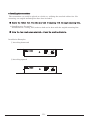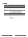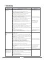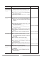
1
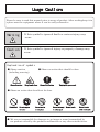
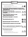
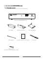
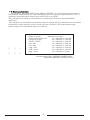
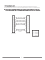
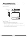
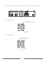
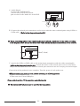
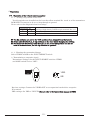
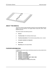
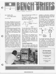
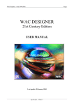
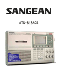
TWISTED PAIR TRANSMITTER
KE 0202CT2(w-type)
Instruction Manual
Thank you for your purchase of this product
Please be sure to read this manual completely prior to usage of product
Ver 2.5E
RGB Interface Cable
Use of a RGB interface cable longer than 3 m (9.84 feet) is not recommended.
For U.S.A
NOTE: This equipment has been tested and found to comply with the limits for
a Class A digital device, pursuant to Part 15 of the FCC Rules. These limits are
designed to provide reasonable protection against harmful interference when the
equipment is operated in a commercial environment. This equipment generates,
uses, and can radiate radio frequency energy and, if not installed and used
in accordance with the instruction manual, may cause harmful interference to
radio communications. Operation of this equipment in a residential area
is likely to cause harmful interference in which case the user will be required to
correct the interference at his own expense.
This device complies with part 15 of the FCC Rules.
Operation is subject to the following two conditions:
(1) This device may not cause harmful interference, and
(2) this device must accept any interference received, including interference
that may cause undesired operation.
For CANADA
This Class A digital apparatus complies with Canadian ICES-003.
Cet appareil numérique de la classe A est conforme à la norme NMB-003 du
Canada.
UsageCauti
on
s
Please be sure to read this manual prior to usage of product. After reading,keep it in
a place near the equipment where it can be easily referred to.
Warning
・If this symbol is ignored death or serious injury may
occur.
Caution
・If this symbol is ignored injury or property damage may
occur.
E
xp
la
n
a
ti
onofsymbols
● Shows caution
(including warning)
General caution
● Shows an action that should be done.
Keep hands clear
General indication
Unplug the power cord
● Shows an action that should not be done.
Prohibited
Do not expose
Do not use in
Do not attempt
to water
a wet place
to take apart
Do not touch
Do not touch
with wet hands
● We are not responsible for damages to an image or sound transmitted by
our product caused by the products malfunction or any other outside factor.
Warning
◆Do not continue to use this product if any of the following occurs
※It may cause fire or electric shock
・If you smell a strange odor or smoke.
・If water or a foreign object gets inside the product.
・After dropping the product.
・If the power cord is damaged. (exposure of core cable, severed cable)
■If any of the above should occur immediately turn the power off and
unplug the power cord. Contact the manufacturer or dealer who installed
this product for repair.
◆Do not place on an unsteady surface.
■Do not attempt to repair the product by yourself under any
circumstances.
※Do not place on a sloped or unstable surface.
It can cause serious injuries.
◆Do not use this product except for the specified
voltage and current (AC100∼240V).
※May cause fire or electric shock.
◆Do not stick any foreign objects into the product.
※May cause fire or electric shock.
◆Do not allow the product to get wet.
※May cause fire or electric shock.
◆Do not touch the power cord during a thunder storm.
※May cause electric shock.
◆Plug the product into an outlet that can be easily reached.
※Unplug the product if trouble occurs.
◆Be sure to completely insert the power cord plug into the outlet.
※Short circuiting or the generation of heat may cause fire or electric
shock. Do not connect many cords into one outlet.
◆Do not damage the power cord.
※May cause fire or electric shock.
・Do not modify the power cord.
・Do not pull or bend the power cord.
・Do not place a heavy object or this product on the cord.
・Do not place the power cord close to a source of heat.
Caution
◆Do not put this product in the following places.
※May cause fire or electric shock.
・Places where there is a lot of humidity or dust.
・Places where there is steam.
・Near places which generate heat.
・Places where water may come into contact with the product.
◆Turn off the power and follow all instructions ,
when connecting this product to other devices.
※Failure to use the recommended cables may cause generation of heat or fire.
◆Do not cover the ventilation holes.
※Doing so may cause the product to overheat, which can cause
fire or damage to the product.
・Do not leave the product laying on its side or turn it upside down.
※Do not cover the ventilation holes or stick foreign objects
into this product as it will cause damage.
◆Disconnect all cables before moving this product.
※The cables can be damaged and fire or electric shock may occur if
not disconnected.
◆Do not place a heavy object on this product.
※Placing a heavy or oversized object on the product may
cause injury as a result of it falling.
◆Disconnect the power cord when the product will not be used
for a long time.
※ Disconnect the power cord for safety purposes and to lower energy
consumption.
◆Unplug the product when servicing.
※Electric shock can occur even though the product is turned off
as current is still flowing from the power cord.
◆Do not unplug the device by pulling on the power cord.
※Pulling on the power cord may damage the cord or cause a fire or electric shock.
Please pull on the plug body.
◆Do not disconnect or connect the power plug with wet hands.
※May cause electric shock.
Index
1. About this product
1
1-1. Product and accessories
1
1-2. General information
2
2. Connection
3
2-1. The cautions and warnings
3
2-2. Preparation of cable
4
2-3. Cable mounting kit (Twisted pair transmitter)
5
2-4. How to connect
5
3. Denomination and function of each parts
3-1. Function of the twisted pair transmitter
9
9
3-1-1. Front panel of the twisted pair transmitter
9
3-1-2. Back panel of the twisted pair transmitter
10
4. Operation
4-1. Operation of the twisted pair transmitter
12
12
4-1-1. Setting a Dip switch on the base
12
4-1-2. Choosing the transmitted image
12
4-1-3. Mode switch settings
14
5. Installing the transmitter
15
6. Specifications
17
7. Trouble Shooting
18
Appendix
1. About this product (KE 0202CT2(w-type))
1-1. Product and accessories
Please check that you have the accessories and items shown.
KE 0202CT2
ON
1
POWER
VIDEO
GH
2
3
4
5
6
7
RGB
8
M.SW
INPUT SELECT
TWISTED PAIR TRANSMITTER
Main unit of KE 0202CT2(w-type)
AC adapter
Angle mounting kit×2
Cable mounting kit
TWISTED PAIR TRANSMITTER
KE 0202CT2(w-type)
User's manual
Fixing band×2
Instruction Manual(This booklet)
Wood screw×4
(Screws for underdesk, wall or ceiling)
-1-
Power cord
1-2.General information
The products, KE 0202CT2W (w-type)/KE 0101CR-BW, are a transmitter and receiver for
long distance transmission of a wide band signal such as a computer, high definition TV or a
composite signal through a twisted pair cable (CAT5 e or CAT6).
They also have the function of long distance transmission of stereo sound and RS232C
serial data.
The minimum recommended transmission range is 10m(32.8ft). The maximum recommended
transmission range depends on the refresh rate and resolution. The transmission range
(when using our recommended cable) is as follows.
Name of signal
Transmission range
Audio signal/serial data
:10∼300m(32.8∼984.2ft)
Composite signal
:10∼300m(32.8∼984.2ft)
YPbPr/YCbCr
:10∼300m(32.8∼984.2ft)
640×480
:10∼200m(32.8∼656.1ft)
800×600
:10∼180m(32.8∼590.5ft)
1024×768
:10∼150m(32.8∼492.1ft)
1280×1024
:10∼120m(32.8∼393.7ft)
1600×1200
:10∼100m(32.8∼328ft)
Recommended cable : OKTP-E5-P-AWG24x4P
(OKANO ELECTRIC WIRE CO.,LTD)
-2-
2. Connection
2-1.The cautions and warnings.
◆Cautions
・ Use the recommended cable for this product for best results.
(OKANO ELECTRIC WIRE CO.,LTD: OKTP-E5-P-AWG 24x4P)
When a cable other than the recommended cable is used, make sure that the characterisitcs
and functionality of the cable is fully understood before use.
・When cable length is longer than the recommendation distance indicated in the
"product outline", quality of the image may deteriorate.Please note that use beyond
the recommended distance will require outside support.
・If a twisted-pair cable is laid near a power supply line with a lot of noise,
the image may flicker. In this case, run the twisted-pair cable away from the power supply
line.
・If the product is connected to an AC power supply with noise, the image may flicker.
In this case, use an AC wall socket type noise filter.
・Use the cable mounting kits, when weight will be applied to the twisted pair connectors of the
transmitter. (Please refer to "2-3. Cable mounting kit (Twisted pair transmitter)").
◆Warnings
・Do not connect any unauthorized product to the extension input/output connectors of the
twisted pair transmitter or receiver, as it can cause damage to the products.
Kowa is not responsible for any damage or injury caused as a result of improper use.
・Turn off the transmitter, receiver, and any product that is connected to the devices when
removing or installing twisted pair cables. Failure to do so can cause damage or failure
of the products.
-3-
2-2.Preparation of a cable
A CAT5e or CAT6 cable is used to connect the twisted pair transmitter and receiver.
The transmitter and receiver are connected straight through as shown in the diagram below.
※ Please keep the combination of the pair lines as follows. If the combination of a pair line
is incorrectly installed , there is a possibility that the quality of the image may deteriorate.
1
1
2
2
3
3
4
4
5
5
6
6
7
7
8
8
Cables
Connector
Connector
1,2…pair 1
3,6…pair 2
4,5…pair 3
7,8…pair 4
-4-
2-3. Cable mounting kit (Twisted pair transmitter)
A mounting kit for the twisted-pair cable is enclosed with the twisted pair transmitter.
Use the following diagram to attach the mounting kit.
Diagram for attachment
Cable mounting kit
RGB IN
RGB OUT
Pr
Y/VIDEO
IN
Pb
Cable mounting kit
DC12V IN
AUDIO IN
L
R
AUDIO OUT
L
Pr
R
OUT
Y/VIDEO
Pb
FG
RS-232C
Cable mounting kit
KE 0202CT2
ON
1
POWER
VIDEO
GH
2
3
4
5
6
7
RGB
8
M.SW
INPUT SELECT
TWISTED PAIR EXTEND TRANSMITTER
2-4. How to connect
Connect the receiver according to the following procedures.
Ⅰ.Check that all of the devices (PDP(Plasma Display Panel), video, a DVD player,
PC, display, etc.) to connect are turned off.
◆ Warning
・Even when the PDP is turned off, power is being supplied to the twisted pair receiver.
Be sure to unplug the power supply cable of the PDP.
-5-
Ⅱ.Refer to the following diagrams when connecting cables to the twisted pair transmitter.
⑨
AUDIO IN
L
⑩
R
AUDIO OUT
L
④
R
Pr
⑧
OUT
Y/VIDEO
⑦
RS-232C
FG
Pb
DC12V IN
RGB IN
RGB OUT
Pr
Y/VIDEO
IN
①
②
③
Pb
OUT 1
OUT 2
⑤
⑥
a).Composite signal
Connector ④
Output of composite(for monitering)
Pr
Pr
OUT
Y/VIDEO
Y/VIDEO
IN
Pb
Pb
Input of composite
Connector ③
b).Component signal
(for monitering) Connector ④
Pr output Y output Pb output
Pr
Pr
OUT
Y/VIDEO
Pb
Y/VIDEO
IN
Pr input
Pb
Y input
Connector ③
-6-
Pb input
c).RGB signal
Connector ②
Connector ①
RGB IN
RGB OUT
RGB Output(for monitering)
RGB Input
d).Audio signal
Connector ⑩
Connector ⑨
AUDIO IN
L
Input L
R
Input R
AUDIO OUT
L
R
Output L Output R
(for monitering)
Ⅲ.Refer to the following diagrams when connecting cables to the twisted pair receiver.
①
②
a).Composite signal
Connect the "VIDEO OUT "of the twisted
pair receiver to the "VIDEO IN"
of the PDP.
Back panel of PDP
Connector ①
VIDEO OUT
-7-
VIDEO IN
b). Audio Signal
Connect the "AUDIO OUT"
( Stereo mini jack) of the twisted
pair receiver to the "Audio In" of the PDP.
Back panel of PDP
Connector ②
AUDIO OUT
R
AUDIO
IN
L
Ⅳ.Connect the twisted pair transmitter and receiver with the correct twisted pairs using CAT5e or
CAT6 cable. ( Refer to the diagram in section 2-2)
※ When connecting cables to the connectors,be sure to attach a ferrite core to the cables according
to the diagram below. Attach the ferrite core within 20cm(7.8inch) from the bottom of the receiver.
SLOT1
20cm(7.8inch)
Ⅴ.Attach the CAT5e or CAT6 cable to the twisted pair transmitter with the cable mounting kit
(refer to the diagrams in section 2-3) . Attach the cables of the twisted pair receiver to the main
body of the PDP and make sure that the twisted pair connectors are not carrying too much weight.
Connection of the products is now complete. Turn the power of each product on.
※Please turn on the power of each product according to following process.
1.Turn on a transmitter,first.
2.Then,turn on a Plasma Ddisplay.
Please refer to section "4" for operation and adjustments.
※ The enclosed AC adapter must be used for the transmitter.
-8-
3.Denomination and function of each parts
3-1.Function of the twisted pair transmitter
3-1-1.Front panel of the twisted pair transmitter
KE 0202CT2
ON
1
POWER
GH
2
3
4
5
M.SW
6
7
8
VIDEO
RGB
INPUT SELECT
TWISTED PAIR EXTEND TRANSMITTER
①
②
③
① POWER
After connecting the adapter cable the power will turn on and the power indicator lamp
will light up.
② M.SW
Dip switch No.8 switches between composite and component signals.
③ INPUT SELECT
This switch determines if the image output to Connector 1 and 2 is VIDEO or RGB.
-9-
3-1-2.Back panel of the twisted pair transmitter
⑨
AUDIO IN
L
⑩
R
AUDIO OUT
L
④
R
Pr
OUT
Y/VIDEO
⑦
⑧
RS-232C
FG
Pb
DC12V IN
RGB IN
RGB OUT
Pr
Y/VIDEO
IN
①
②
③
Pb
OUT 1
OUT 2
⑤
⑥
① RGB IN
High density D-SUB 15pin : Connector for image input
This is the input connector for RGB signal (Not available for GonSYNC)
※ Please use a cable under 3m (9.84feet) in length when connecting.
② RGB OUT
High density D-SUB 15pin: Connector for image output: for monitoring
An RGB IN signal can be outputted through the RGB OUT connector for monitoring,
regardless of the dip/toggle switch settings, as long as the transmitter is turned on (signal buffer
requires power).
※ Please use cable under 3m (9.84feet) in length when connecting.
③ Pr IN, Y/VIDEO IN, Pb IN
RCA Pin jack: Connector for image input.
This is an input connector for component or composite signals.
For a composite signal use the VIDEO IN connector.
④ Pr OUT, Y/VIDEO OUT, Pb OUT
RCA Pin Jack: Connector for image output : for monitoring
(Pr, Y/VIDEO, Pb) IN signals can be outputted through the (Pr, Y/VIDEO, Pb) OUT connector
for monitoring, regardless of the dip/toggle switch settings, as long as the transmitter is turned on
(signal buffer requires power).
⑤ OUT1,OUT2
RJ-45 connector : output connector for twisted pair cable for extension.
This is connected with a CAT5e or CAT6 cable to the receiver.
2 points of distribution.
◆Warning
・Do not connect to any other receiver as it may cause fire or other damage.
-10-
⑥ DC12V IN
It could be plugged an 12V dedicated voltage adapter.
⑦ FG
Frame ground
Connect a ground wire to the transmitter.
⑧ RS-232C
Serial communication for RS232C (transmission only).
D-SUB 9pin (male) is necessary.
Uses a RS-232C Straight cable.
(Please refer to the appendix for details)
⑨ AUDIO IN
RCA pin jack: connector for audio input
The input connector for audio. (Stereo L,R)
⑩ AUDIO OUT
RCA connector : output connector for sound : for monitoring
An AUDIO IN signal can be outputted through the AUDIO OUT connector for monitoring,
regardless of the dip/toggle switch settings, as long as the transmitter is turned on (signal buffer
requires power).
-11-
4.Operation
4-1.Operation of the twisted pair transmitter
4-1-1.Setting a dip switch on the base
Two dip switches are installed on the base that allow terminal No. 4 and 11 of the transmitter.
RGB IN/OUT connector to be set to loop through or ground.
Please refer to the diagram below for settings.
Dip Switch No.
1
2
off
off
on
on
Setting of high density D-SUB 15-pin terminal No. 4,11
Loop through
Ground
※ The dip switches are set in the "Off" position when shipped from the factory.
※ Please switch both No.1 , 2 dip switches on the base when changing the setting.
※ Normally use the setting "loop through".In the event that pictures can not be
seen on some monitors, set the dip switches to "ground".
4-1-2.Choosing the transmitted image
Select VIDEO or RGB on the INPUT SELECT switch.
a).Transmitting a composite signal
Transmitter settings: Set the INPUT SELECT switch to VIDEO
and M.SW switch No.8 to "OFF".
ON
1
GH
2
3
4
5
6
7
VIDEO
8
M.SW
RGB
OFF
8
Receiver settings: Connect the VIDEO OUT to an expansion board with a composite
IN terminal.
PDP settings: Set PDP to "INPUT2"(Please refer to the instruction manual of PDP)
-12-
b).Transmitting a component signal
Transmitter settings: Set the INPUT SELECT to VIDEO
and M.SW No.8 to "ON".
ON
1
GH
2
3
4
5
6
7
VIDEO
ON
8
M.SW
RGB
8
PDP settings: Select "INPUT 1"and on the PDP screen menu, select "component"
from the "component/RGB" options (Please refer to the instruction manual of the PDP).
c).Transmitting an RGB signal
Transmitter settings : Set the INPUT SELECT switch to RGB.
※ M.SW No. 8 can be set to either On/Off
VIDEO
RGB
PDP settings: Select "INPUT 1"and on the PDP screen menu select "RGB"
from the "component/RGB" options. (Please refer to the instruction manual of the PDP).
-13-
4-1-3.Mode switch settings
The M.SW switches can be set as follows.
Dip switch No.
1
2
3
4
5
6
7
8
A detail of setting
Reserved
〃
〃
〃
〃
〃
〃
Switching between composite (OFF) and component
(ON) signals. ※ INPUT SELECT switch is only
effective when set to VIDEO
※ All M.SW switches are set in the "Off" position when shipped from the factory.
-14-
5.Installing the transmitter
The transmitter can easily be placed on a desk, etc. utilizing the attached rubber feet. For
mounting, two angled mounting kits have been included.
※ Remove the rubber feet from the main body if mounting with the angle mounting kits.
a) Installing on a flat surface
Installation on a ceiling, wall, under a desk can be done with the angled mounting kits.
※ Using the four wood screws provided, attach the mounting brackets.
Installation Examples
① Attaching downward
KE 0202CT2
ON
VIDEO
GH
1
2
3
POWER
4
5
6
7
RGB
8
M.SW
INPUT SELECT
TWISTED PAIR EXTEND TRANSMITTER
② Attaching upward
KE 0202CT2
ON
1
GH
2
3
POWER
4
5
M.SW
6
7
8
VIDEO
RGB
INPUT SELECT
TWISTED PAIR EXTEND TRANSMITTER
-15-
b) Attaching to a rack
1U x 1 rack mount set
1U x 2 rack mount set
Using the above mount kits allow the transmitter to be attached to a rack. The mount kits are
the same color as the casing of the transmitter giving the outside an aesthetically pleasing look.
The rack mounts are optional accessories. Contact us if you would like to place an order.
One unit rack mount
KE 0202CT2
ON
1
VIDEO
GH
2
3
POWER
4
5
6
7
RGB
8
M.SW
INPUT SELECT
TWISTED PAIR EXTEND TRANSMITTER
Two unit rack mount
KE 0202CT2
ON
1
POWER
VIDEO
GH
2
3
4
5
6
7
RGB
8
M.SW
INPUT SELECT
TWISTED PAIR EXTEND TRANSMITTER
KE 0202CT2
ON
1
POWER
GH
2
3
4
5
M.SW
6
7
8
VIDEO
RGB
INPUT SELECT
TWISTED PAIR EXTEND TRANSMITTER
Cautions:
The temperature inside the rack must not exceed 40℃.
Do not cover the ventilation holes of the transmitter.
Secure the mounting brackets to the transmitter and the rack using the supplied machine
screws.
Loads other than the transmitter must not weigh on the mounting brackets.
The power cord and AC adapter must be used in the rating.
-16-
6.Specification
Model name
Number of input
channels
Number of output
channels
KE 0202CT2(w-type)
Image (RGB, VIDEO) each 1 system, Audio 1 system or RS-232C 1 system
Output for monitor (RGB, VIDEO, Audio) each 1 system, Output for
extension 1 system (2 distribution)
Input connector
D-SUB 15pin : RGB, RCA pin jack : Component,Composite,
RCA pin jack: Audio, D-SUB 9 pin : RS-232C
Output connector
D-SUB 15 pin : RGB, RCA pin jack : Component,Composite,
RCA pinjack : Audio, RJ-45 connector : Output for extension
Interface cable for extension
Enhanced CAT5 cable , CAT6 cable
Image input and output
signal
Analog Y/Y : 1Vp-p (75Ω), Pb・Pr/Cb・Cr : ±0.35Vp-p(75Ω),
RGB : 0.7Vp-p(75Ω), HD・VD : TTL, VBS/VS : 1Vp-p(75Ω)
Audio input and output
signal
Input: -10dBu 50kΩ, Output: -10dBu loading over 10kΩ
Temperature and humidity
operating conditions
Temperature: 0~40℃ Humidity: 20~80%(no condensation)
Power source
Power consumption
A dedicated AC adapter DC12V
Approximately 10W
Power (AC adapter)
Input:AC100-240V 0.3A 50-60Hz Output:DC12V 1A
Dimension
W210×D126×H44(mm) [W8.3×D4.9×H1.7(inches)] ※Dimension excludes
connectors,etc.
Weigh
Approximately 1kg [2.2lbs]
-17-
7.Trouble Shooting
Problem
Reference
Please check the following
The image can't be seen ● Is the power of PDP turned on ?
on the PDP
● Is the lamp of the twisted pair transmitter lit-up?
Is the power adapter cable properly connected to AC90-264V
line and a twisted pair transmitter?
● Is there a source that causes noise near the cables?
A noise filter should be used in case of noise.
● Is the CAT5e or CAT6 cable properly connected to OUT 1 or
OUT2 of the twisted pair transmitter?
● Is the CAT5e or CAT6 cable connected to OUT1 or OUT2 of
the twisted pair transmitter carrying weight?
● Is the cable properly connected to the RGB IN connector or
(Pr,Y/VIDEO,Pb) IN connector of the transmitter?
● Are the M.SW switches of the transmitter properly set?
● Is the INPUT SELECT of the transmitter properly set?
Please refer to a
instruction manual of PDP
−
−
−
→2-3.Cable mounting kit
(Twisted pair transmitter)
−
→4-1-3.Mode switch
settings
→4-1-2. Choosing the
transmitted image
● Is the LED (near side of Volume) IN connector of the receiver −
lit? Was it properly placed into the PDP slot?
● Did you adjust a LEVEL /PEAKING of a twisted pair receiver? −
The image of PDP is
flickering or there is
noise
● Are the cables properly connected to the IN connectors?
● Is the length of the cable within the recommended transmission
range?
● Are the cables wired correctly?
● Is a switch of input for PDP properly done? Switching should
be done by an attached remote control.
−
→1-2.General information
● Is the twisted pair cable near the AC line? It should be far
from the line.
● Is there a source causing noise close to AC adapter of the
twisted pair transmitter? A noise filter should be used in case
of noise.
● Is the CAT5e or a CAT6 cable properly connected to OUT 1 or
OUT2 of the twisted pair transmitter?
● Is the CAT5e or CAT6 cable connected to OUT1 or OUT2 of
the twisted pair transmitter carrying weight?
● Is the cable properly connected to RGB IN connector or
(Pr,Y/VIDEO,Pb) IN connector of transmitter?
● Did you adjust a LEVEL/PEAKING of a twisted pair receiver?
−
● Are cables properly connected to IN connectors?
● Is the cable properly connected to the IN connector of twisted
pair receiver?
● Is the length of cable within the recommended transmission
range?
● Is a switch of input for PDP properly done? Switching should
be done by an attached remote control.
The image of a RGB
signal can't be seen
in MONITOR OUT
of the transmitter
→2-2.Preparation of cable
Please refer to a
instruction manual of PDP
−
−
→2-3.Cable mounting kit
(Twisted pair transmitter)
−
−
−
→1-2.General information
→4-1-2.Choosing the
transmitted image
Please refer to a
instruction manual of PDP
● Is the lamp of the twisted pair transmitter lit?
−
Is the power adapter cable properly connected to AC90-264V
line and a twisted pair transmitter?
● Is there a source that causes noise close to the outlet of the −
twisted pair transmitter?
● Is the cable properly connected to the RGB IN connector of −
the twisted pair transmitter?
-18-
The image of composite ● Is the lamp of the twisted pair transmitter lit? Is the AC
or component signals
adapter cable properly connected to AC90-264V line and
can not be seen in
a twisted pair transmitter?
MONITOR OUT of the ● Is there a source that causes noise close to AC adapter of the
transmitter
twisted pair transmitter? A Noise filter should be used.
● Is the cable properly connected to IN connector(Pr,Y/VIDEO,Pb)
of the twisted pair transmitter?
● Is the cable properly connected to OUT connector(Pr,Y/VIDEO,Pb)
of the twisted pair transmitter?
−
−
−
−
Sound can not be output ● Is the power of PDP turned on?
from PDP
● Is the lamp of the twisted pair transmitter lit? Is the AC adapter
cable properly connected to AC90-264V line and a twisted pair
transmitter?
● Is there a source that causes noise close to the AC adapter of the
twisted pair transmitter? A noise filter should be used in case of
noise.
● Is the CAT5 or CAT6 cable properly connected to OUT 1 or OUT2
of the twisted pair transmitter?
● Is the CAT5 or CAT6 cable connected to OUT1 or OUT2 of the
twisted pair transmitter carrying weight?
● Is the cable properly connected to the AUDIO IN connector of
the twisted pair transmitter?
● Is the LED (near side of Volume) IN connector for the twisted
pair receiver lit? Is it properly installed into the PDP slot?
● Is the cable properly connected to the IN connector of the twisted
pair receiver?
● Is the length of cable within the recommended transmission
range?
Please refer to a instruction
manual of PDP
Sound of PDP has noise ● Is the twisted pair cable near AC power line? It should be
far from the line.
● Is there a source that causes noise close to the AC adapter
of the twisted pair transmitter? A noise filter should be used
in case of noise.
● Is the cable properly connected to OUT 1,OUT2 of
the twisted pair transmitter?
● Is the CAT5 or CAT6 cable be connected to OUT1 or
OUT2 of the twisted pair transmitter carrying weight?
● Is the cable properly connected to AUDIO IN connector of the
twisted pair transmitter?
● Is the cable properly connected to AUDIO OUT connector of
the twisted pair receiver?
● Is the length of cable within the recommended transmission
range?
−
Sound can not be output ● Is the lamp of the twisted pair transmitter lit?
from monitor out of the
Is the cable for the AC adapter properly connected to AC90-264V
transmitter
line and the twisted pair receiver?
● Is the twisted pair cable near the AC power line? It should be
far from the line.
● Is the cable properly connected to AUDIO IN connector of the
wisted pair transmitter?
● Is the cable properly connected to AUDIO OUT connector of the
twisted pair receiver?
−
-19-
−
−
−
→2-3.Cable mounting kit
(Twisted pair transmitter)
−
−
−
→1-2.General information
−
−
→2-3.Cable mounting kit
(Twisted pair transmitter)
−
−
→1-2.General information
−
−
−
Appendix
Ⅰ.Wiring diagram for RS232C
Connection between a computer and the transmitter
The RS232C straight cable of D-SUB 9pin can be used. (Both ends are female connectors)
Computer (D-SUB 9pin)
Pin No.
1
2
3
4
5
6
7
8
9
Transmitter (D-SUB 9pin)
Name of signals
Pin No.
Name of signals
1
2
3
4
5
6
7
8
9
NC
TXD(Transmitted data)※No data sending
RXD(Received data)
Shorted to 6
GND(Ground)
Shorted to 4
Shorted to 8
Shorted to 7
NC
DCD(Data carrier detect)
RXD(Recived data)
TXD(Transmitted data)
DTR(Data terminal ready)
GND(Ground)
DSR(Data set ready)
RTS(Request to send)
CTS(Clear to send)
RI(Ring Indicator)
Ⅱ.Requirement for communication
Signal level
RS-232C compliant
Synchronization method
Asynchronous
Baud rate
9600bps
Character length
8bit
Parity
None
Stop bit
1bit
Flow control
None
Ⅲ.Basic format control data(when using a twisted pair transmitter)
STX
"AD95;"
Bit position
":"
Command
Details
Parameter(s)
ETX
Bite length Note
0
STX(0x02)
1
The transmission of control data starts with a STX signal.
1
"AD95;"
5
A semicolon ( ; ) is required after "AD95".
6
[Command]
3
Refer to a list of "command".
9
":"
1
A colon( : ) is unnecessary when a parameter is "None".
10
[Parameter]
Un-specified ETX(0x03)
Variable
1
There is a command which does not need a parameter.
The transmission of control data ends with a ETX signal.
Ⅳ.List of "Commands"
Command Parameter
PON
None
POF
None
AVL
**
AMT
0
1
IMS
None
SL1
SL2
SL3
PC1
DAM
None
NORM
ZOOM
FULL
JUST
SELF
Control details
Power ON
Power OFF
Volume 00∼63
Audio mute OFF
Audio mute ON
Input select(toggle)
Slot1 input
Slot2 input
Slot3 input
PC input
Screen mode select(toggle)
4:3
ZOOM
16:9
JUST
Panasonic AUTO
※1. When two or more commands are to be transmitted,
transmit subsequent commands only after operating PDP
completely by the previous command.
※2. No commands can be executed while the Power is OFF
except for the "PON" command.
※3. Keep in mind that "AD95;" is required for the
transmission of control data when controlling the PDP using
the twisted pair transmitter/receiver.
※4. Any response from PDP can not be transmitted when
using the twisted pair transmitter/receiver. -Appendix-
2005.09.22
※ Design and specifications are subject to change without notice.