Transcript
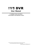
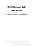
7. Access the device:
8. Device setting:
Device Name – You may assign the device a name so it will be easily recognizable
once connected to a computer. The device name will also be shown on the Time
Stamp when that option is enabled.
Clock Setting – The device date and time may be set manually by clicking on the
first radio button and changing the date and time settings. Alternatively, you may
select the second radio button to allow the device to sync its date and time settings
with those on the computer to which it is currently attached. Neither time setting will
be put into effect until the “Save” button has been clicked, please keep this in mind
especially when setting the time manually.
The iPower Canera comes with user interface (UI) software for setting up your
preferences and options, as well as providing secure access to your video and photo
files. It runs directly from the device without installing on the computer. You must login
in to access the settings menu, as well as gain access to the second, secure drive
containing the recorded files.
1.With the device connected to a computer using the included USB cable, switch the
device into Standby Mode.
2.The first time you attach the device to a computer, the computer will detect a new
device and load the drivers. Once complete, open the newly installed disk in Windows
Explorer(My Computer) to view the files and you will see the following screen:
UI
1.To access the video and picture files, you must first login to gain access to the
second, secure drive containing the files. See “Accessing the Device” above.
2.Once you have logged in and opened the secure drive in Windows Explorer,
navigate into the DCIM folder and then again into the 100MEDIA folder.
Recording Preferences:
User Manual
3.Double-click on the Power Case DVR UI application to open and run it.
4.The password box will appear:
a.Click on Refresh Drives
b.A list of drives will appear in the drop down list to the right. Select the one that
matches the drive where the UI application was found. In our example, it is drive F:\
c.The default password is 00000000. You may change your password in the setup,
but please remember to save it somewhere for future reference.
d.Click Login and click OK on the ‘Password OK’ popup box to enter the settings UI.
5.Once login is complete, the setup menu will appear and the secure drive will now
be accessible through Windows Explorer.
9. File Access and Management:
When navigating the User Interface, you may choose to make single or multiple
changes in one pass. Once you have completed all desired changes, click the
“Save” button at the bottom of the UI.
Password Change – If you wish to change the default password, you may do
it here. The password must be exactly 8 characters in length and may include any
combination of letter, characters and or numbers. Enter your desired password into
the “New Password” field and again in “Confirm New Password.” Both fields must
match for the new password to be saved.
(4)
Video Resolution – Select the radio button by 2000P (Option), 1080P or 720P for
your preference of video recording resolution.
Audio – Have the option to turn on or off the audio
Video Overwrite – When the memory has reach its capacity, you may choose to have
the device either stop recording or continually delete the oldest file and replace it with
a new one. To stop recording and retain all files, select the radio button by “Disable”;
to continue recording and overwrite the older files with newer ones, select the radio
button by “Enable.”
Video File Length – The video files are managed by maximum length of the recording.
You may select 5, 15 or 30 minute durations. Once a recording has reached that time
limit, the recording will stop, be saved in the memory and a new recording will begin
at the prior ending point. If the Mode Switch is moved out of Record before that time
limit, the recording will stop at that point in time and save to the memory. If the memory
is approaching capacity and Video Overwrite is disabled, the recording will be cut
short and saved such that the file will fit in within the remaining memory.
Photo Resolution – The photo resolution is managed by the number of Megapixels.
You may select 3, 5, 8 or 12 Megapixel resolutions.
Photos taken per Press – Either 1 or 3 photos can per taken by the device per single
press of the Multi-function Button when the Mode Switch is in Standby.
Vibration Alert – This option toggles whether the device will vibrate when switching
modes or not. The device will always vibrate when power is low.
On – The device will vibrate when entering Standby and Record modes and when
switching Low Light mode ON or OFF while in Record mode.
Off – The device will only vibrate to alert that the battery is low.
Date/Time Stamp – Enabling this option will place the date and time, from Clock
Setting, into video recordings and photos taken by the device.
(5)
(6)
1. 3MP Camera Sensor
2. Power/Record Button
3. Night Mode Button
6
4. Mini USB Port
3. Charge the battery
a. Connect the device to PC or a USB wall charger via the
attached USB Cable while the device is OFF
b.One blue LED on the back button wil light on while
charging, once finish the charge the LED goes off.
5. Three Indication LED’s
7
(7)
5. Operation:
1. Names and parts
iPower 1080p / 2000p Hidden Camera
Model: OC-A7-i5(s) 01 / 03
Operation Manual
3.Once inside both folders, you may directly manage your files here.
a.Double-click any file to view/play your recordings
b.Drag and drop or right click to save them in another location.
c.You may delete files from the device memory.
4.When finished accessing the files, remember to always disconnect device within
Windows using the Safely Remove Hardware function on your computer. Failure
to do so may corrupt the devices storage and void the warranty.
Mode Switch (A) has 3 positions
1.Off – To turn the device off, slide the switch all the way up to the OFF position.
All LED lights will turn off, confirming power-down is complete.
2.Stand-By – To place the device in Stand-By mode, slide the switch to the middle
position. The left-side status LED will stay lit, confirming the device is in Stand-By
mode. If Vibration Alert is enabled, it will also vibrate once when entering this mode.
3.Record – To place the device in Video Record mode, slide the switch from the
middle (Stand-By) down to the final position. The left-side status LED will now
intermittently flash, confirming the device is in Record mode and currently recording
video. If Vibration Alert is enabled, it will also vibrate once when entering this mode.
6. Photo / Power & Memory
Level Button
2
4
5
1
3
7. Reset Button
2. Specification
Camera sensor:
1/3.2” CMOS ,3 Mega Pixels
Low Light Sensitivity:
1900 mV/lux-sec (550nm)
Lens:
Video Resolution:
F2.7 / 3.4 mm / 4G(Optical)
2000p@30(Option)1080p@30fps, 720p@30fps
Field of Angle:
120 degree
Photo Resolution:
3 (Real), 5, 8, 12 Megapixels
Video / Photo File Format:
Video:MOV, Photo: JPEG
Power Life Time:
3 hours ± 5%
Battery Capacity:
Lithium 1200mA/3.7V
Battery Charge Time:
4 hours
Out to PC:
USB2.0
Standard Built-in Memory:
Operating Switcher A:
32 GB
Power Off/ Power On/ Recording
Operating Switcher B:
Vibration Alert:
4. Power & Memory Level Indication
then push & hold the back button until
the circled LEDs’ light on, firstly show
the power level status, secondly show
the memory level status, one LED
stands left 20~30% while two
LED’s mean left 50~60% & 3 LED’s
light on is 90~100% full.
Night Mode Off / Night Mode On
Recording/ Photo Taking/ Weak Power
Weight / Dimension:
72g / 185×61×17 mm
Power 3 Level Indication:
100~60% / 60~20% / 20~5%
Beyond Science
(1)
V1.0
(2)
Low Light Switch (B) has 2 positions
1.Low Light Off
2.Low Light On – For best results, turn this function on prior to entering a dark
area. If a video is currently recording and the switch moved either direction, it will
stop the current file and start a new one.
Middle Button has 2 functions
1.Still Photos – With the Mode switch set to Stand-By, press and release the
button once to take a photo.
2.Battery & Memory Level – With the Mode switch set to Stand-By, press and hold
the button for approximately 2 seconds. The first set of LED’s will indicate the battery
power level, then all lights will turn off. Immediately after the lights turn off, the next
set of LED’s will indicate the free memory level, then return to the single LED confirm
the device is in Stand-By mode. List below applies for both Battery and Memory indicators.
a.1 LED – 20-30% remaining
b.2 LED’s – 50-60% remaining
c.3 LED’s – 90-100% remaining
(3)