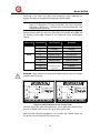
1
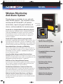
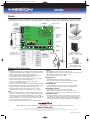
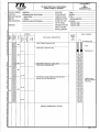
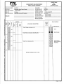
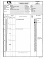
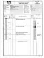
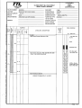
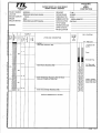
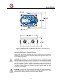
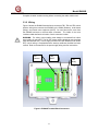
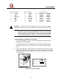
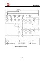
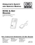
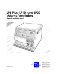
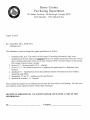
DataSheet M110_v18.qxd 6/10/09 11:31 AM Page 1 MODEL M-110 Series C O M M U N I C A T I O N S Wireless Monitoring And Alarm System Simpler than an autodialer to use, and with many SCADA features. The complete system includes the M-110 field RTU, all wireless connections, report and graph software, all alarms, and two websites for remote access. Flatpak NEMA1 Enclosure Option Shown One M-110 Is a Complete Wireless Monitoring System Each M-110 includes a field RTU, wireless communications through cellular data, MISSION based computers and software, amazing alarm notifications, and two customer websites. The whole system is up and running in a few hours. Customer has no computers or networks to maintain! The M-110 RTU Comes With Everything You Need Each RTU has 8 digital inputs (plus 4 built-in), 2 analog, 2 pulse counter (optional), and 1 key reader inputs; 3 remotely controllable relay outputs. Optionally expand to 6 analog or 16 digital inputs. It also includes a radio, enclosure, antenna, antenna cable, power supply, and backup battery. Remarkable Wireless Coverage and Reliability The M-110 uses the data side of any cellular system, not the part you talk on. It works reliably even where your voice cell phone doesn’t, and with multiple cell carriers available to it MISSION can make almost any site communicate reliably. • One M-110 Is a Complete Wireless Monitoring System • The M-110 RTU Comes With Everything You Need • Remarkable Wireless Coverage and Reliability Centralized Web Software and/or Direct Into Yours MISSION’s web based software is very simple; we set it up for you and upgrades are included and automatic. Send your data directly into your existing HMI software like Wonderware® or Intellution®. • Centralized Web Software and/or Direct Into Yours Full Suite of Cost Saving Software Features It tracks hourly run times and starts, graphs them, analyzes them and calls you if there’s a problem. False alarm suppression features and real time data during alarms saves time and money. Flexible Alarm Notifications, Tracked to Alarm Site Alarms can be delivered via voice phone calls, all pagers, email, fax, or OPC. Full alarm dispatch logs track and record every call. Electronic RTU service keys log personnel site arrival and maintenance times. Website Provides Remote Data Access and Reports Customers get their own secure web sites to view data anywhere, including in the field through cell phones. Data for CMOM/State/EPA reporting is all there. • Full Suite of Cost Saving Software Features • Flexible Alarm Notifications, Tracked to Alarm Site • Website Provides Remote Data Access and Reports DataSheet M110_v18.qxd 6/10/09 11:31 AM Page 2 MODEL M-110 Series Details MISSION uses AT&T/Nextel/Sprint/Verizon and centralized computer services to offer a revolutionary, real-time monitoring and control SCADA system. It can also economically replace or complement existing radio or phone line based SCADA systems. AC input from Transformer leads (included). 120 VAC to 12 VAC Optional Connector Board Carrier LED (solid green indicates unit is online) 12 VAC Input From Transformer 12 VDC battery (included) 12 VDC Batt. Input 18 - 14 Gauge 12 VDC Aux. Transducer power out 12 VDC Aux. Output Radio/Daughterboard Assembly Carrier Data 689MISXXXX Radio Status LED (should blink slowly when online) DB 9 Serial Port 2 Wire Analog Transducer Transducer Output RJ45 Plug for Wet Well Module Cable Outdoor NEMA 4X enclosure: Top and front sun shield 13.75"h x 13.25"w x 6.25"d (with sun shield) Status LEDs + – OR – Buzzer/ Sounder output + To analog output ± – from PLC Antenna Connection Default Assignments Inputs default to normally open. Use dry contacts only! NO common wire used on loop. Pump 1 Runtime or Alarm Panel Open or Other Alarm Pump 2 Runtime or Alarm 3 Phase Trouble or Other Alarm Pump 3 Runtime or Alarm Pump 2 Trouble or Other Alarm High Wet Well Level or Other Alarm Pump 1 Trouble or Other Alarm Output relays. Typically used in conjunction with low voltage interposing relays to remotely turn pumps on and off. Keyreader input Pole or Wall Mount Technical Specifications Hardware: • 8 supervised digital inputs; 3 changeable to runtime/starts accumulators. 4 additional built-in alarms (AC, low battery, and communications fail, input wiring fault). Optionally expand to 16 digital inputs. • 2 analog inputs: 0-5 VDC, 4-20mA, 10-bit resolution, 4 alarm set points per input. Option board expands analogs to 6. • 2 pulse counter inputs (optional): rainfall or flowmeter or reading. • 1 electronic key reader for site activity tracking. • 3 remotely controllable, form C dry contact relay outputs (1 amp @ 12 VDC), SPDT, N.O./N.C. • Supervised 1.2 amp power supply with 5AH battery backup included. • 8 vertical LEDs have two display modes: diagnostic or signal strength. • 8 digital input LEDs display alarm status and wiring faults. • Includes Antenna Kit with mounting bracket and 11' of cable. Omnidirectional outdoor antenna can be wall or pole mounted. Radio: • Units automatically self enroll, no startup delays. Radios make live, continuous, encrypted socket connections with all data and alarms being “end-to-end” acknowledged. MISSION does not use SMS “text” messaging for any communications with the M-110 or M-800. • AT&T, Nextel, Sprint, or Verizon radios, all with 128 bit encryption, and all using the data transmission protocol. • 0.6 to 2 watt maximum transmit power and -112dBm sensitivity. NEMA1 enclosure: 11.25"h x 11.375"w x 3.5"d Use indoors, wall mounting Flatpak NEMA1 enclosure: 7.75"h x 10.5"w x 1.5"d Use inside MCC cabinet Physical: • M-110 NEMA1 enclosure: 11.25"h x 11.375"w x 3.5" • M-112 NEMA 4X enclosure, with sun shield: 13.75"h x 13.25"w x 6.25"d • M-113 NEMA1 “FlatPak”: 7.75"h x 10.5"w x 1.5"d • Operating temperature –20F° to +160F° MISSION Control: • All MISSION facilities secured and redundant. • Data center links real-time with existing SCADA HMI software (Wonderware, Intellution, etc.) that is OPC compliant. MISSION Website: • Two websites: full size screens and one for cell phones/PDAs. • Read only, read/write and control level access by password. MISSION Web Software: • Very simple; no programming; upgrades included. • View key data from all units on one overview map screen. • Full graph and report options for your data which is held forever. MISSION Notification: • Full logs and delivery results of every attempt to call out an alarm; all voice alarms recorded. Know who got what alarm and when. • Powerful alarm notification scheduler changes call list by time, date or alarm type; simple to adjust through the web or by MISSION. C O M M U N I C A T I O N S 3060-C Business Park Dr. • Norcross, GA 30071 • Toll Free: (877) 993-1911 • Email: [email protected] www.123mc.com ©2009 MISSION Communications. The MISSION Communications logo is property of MISSION Communications. Wonderware is a registered trademark of Invensys PLC. Intellution is a registered trademark of Intellution, Inc. All Rights Reserved. Protected under patents 7,216, 145, 7,015, 819. Specifications subject to change without notice. Literature Code: M110-0609 (Rev. 8.10.10) 31.2 Methane Monitoring Wells: Construct the following thirteen (13) permanent wells in accordance with Attachment “A”, Methane Monitoring Plan, Henry County – McDonough, Old Windy Hill MSWLF, October 2009; approved by the Georgia Environmental Protection Division April 19, 2010. Monitoring Location ID MM-1 MM-2 MM-3 MM-4 MM-5 1” PVC 1” PVC 1” PVC 1” PVC 1” PVC Surface Completion Flush Flush Flush Flush Flush Estimated Well Depth (ft.) 25 20 20 20 20 MM-6 1” PVC Flush 20 MM-8 MM-9 MM-10 MM-11 MM-26 MM-29 MM-31 1” PVC 1” PVC 1” PVC 1” PVC 1” PVC 1” PVC 1” PVC Stand-up Stand-up Stand-up Stand-up Stand-up Stand-up Stand-up 30 30 30 30 30 30 30 Size Notes Manhole Cover Manhole Cover Manhole Cover Manhole Cover Manhole Cover Associated Fixed Methane Monitor with Telemetry Locking Metal Housing Locking Metal Housing Locking Metal Housing Locking Metal Housing Locking Metal Housing Locking Metal Housing Locking Metal Housing QUESTIONS & ANSWERS Bid Number SB-11-08-081910-1 Bid Closing Date Bid Closing Time Commodity: August 19, 2010 3:00 PM Landfill Monitoring Wells Bid Description: To furnish all materials, labor, tools, equipment and services required to construct thirteen (13) methane monitoring wells and to convert one (1) existing observation well to a soil vapor extraction (SVE) well and connect it to the existing SVE system at the Old Windy Hill Municipal Solid Waste Landfill (MSWLF) in Henry County, Georgia. 1. Must the drilling be performed under the direction of a professional geologist or a professional engineer? If so, is the driller or the County (or its consultants) responsible for this supervision? a. Yes, per Section 1.3 Methane Monitoring System Design and Construction, Subsection 1.3.4 Well Protection on sheet 3 of the Methane Monitoring Plan, the installation of the methane monitoring system which includes the drilling, must be performed “under the supervision of a qualified professional geologist or professional engineer registered to practice in Georgia”. b. The contractor who the bid is awarded to is responsible for providing this supervision. 2. What are the sub-surface conditions that are expected to be encountered when drilling? Bedrock? Fractured bedrock? Dirt? Gravel? a. Please see the boring logs for the SVE System that was installed at the Old Windy Hill MSWLF from May 1 to June 22, 2007. A lithologic description at the recorded depths is provided for each well that was installed. For location, a copy of the as-built survey for said SVE System is provided as well. 3. Are drilling logs from previous drillers available that we can have copies for our review as well as who was the driller? a. Yes, copies of the boring logs for the SVE System that was installed from May to June 2007 at the Old Windy Hill MSWLF are provided. The name of the driller who performed the boring is provided in the logs. 4. If trash is excavated during drilling or trenching, what shall the contractor do with the trash? Will we need to remove excavated trash off site since this is a closed site? Can the County provide dumpsters? a. In accordance with applicable regulations, the contractor shall remove any material that contains landfill debris and transfer and dispose of it at a facility that is approved to accept such waste. As info, the landfill debris that was encountered during the installation of the SVE System at the Old Windy Hill MSWLF was disposed of at the Clayton County Landfill in Lovejoy, Georgia. b. Yes, material containing landfill debris shall be removed as described above. c. The contractor will be responsible for providing containers to transfer any landfill debris that is encountered and collected during the operation. 5. Will a surveyor be required; the RFP states that the County will do the staking for the wells? a. As the RFP states, the County will provide a survey crew from the Henry County Department of Transportation to perform the stakeout for the well construction. Per EPD guidelines, the wells shall be installed within fifty (50) feet of the staked out point. Additionally, an as-built survey and map will be required content for the well installation report. Again, per EPD guidelines, the as-built survey and map production must be performed under the direction of and signed and sealed by a Registered Land Surveyor registered to practice in Georgia. The contractor shall be responsible for providing and adhering to this requirement. 6. In the bid document, Section 31.2 page 15 provides a table of each methane well’s specifications. In the first line, it’s stated “construct and develop” the methane wells. What procedure does the County intend to be used to “develop” a methane well? a. The word “develop” was placed in error and will be removed from the bid document everywhere that it appears. Please see the addendum to the bid document. 7. Well MM-6 is to have a fixed methane monitor with a telemetry unit. The methane plan, sheet 3, doesn’t have the specifications for this monitor or the telemetry unit. Does the County have a preferred manufacturer and model for these two items? a. Yes, please see the addendum to the bid document. Specifications from a preferred manufacturer are provided for both the monitor and telemetry unit. Another manufacturer may be used if the specifications are provided and determined to be equivalent and approved by the County. 8. Well MM-29 is listed as requiring a surface stand-up completion, with a man-hole cover. Since man-hole covers are for subsurface installations, is this an error? a. Yes, please see the revised table in Section 31.2 of the addendum to the bid document. The surface completion for MM-29 is “Stand-up” with a “Locking Metal Housing” as the revised table shows. 9. On page 15 of the bid document, for well MM-6, is AC power available at this location, and who will be the responsible party to provide the power connection to the monitor and the telemetry unit? a. AC power will be available at the proposed location for MM-6. The power will be provided by the Henry County Facilities Maintenance Department. Please contact Chris Painter, Supervisor, Henry County Facilities Maintenance Department at 770.288.6516 upon award of this contract to establish a schedule for the installation of the power to operate the units. 10. Also on page 15 of the bid document, it states that the County will stake the well locations in the field. Who is responsible for the as-built survey and map? a. Please see the response for question 5. 11. Will specifications for the “Fixed Combustible Gas Monitor with Telemetry” be provided to the bidders? a. Yes, please see the response for question 7. Model IR4000S Single-Point Monitor The information and technical data disclosed in this document may be used and disseminated only for the purposes and to the extent specifically authorized in writing by General Monitors. Instruction Manual 09-08 General Monitors reserves the right to change published specifications and designs without prior notice. MANIR4000S Part No. Revision MANIR4000S C/09-08 Model IR4000S This page intentionally left blank ii Model IR4000S Table of Contents QUICK-START GUIDE................................................................................................................. 1 Cabling and Wiring ................................................................................................................................. 2 Applying Power....................................................................................................................................... 4 1.0 INTRODUCTION..................................................................................................................... 5 1.1 1.2 1.3 Protection for Life ...................................................................................................................... 5 Special Cautions and Warnings ................................................................................................ 5 Installation, Operation, and Maintenance.................................................................................. 5 2.0 PRODUCT DESCRIPTION..................................................................................................... 6 2.1 2.2 IR4000S Monitor........................................................................................................................ 6 Features and Benefits ............................................................................................................... 6 3.0 INSTALLATION...................................................................................................................... 7 3.1 3.2 3.3 3.4 Unpacking the Equipment ......................................................................................................... 7 Mounting .................................................................................................................................... 8 Cabling and Wiring .................................................................................................................. 10 Applying Power and Starting Operation .................................................................................. 15 4.0 OPERATION AND CONFIGURATION................................................................................. 18 4.1 4.2 4.3 4.4 4.5 4.6 Overview.................................................................................................................................. 18 Gas Checking the IR400 ......................................................................................................... 20 Zeroing the IR400.................................................................................................................... 20 Calibrating the IR400............................................................................................................... 21 Setup ....................................................................................................................................... 22 Resetting the Relays (rSt ) ...................................................................................................... 23 5.0 MAINTENANCE.................................................................................................................... 25 5.1 5.2 5.3 5.4 5.5 Developing a Maintenance Schedule...................................................................................... 25 Zeroing and Recalibration ....................................................................................................... 25 Lubricating Threads and Seals................................................................................................ 25 Maintaining the X/P Integrity.................................................................................................... 25 Storage .................................................................................................................................... 26 6.0 TROUBLESHOOTING.......................................................................................................... 27 6.1 6.2 No Display on Power Up ......................................................................................................... 27 IR4000S Fault Codes and Remedies ...................................................................................... 27 7.0 MODBUS INTERFACE......................................................................................................... 29 8.0 CUSTOMER SUPPORT ....................................................................................................... 30 9.0 APPENDIX............................................................................................................................ 31 9.1 9.2 9.3 Warranty .................................................................................................................................. 31 Specifications........................................................................................................................... 32 Ordering Information................................................................................................................ 35 iii Model IR4000S Table of Figures Figure 1: IR4000S Outline and Mounting Dimensions, in inches [mm] ........................................................ 1 Figure 2: IR4000S Terminal Block Connectors............................................................................................. 3 Figure 3: IR4000S Single-Point Monitor ....................................................................................................... 6 Figure 6. IR4000S with IR400 Mounting Dimensions in inches [mm].......................................................... 8 Figure 4: IR4000S Outline and Mounting Dimensions, in inches [mm] ........................................................ 9 Figure 5: IR4000S Terminal Block Connectors........................................................................................... 11 Figure 6: Push Type Terminal..................................................................................................................... 12 Figure 7: Screw Type Terminal Block Operation ........................................................................................ 13 Figure 8: Connecting IR400 Signal Wires to the TB1 Block ....................................................................... 13 Figure 9: Relay Protection for DC and AC Loads ....................................................................................... 14 Figure 10: Front Panel Display and Indicators............................................................................................ 18 Figure 11: IR4000S Menu Structure ........................................................................................................... 19 Table of Tables Table 1: IR400/IR4000S Installation Overview ............................................................................................. 7 Table 2: TB3 Relay Contacts Energized/De-Energized Settings................................................................ 14 Table 3: 24VDC Cable Lengths .................................................................................................................. 33 Table 4: Analog Output Cable Lengths....................................................................................................... 33 iv Model IR4000S Quick-Start Guide Special tools: • 5mm Allen wrench for cover (included with unit) • 0.1” flat-head screwdriver for wiring (included with unit) • Adjustable wrench for conduit or cable gland connections (not included). Mounting: Allow convenient access to the front panel display and magnet switch input. Leave sufficient room to attach cabling. specified limits. Keep cable run distances below Although the Model IR4000S is RFI-resistant, where possible, mount it away from heavy power cabling, radio transmitters, or similar equipment. Where possible, locate the IR4000S away from excessive heat and vibration and as free as possible from wind, dust, water, and direct sunlight. MODEL IR4000M P/N 32580 0518 0539 CALIBRATION PROCEDURE 1. HAVE DETECTOR IN CLEAN AIR 2. APPLY MAGNET, AND WAIT FOR "AC" ON DISPLAY 3. REMOVE MAGNET, WHEN d# IS DISPLAYED, APPLY MAGNET TO SELECT DETECTOR # 4. REMOVE MAGNET, FLASHING "AC" IS DISPLAYED 5. WHEN "AC" IS STEADY, APPLY GAS 6. WHEN GAS IS DETECTED, "CP" IS DISPLAYED 7. WHEN CALIBRATION IS COMPLETE, "CC" IS DISPLAYED 8. REMOVE GAS ALARM LED WARN LED S/N CONFIG MAN YEAR OF CONSTRUCTION Figure 1: IR4000S Outline and Mounting Dimensions, in inches [mm] 1 Model IR4000S Cabling and Wiring WARNING: Seal conduit entries per Class I hazardous location requirements. Under NO circumstances should equipment be connected or disconnected when under power. Equipment damaged in this manner is not covered under warranty. CAUTION: Do not use a sealant that contains acetic acid. Use precautions to avoid equipment damage by static electricity. • The cable armor must be connected to safety earth in the safe area. • The cable screen (drain wire) must be connected to an instrument earth in the safe area. • Three-wire shielded cable is recommended for power and signal connections. • The push terminal blocks accept 14 AWG to 24 AWG stranded or solid wire. The screw terminal blocks accept 12 to 28 AWG. • Power to the IR4000S must remain OFF until all wiring is completed and the start-up readiness checklist has been verified. Wire installation order: 1. Common (COM) and Field Ground (FG) wires 2. Modbus (MOD), Analog (mA), CAL and relay ALARM, WARN, and FAULT) 3. 24 VDC power 2 wires (RLY, Model IR4000S TB1 Detector TB2 Host TB3 Relay Figure 2: IR4000S Terminal Block Connectors TB1 - Detector Terminal Pin # SIGNAL 1 4-20 mA IN 2 CAL IN 3 COM 4 FGND 5 MOD + 6 MOD 7 COM 8 +24 V 9 +24 V TB2 - HOST Terminal Pin # SIGNAL 1 4-20 mA out 2 MOD 3 MOD + 4 NOT USED 5 NOT USED 6 CAL/ARGC 7 RLY RST 8 COM 9 +24 V IN 3 Pin # 1 2 3 4 5 6 7 8 9 TB 3 - Relay Terminal DE-ENERGIZED ENERGIZED ALARM-NC ALARM-NO ALARM-C ALARM-C ALARM-NO ALARM-NC WARN-NC WARN-NO WARN-C WARN-C WARN-NO WARN-NC FAULT-NC FAULT-NO FAULT-C FAULT-C FAULT-NO FAULT-NC Model IR4000S Applying Power Before applying power for the first time, check the following: • Verify that the junction box lid is securely installed, unless the area has been declassified. • Inhibit any external devices, such as Trip Amplifiers, PLC devices or DCS systems. • Verify that the power supply is connected properly. The Model IR4000S and IR400 are powered by +24 VDC (20 to 36 VDC voltage range). The IR4000S will display a fault code of bF6 if the power supply voltage is below 18.5 VDC. • Power-up Sequence 1. 000 and Alarm indicator on for 1 second 2. All display elements (8.8.8.) and both Alarm and Warn indicators on for 2 seconds 3. Software revision on for 2 seconds (for example revision A will display: r A) 4. bSU (base Start Up) for 12 seconds 5. SU (IR400 Start Up) for 1 minute, 45 seconds 6. Gas concentration in % LEL Please consult the remainder of the manual for more information on calibration, operation, and other product features. NOTE: The IR4000S is compatible with point IR detectors Model IR400 and Model IR2100. This manual refers to the connected detector as IR400 throughout but all instructions also apply to the IR2100 unless otherwise noted. 4 Model IR4000S 1.0 Introduction 1.1 Protection for Life General Monitors’ mission is to benefit society by providing solutions through industry-leading safety products, services and systems that save lives and protect capital resources from the dangers of hazardous flames, gases and vapors. The safety products you have purchased should be handled carefully and installed, calibrated and maintained in accordance with this instruction manual. Remember, these products are for your safety. 1.2 Special Cautions and Warnings This instruction manual includes numerous cautions and warnings that are included to prevent injury to personnel and prevent damage to equipment. WARNING: TOXIC, COMBUSTIBLE, AND FLAMMABLE GASES AND VAPORS ARE VERY DANGEROUS. USE EXTREME CAUTION WHEN THESE HAZARDS ARE PRESENT. 1.3 Installation, Operation, and Maintenance Before power up, verify wiring, terminal connections and stability of mounting for all integral safety equipment. Proper system operation should be verified by performing a full, functional test of all component devices of the safety system, ensuring that the proper levels of alarming occur. Fault/malfunction circuit operation should be verified. Periodic testing/calibrating should be performed per the manufacturer’s recommendations and instructions. When testing produces results outside of the manufacturer’s specifications, recalibration or repair/replacement of the suspect device(s) should be performed as necessary. Calibration check and calibration intervals should be independently established through a documented procedure, including a calibration log maintained by plant personnel, or third party testing services. 5 Model IR4000S 2.0 Product Description Figure 3: IR4000S Single-Point Monitor 2.1 IR4000S Monitor The Model IR4000S Single-Point Monitor is a display and user interface for the Model IR400 point IR gas detector. The monitor allows local calibration and displays gas concentration. Relays are optional. The relays provide output for Alarm, Warn, and Fault conditions. 2.2 Features and Benefits The IR4000S system enhances the features and benefits of the IR400 in several important ways: • Local interface provides ease of maintenance and accessibility • Bright display permits clear indication • Explosion-proof enclosure and magnetic interface allow installation and calibration in hazardous locations • Optional 8 Amp relays expand system functions, potentially eliminating the need for additional equipment such as a PLC 6 Model IR4000S 3.0 Installation CAUTION: The IR4000S Single-Point Monitor contains components that can be damaged by static electricity. Special care must be taken when wiring the system to ensure that only the connection points are touched. Installation and Maintenance must be carried out by suitably skilled and competent personnel only. Special Tools • 5mm Allen wrench for lid (included with unit). • 0.1” flat-head screwdriver for terminal block connections (included with unit). • Adjustable wrench for conduit or cable gland connections (not included). Installation Step Refer to Section 1. Unpack the equipment and prepare for installation Section 3.1 2. Attach each IR400 to a junction box or directly to the IR4000S Section 3.3 3. Mount the IR400, IR4000S units in place. (Steps 3 and 4 can be swapped if it is easier to attach cabling before the units are mounted in place.) Section 3.2 4. Wire the IR4000S to the IR400 and any remote devices Section 3.3 5. Power on the equipment Section 3.4 6. Gas check or calibrate the IR400 Section 4.2 or 4.4 Table 1: IR400/IR4000S Installation Overview 3.1 Unpacking the Equipment All equipment shipped by General Monitors is packaged in shock absorbing containers, which provide considerable protection against physical damage. The contents should be carefully removed and checked against the packing list. If any damage has occurred or there is any discrepancy in the order, please notify General Monitors as soon as possible. All subsequent correspondence with General Monitors must specify the equipment part number and the serial number. Both are on the cover of the IR4000S. 7 Model IR4000S 3.2 Mounting Allow convenient access to the monitor in order to input local configurations and calibrate via the magnetic switch on the cover. Leave sufficient room to attach cabling. specified limits. Keep cable run distances below Although the Model IR4000S is RFI-resistant, where possible mount it away from heavy power cabling, radio transmitters, or similar equipment. Locate the IR4000S away from concentrated sources of heat or light. It should be mounted in areas that are free from excessive vibration and as free as possible from wind, dust, water, and direct sunlight. MODEL IR4000M P/N 32580 0518 0539 CALIBRATION PROCEDURE 1. HAVE DETECTOR IN CLEAN AIR 2. APPLY MAGNET, AND WAIT FOR "AC" ON DISPLAY 3. REMOVE MAGNET, WHEN d# IS DISPLAYED, APPLY MAGNET TO SELECT DETECTOR # 4. REMOVE MAGNET, FLASHING "AC" IS DISPLAYED 5. WHEN "AC" IS STEADY, APPLY GAS 6. WHEN GAS IS DETECTED, "CP" IS DISPLAYED 7. WHEN CALIBRATION IS COMPLETE, "CC" IS DISPLAYED 8. REMOVE GAS ALARM LED WARN LED S/N CONFIG YEAR OF CONSTRUCTION MAN Figure 4. IR4000S with IR400 Mounting Dimensions, in inches [mm] 8 Model IR4000S MODEL IR4000M P/N 32580 0518 0539 CALIBRATION PROCEDURE 1. HAVE DETECTOR IN CLEAN AIR 2. APPLY MAGNET, AND WAIT FOR "AC" ON DISPLAY 3. REMOVE MAGNET, WHEN d# IS DISPLAYED, APPLY MAGNET TO SELECT DETECTOR # 4. REMOVE MAGNET, FLASHING "AC" IS DISPLAYED 5. WHEN "AC" IS STEADY, APPLY GAS 6. WHEN GAS IS DETECTED, "CP" IS DISPLAYED 7. WHEN CALIBRATION IS COMPLETE, "CC" IS DISPLAYED 8. REMOVE GAS ALARM LED WARN LED S/N CONFIG MAN YEAR OF CONSTRUCTION Figure 5: IR4000S Outline and Mounting Dimensions, in inches [mm] Applying Sealants to Conduit Entries Please keep the following warnings and cautions in mind when you install the IR4000S, to make sure that the equipment maintains the appropriate seals for a Class I hazardous location. WARNING: Each conduit run from an IR400 junction box or IR4000S housing within a hazardous location (and from a hazardous to a non-hazardous location) must be sealed so that gases, vapors, and/or flames cannot pass beyond the seal. The purpose of seals in a Class I hazardous location is to prevent the passage of gases, vapors, or flames from one electrical installation to another through the conduit system. For information on Class I location seals, see NEC Articles 501-5 and 500-3d. WARNING: Unused cable entry holes must be sealed with approved explosionproof stopping plugs. Red caps supplied by General Monitors are for dust protection only, and must not be left on the unit when installed. 9 Model IR4000S CAUTION: Acetic acid will cause damage to metal components, metal hardware, ceramic ICs, etc. If damage results from the use of a sealant that contains acetic acid (RTV silicone), the warranty will be void. To prevent corrosion due to moisture or condensation, it is recommended that the conduit connected to the Model IR4000S housing be sealed or contain a drain loop. 3.3 Cabling and Wiring 3.3.1 Cabling Safety Notices CAUTION: The IR4000S contains components that can be damaged by static electricity. Special care must be taken when wiring the system to ensure that only the connection points are touched. WARNING: Under NO circumstances should equipment be connected or disconnected when under power. This is contrary to hazardous area regulations and may also lead to serious damage to the equipment. Equipment damaged in this manner is not covered under warranty. WARNING: For safety, ground cabling must always be connected first, before other cabling is connected. The 24 VDC power cabling should be connected last (and disconnected first). Power supply connections to the IR4000S must remain OFF until all wiring is completed and the start-up readiness checklist has been verified. Refer to the manual for the power supply being used for instructions. 3.3.1.1 European Union (EU) Approved Cable Armor and Screens Interconnecting cables must have an overall screen or screen and armor. Cables BS5308 Part 2, Type 2 or equivalent are suitable. Note that the terms ‘screen’ and ‘shield’ are equivalent for the purpose of this manual. The cable armor must be terminated in a suitable cable gland at the detector to ensure a positive electrical connection. 3.3.1.2 Cable Termination in Non-Hazardous Areas The cable armor must be connected to safety earth in the safe area. The cable screen (drain wire) must be connected to an instrument earth in the safe area. The power supply OV return must be connected to an instrument earth in the safe area. The interconnecting cables should be segregated from power and other noisy cables. Avoid proximity to cables associated with radio transmitters, welders, switch mode power supplies, inverters, battery chargers, ignition systems, generators, switch gear, arc lights and other high frequency or high power switching process equipment. In general, maintain separation of at least 1 meter between the instrument and other cables. Greater separations are required where long parallel cable runs are unavoidable. Avoid running instrument cable trenches close to lightning conductor earthing pits. 10 Model IR4000S Complete all cable insulation testing before connecting the cable at either end. 3.3.2 Wiring Figure 6 shows the IR4000S terminal block connectors TB1, TB2 and TB3, which hold the wiring that connects the IR4000S to the IR400 (Detector), local alarms (Relay), and control room equipment (HOST). You must remove the cover from the IR4000S enclosure to access these connectors. The inside of the cover includes a label that lists the function of each connector location. WARNING: For safety, ground cabling must always be connected first, before other cabling is connected. The 24 VDC power cabling should be connected last (and disconnected first). Power supply connections to the IR4000S must remain OFF until all wiring is completed and the start-up readiness checklist has been verified. Refer to the manual for the power supply being used for instructions. TB1 Detector TB2 HOST TB3 Relay Figure 6: IR4000S Terminal Block Connectors 11 Model IR4000S TB1 - Detector Terminal Pin # SIGNAL 1 4-20mA IN 2 CAL IN 3 COM 4 FRAME GND 5 MOD + 6 MOD 7 COM 8 +24V 9 +24V TB2 - Host Terminal Pin # SIGNAL 1 4-20mA out 2 MOD 3 MOD + 4 NOT USED 5 NOT USED 6 CAL/ARGC 7 RLY RST 8 COM 9 +24V IN Pin # 1 2 3 4 5 6 7 8 9 TB3 - Relay Terminal DE-ENERGIZED ENERGIZED ALARM-NC ALARM-NO ALARM-C ALARM-C ALARM-NO ALARM-NC WARN-NC WARN-NO WARN-C WARN-C WARN-NO WARN-NC FAULT-NC FAULT-NO FAULT-C FAULT-C FAULT-NO FAULT-NC CAUTION: Contact with PCB components should be avoided to prevent damage by static electricity. All wire connections are made to the terminal blocks. NOTE: It is recommended that you use three-wire shielded cable to make power and signal connections to the Model IR4000S. The push terminal blocks accept 14 AWG to 20 AWG stranded or solid wire. The screw terminal blocks accept 12 AWG to 18 AWG. You must strip each wire before wiring the IR4000S. Remove 3/8 to 1/2 inch (10 to 12 mm) of insulation. To Attach Wiring to an IR4000S Terminal Block: 1. Remove the IR4000S enclosure cover by loosening the four captive screws and lifting the cover straight up. 2. For push terminals, insert a screwdriver into the orange tab and press down, opening the terminal. For screw terminals, turn the screw counterclockwise to open. 3. Insert the stripped wire into the terminal. For push terminals, release the orange tab to clamp the wire in the terminal. For screw terminals, turn the screw clockwise to clamp the wire. GENTLY tug on the wire to make sure it is locked securely in place. Figure 7: Push Type Terminal 12 Model IR4000S Figure 8: Screw Type Terminal 4. Connect the wires in the following order: • Common (COM) and Field Ground (FG) wires • Modbus (MOD), Analog (mA), CAL and relay wires (RLY, ALARM, WARN, and FAULT) • 24 VDC power NOTE: If the 4-20 mA Out (TB-2, pin 1) is not being used, a jumper must be placed between TB-2, pin 1 and a COM pin, such as TB-2, pin 8 to complete the AO circuit. 5. When wiring is complete, replace the IR4000S cover and tighten the four captive screws. IR4000 TB1 Terminal Block IR400 Shield BLACK COM GREEN/YELLOW FG RED +24V +24V (pin 8) WHITE 4-20mA BROWN CAL 4-20mA IN (pin 1) CAL IN (pin 2) COM (pin 3) BLUE MOD1+ BLUE/WHITE MOD1- COM (pin 7) Shield MOD+ (optional) MOD- (optional) Figure 9: Connecting IR400 Signal Wires to the TB1 Block 3.3.3 Connecting Alarm Relay Devices to the TB3 Block Terminal block TB3 contains the connections for the relay contacts for alarm equipment such as sirens. It is included on an optional circuit board module. The 13 Model IR4000S functioning of the Alarm and Warn relay connections varies depending on whether the relays are configured as Energized or De-Energized. NOTE: The default IR4000S configuration menu setting for the Warn and Alarm relays is De-Energized. For further information, see relay configuration information in Section 4.5.1. The Fault relay is normally Energized. It will change state after power-up. Use the following table as a guide for determining the Normally Open (NO) and the Normally Closed (NC) contacts for the Energized versus De-Energized settings. Relay Type TB3 position De-Energized Energized Alarm 1 Normally Closed Normally Open 2 Common Common 3 Normally Open Normally Closed 4 Normally Closed Normally Open 5 Common Common 6 Normally Open Normally Closed 7 (Not Applicable: Normally Open 8 Fault Relay Always Common Warn Fault Energized) Normally Closed 9 Table 2: TB3 Relay Contacts Energized/De-Energized Settings WARNING: Relay contacts must be protected against transient and over-voltage conditions (see Figure 10). Figure 10: Relay Protection for DC and AC Loads European Union (EU) Approved Applications: The ALARM relay contact ratings are 8 A, 30 VRMS / 42.4 V peak or 8 A @ 30 VDC resistive max. North American Approved Applications: The ALARM relay contact ratings are 8 A @ 240 VAC and 8 A @ 30 VDC resistive max. 14 Model IR4000S 3.4 Applying Power and Starting Operation Once the mounting, cabling and alarm relay installation is complete, your IR400/IR4000S detection system is ready to begin the power-on sequence. Please review this section carefully before powering on your GM standalone detectors or your IR400/IR4000S Monitor system. 3.4.1 Start-up Readiness Checklist Prior to applying power to the system for the first time, check the following items for a stand-alone IR400 detector and for an IR4000S monitor configuration. NOTE: The +24 V wire(s) to the power supply (supplies) should be connected after the readiness checklist is verified, to protect the system from shorting. Since the IR400 and IR4000S are designed to monitor continuously for hydrocarbon gas leaks, they do not have power switches, to prevent accidental system shutdown. 1. Verify that all the signal wiring (except for +24 VDC) is installed correctly: • From each IR400 to a directly attached junction box, FMD or IR4000S • Between IR400 junction boxes, FMDs, IR4000S’s, and control room devices • From each IR4000S or FMD to Alarm relays (optional) 2. If the analog (4-20 mA) output is not used, then the IR400 white signal wire must be connected to ground to prevent a fault condition (F4). 3. Make sure that the IR4000S and/or junction box lids are securely installed, unless the area has been declassified. 4. Make sure to inhibit any external devices, such as Trip Amplifiers, PLC devices or DCS systems until after the start-up sequence is completed. 5. Once you are ready to begin the start-up, verify that the power supply is connected properly. The IR4000S and IR400 are powered by +24 VDC (20 to 36 VDC voltage range). The IR400 optional LED will output a low voltage fault at 18.5 VDC or below. 15 Model IR4000S 3.4.2 Start-up Process for an IR4000S System NOTE: Powering on and off of the IR4000S and IR400 units is controlled from the external power supply; refer to the power supply manual for instructions. If you have any problems in the start-up or testing of the detector system, please refer to Section 6.0 “Troubleshooting” or contact General Monitors Technical Support. The Model IR400 should be allowed to stabilize for approximately 60 minutes while each detector attains the proper operating temperature. IR4000S display sequence on power-up: 1. 000 and Alarm indicator on for 1 second 2. All display elements (8.8.8.) and both Alarm and Warn indicators on for 2 seconds 3. Software revision on for 2 seconds (example: r A) 4. bSU (base Start Up) for 12 seconds 5. SU (IR400 Start Up) for 1 minute, 45 seconds 6. Gas concentration in % LEL If a fault code is displayed after power up, please refer to Section 6.0 “Troubleshooting” 3.4.3 IR4000S Start-up Operation and Configuration Tasks In order to make sure that the IR400 detector and IR4000S menu functions are working correctly, you should perform several tasks immediately after the system is powered on. This section points you to detailed instructions for completing several start-up operation and configuration tasks using the IR4000S menu system. 1. Zero each connected IR400. Zeroing eliminates any background gas fluctuations. • For instructions, see Zeroing the IR400 in Section 4.3. 2. Perform a gas check test for each connected IR400. Verify that the IR400 is measuring a known % LEL correctly by placing it in Gas Check Mode using the IR4000S menu options. • You will need to use the GM Gas Check Kit (P/N 31468) to complete this task. • For instructions, see Gas Checking the IR400 in Section 4.2. 16 Model IR4000S 3. (Optional) Configure additional IR4000S settings, as needed. You may wish to configure additional operating parameters directly after start-up, or you can use the default settings initially and change them later on. • For a summary of all the IR4000S Menu Configuration options, see the topic Setup in Section 4.5. 17 Model IR4000S 4.0 Operation and Configuration 4.1 Overview The Model IR4000S Single-Point Monitor front panel includes a digital display, Alarm and Warn indicators. The panel displays a set of menu options that provide the user with the most flexible detector system possible. MODEL IR4000 P/N 31840 Alarm Indicator 7 W MAX. , CONTACT RATINGS : SEE MANUAL 3-Digit Display CAUTION:DO NOT OPEN WHEN AN EXPLOSIVE GAS ATMOSPHERE IS PRESENT. DO NOT OPEN WHILE ENERGIZED. READ AND UNDERSTAND INSTRUCTION MANUAL BEFORE OPERATING OR SERVICING. S/N Warning Indicator CONFIG MAN Figure 11: Front Panel Display and Indicators The IR4000S menus allow you to complete many operational tasks for the IR400. • Reset Alarm and Warn relays • Zero, calibrate, or initiate a gas check • Select Alarm and Warn relay settings NOTE: If you begin navigating within the IR4000S menus, then leave the device idle without returning to normal operation, a timeout will occur after 15 minutes and the IR4000S will display a fault code F8. Reapplying the magnet to the GM logo will clear the F8 fault. 18 Model IR4000S Figure 12: IR4000S Menu Structure 19 Model IR4000S 4.2 Gas Checking the IR400 You can ‘gas check’ an IR400 unit to verify response without tripping relays. During gas check mode, the Alarm and Warn relays are disabled. CAUTION – The analog output from the IR4000S is directly connected to the IR400 being used and this analog output will indicate gas present when the IR4000S is in Gas Check Mode. Make sure that any equipment monitoring the analog output is in alarm bypass mode before performing a gas check. To Gas Check the IR400 Unit: 4.2.1 Open the main menu. Place the magnet on the IR4000S GM logo to access the main menu options. 4.2.2 Select Gas Check. Once the Gas Check (- - -) option appears, remove the magnet. The % LEL display will flash. Apply gas. After gas is removed, the IR4000S will return to normal operation and display % LEL. 4.3 Zeroing the IR400 You can ‘zero’ the IR400 detector in order to eliminate any background gas fluctuations, using the ZrO option. During zeroing mode, the analog output for the IR400 is kept at 1.5 mA and the Alarm and Warn relays are disabled. To Zero the IR400 Unit: 1. Open the main menu. Place the magnet on the IR4000S GM logo to access the main menu options. 2. Select zeroing. Once the ZrO option appears, remove the magnet. AC (Automatic Calibration) will flash for 20 seconds. When zeroing is complete, the display shows zero complete by displaying 0C for 10 seconds. The IR4000S will then return to normal operation and display % LEL. NOTE: Reapplying the magnet during the ZrO option will return the unit to normal operation. Reapplying the magnet while 0C is displayed will start the calibration cycle. 20 Model IR4000S 4.4 Calibrating the IR400 You can calibrate the IR400 which is connected to the IR4000S unit in order to make sure the LEL measurements are accurate. During calibration, the IR400 analog output is 1.5 mA, in order to disable the Alarm and Warn relays. Equipment required: Calibration cup, tubing, calibration gas tank with regulator. To Calibrate the IR400 Detector: 1. The IR400 must be in a “no gas” condition initially; it will be zeroed as part of calibration. 2. Open the main menu. Place the magnet on the IR4000S GM logo to move from normal operation to the main menu options. 3. Select Automatic Calibration. Once AC appears, remove the magnet. AC will flash, and zeroing will start. When zeroing is complete, 0C will show on the display to confirm zero complete, then the display will change to AC. 4. Apply gas to the detector. Apply a 50% LEL gas using a Gas Check Kit with portable purge calibrator equipment. • The display will show a steady “CP” (Calibration in Progress). If the gas drops below 20% LEL, the display will revert to a flashing ”CP”. • In about one to two minutes, depending on gas flow, the IR400 will complete calibrating and display “CC” (Calibration Complete). 5. Remove the gas. You will continue to see “CC” until the gas gets below 5% of full scale. The unit will then return to normal operation. If the calibration does not proceed normally, such as if the gas was too low or too late in getting to the IR400, the IR400 will show a calibration fault (F6). 21 Model IR4000S NOTE: Once gas has been applied, it is not possible to stop calibration. If no gas is applied for 6 minutes after calibration is selected from the IR4000S menus, the detector automatically reverts to a fault condition. A fault also occurs if the gas is not removed within 6 minutes from the beginning of calibration. You must re-apply the magnet over the GM logo and recalibrate. If no gas has been applied, calibration can be aborted by reapplying the magnet. 4.5 Setup This section describes the tasks that you can accomplish using the SE (Setup) submenu, which provides numerous configuration options. The second half of the IR4000S menu shows the SE (Base) submenu, which provides more configuration options. Lo and Hi Submenus. These submenus configure the % LEL setpoint for the Warn and Alarm relays, as well as Energized/De-energized, and Latching/NonLatching. 4.5.1 Configuring Warn and Alarm Relay Settings The IR4000S menus allow you to configure the following Alarm and Warn relay settings: Latching versus Non-Latching, Energized versus De-Energized, and the % LEL setpoint. The default Warn relay settings are Non-Latching, De-Energized, 30% LEL setpoint. The default Alarm relay settings are Latching, De-Energized, 60% LEL setpoint. NOTE: The settings you select are applied to all connected, online IR400 units. The Warn relay setpoint must be set lower than the Alarm relay setpoint; neither the Warn nor Alarm setpoints can be higher than 60% LEL. To Change the Warn and Alarm Relay Settings: The steps to change the Alarm and Warn relay settings are the same. 1. Open the main menu. Place the magnet on the IR4000S GM logo to move from normal operation to the main menu options. 2. Select SE from the main menu. Once the SE option appears, remove the magnet to open the SE submenu. 3. Apply magnet to select Lo or Hi. The Lo submenu includes options to configure the Warn relay settings; the Hi submenu includes identical options to configure the Alarm relay settings. 22 Model IR4000S 4. Configure the settings for the Lo or Hi submenu. Three relay settings will appear in turn for the Lo or Hi submenu. Once you select each setting using the magnet, you will move to the next setting, then to Finish. • The first relay setting is En or dE for energized or de-energized, respectively. Apply and remove the magnet to select En or dE. • The second relay setting is La or nL for latching or non-latching, respectively. Apply and remove the magnet to select La or nL. • The third relay setting is the % LEL setpoint. Available Lo setpoints are from 5 to the Hi setpoint in 5% LEL increments. Available Hi setpoints are from the Lo setpoint to 60% LEL. Apply and remove the magnet to select the setting. To finish and advance to the next option, apply the magnet when Fi (Finish) appears. 5. Return to normal operation. When Lo and Hi settings are completed, the IR4000S will display Lo, Hi, and Fi. To return to normal operation, apply and remove the magnet when Fi (finish) appears. 4.6 Resetting the Relays (rSt ) NOTE: If the unit was ordered without relays, changing the relay settings will still affect the operation of the high and low LEDs on the display. The rSt main menu option is provided to reset Warn and Alarm relays; if these relays are configured as latching, they must be manually reset after an Alarm occurs. The default setting for the IR4000S Warn relay is non-latching, and the default setting for the Alarm relay is latching. NOTE: Red indicators above and below the digital display are on when the Alarm and Warn relays are active. Latching relays can only be reset if the gas concentration has fallen below the respective relay setpoint. To Reset the Relays: 1. Open the main menu. Place the magnet on the IR4000S GM logo to move from the run display to the main menu options. 2. Select the rSt option. After a few seconds, the rSt main menu option appears. Remove the magnet to select this option. The message r appears briefly to confirm that the relays are being cleared. Then the unit returns to the default normal operation. 23 Model IR4000S Alternate Methods for Resetting the Relays In addition to the rSt menu option, the relays can be reset by connecting a normally open switch between the IR4000S terminal TB2-7 and TB2-8 (relay reset and COM) momentarily using a General Monitors explosion-proof switch (P/N 30051-1). 24 Model IR4000S 5.0 Maintenance WARNING: Disconnect or inhibit external devices such as trip amplifiers, PLC’s, or DCS systems before performing any maintenance. NOTE: The system’s full two-year warranty will be voided if customer personnel or third parties damage the system during repair attempts or maintenance activities. 5.1 Developing a Maintenance Schedule Maintenance requirements will vary with each installation; General Monitors recommends that a schedule for periodic maintenance be established and followed, and that a maintenance logbook be kept for each unit in operation. More frequent cleaning and calibration checks are recommended if the equipment is impacted by unusual environmental conditions such as mud collecting on the detector windows, detectors accidentally being painted over, etc. General Monitors is not implying that the customer should expect problems with detector life or stability, but calibration checks ensure the integrity of the life protecting equipment. 5.2 Zeroing and Recalibration For detailed instructions on initiating gas checks, zeroing and calibration using the IR4000S menus, see Sections 4.2 - 4.4. 5.3 Lubricating Threads and Seals If the neoprene rubber gasket (O-ring) in the cover of the IR4000S enclosure is found dry, it should also be lubricated with the lubricant/sealant that is included with the IR400/IR4000S units, or is available on order from General Monitors (P/N 610-010). As an alternative to grease, PTFE (Teflon) tape may be used. 5.4 Maintaining the X/P Integrity The Model IR4000S is rated explosion-proof for use in hazardous locations. Before the cover of the IR4000S is removed, or the cover bolts are loosened and power is to be left on, it is necessary to declassify the area. When replacing the cover, the gap between the lid and the housing should be less than .0015 inch (.038 mm). Make sure that the flame-path is clear of dirt and debris before replacing the cover. Tighten the cover bolts to a torque setting of 50 inch-pounds. 25 Model IR4000S Use a feeler gauge to ensure the gap between the cover and the housing is less than .0015 inch (.038 mm). There are four entry holes in the IR4000S housing. These holes can be used to attach an IR400 or IR2100 unit directly, as well as for wiring conduits to alarm relays and control room equipment. Each hole is tapped for ¾” NPT threads. If a particular entry hole is not used, it must be plugged during operation in the field. The factory installs plugs in the unused entry holes, except one. A red plastic cap is placed into the remaining hole and must be removed before conduit can be attached to the housing. When an IR400 Gas Detector or other device is attached to the IR4000S housing, it must be screwed into the housing using five to seven turns to ensure that the explosion-proof integrity of the housing is maintained. 5.5 Storage The IR4000S Single-Point Monitor should be stored in a clean, dry area, and within the temperature and humidity ranges noted for environmental specifications in Section 9.2.5. Insert red dust caps into any vacant cable entry holes. 26 Model IR4000S 6.0 Troubleshooting CAUTION: Component level repair must be undertaken either by General Monitors personnel, or by competent, authorized service engineers. SMT PCB repair shall only be performed at a General Monitors facility. Failure to comply with this requirement will invalidate the warranty. Be sure to inhibit or disconnect the external alarm wiring before making any check which might send the unit into alarm. 6.1 No Display on Power Up If the display is not on after power is applied, make sure that the wiring is correct, especially the power wires, +24V and COM. Visually verify that insulation is above the terminal contacts. Gently pull each wire to assure adequate contact and insertion length. 6.2 IR4000S Fault Codes and Remedies The Model IR4000S has its own separate set of fault codes that appear on the IR4000S 3-digit display. If the letter “b” precedes the two-digit fault code from F0FF, then this indicates a base unit fault. bF3 or F3 – Maintenance Required with Detector Indicates the IR400 or IR2100 detector requires attention such as cleaning the windows. ACTION – Remove the splash guard and carefully clean the detector windows as described in the IR400 manual. Recalibrate the IR400 following the procedure Calibrating the IR400 in Section 4.4 of this manual. bF4 or F4 – Signal Fault from Detector Indicates that the IR4000S did not detect mA input from the IR400. ACTION – Check the wiring between the IR400 and IR4000S. The IR4000S requires the current loop circuit is completed. This means that the input current from the IR400 is connected to TB1 pin 1 and also the circuit is completed from TB2 pin 1 to ground. In most installations, the control room equipment is connected to TB2 pin 1 to complete the circuit but if the IR4000S is used standalone then a load must be connected from TB2 pin 1 to TB1 pin 3. The load can simply be a suitable short piece of wire. bF6 or F6 – Input Voltage Low for IR4000S or Detector Indicates the IR4000S or IR400 voltage input is below 18.5 volts. ACTION – Check system wiring. Adjust power supply if necessary. 27 Model IR4000S bF7 or F7 – Fault with IR4000S or IR400 Indicates the IR4000S or IR400 detector requires attention. The bF7 and F7 faults indicate that there was a problem with the internal electronics. Sometimes the IR4000 can correct the problem itself, and sometimes the problem must be repaired by General Monitors. ACTION – Turn off the 24V power to the IR4000S and the attached IR400. Wait for 1 minute then turn the power back on. After 2 minutes the IR4000S will show one of the following faults: F7 – The fault could not be corrected. Contact your local General Monitors representative. See Section 8.0, Customer Support. F8 – The fault was found but the setup menu items had to be reset to default values. You must check every value in the SE menu and check it is set correctly. Failure to do so could result in unexpected operation. F2 – The fault was found and corrected but the attached IR400 must be recalibrated. See the procedure Calibrating the IR400 in Section 4.4 of this manual. 28 Model IR4000S 7.0 Modbus Interface The IR4000S does not have a built in Modbus interface. The Modbus signals from the single Modbus interface on the connected detector (either an IR400 or IR2100) that is connected to the IR4000S is passed through the IR4000S and made available as MOD + and MOD – on TB2. Be aware that the commands are sent directly to the IR400 or IR2100 detector, not the IR4000S. For details on the Modbus registers and a programming guide, a separate Modbus manual for the IR400 is available on General Monitors’ website. 29 Model IR4000S 8.0 Customer Support General Monitors provides extensive documentation, white papers and product literature for its complete selection of safety products. These documents are available online at our website - http://www.generalmonitors.com. Contacting Customer Support Worldwide Customer Service and Technical Support are available by calling one of several General Monitors offices, listed in the following table. General Monitors Offices AREA PHONE/FAX/EMAIL UNITED STATES Corporate Office: 26776 Simpatica Circle Lake Forest, CA 92630 Phone: +1-949-581-4464 (24 hours) Fax: +1-949-581-1151 Email: [email protected] Texas Office: 9776 Whithorn Drive Houston, TX 77095 Phone: +1-281-855-6000 Fax: +1-281-855-3290 Email: [email protected] IRELAND Ballybrit Business Park Galway Republic of Ireland Phone: +353-91-751175 Fax: +353-91-751317 Email: [email protected] MIDDLE EAST LOB12, #G20 P.O. Box 61209 Jebel Ali, Dubai United Arab Emirates Phone: +971-4-8815751 Fax: +971-4-8817927 Email: [email protected] SINGAPORE No. 2 Kallang Pudding Rd. #09-16 Mactech Building Singapore 349307 Phone: +65-6748-3488 Fax: +65-6748-1911 Email: [email protected] UNITED KINGDOM Lyme Green Business Park Macclesfield, Cheshire, United Kingdom, SK11 OLR Phone: +44-1625-619-583 Fax: +44-1625-619-098 Email: [email protected] 30 Model IR4000S 9.0 Appendix 9.1 Warranty General Monitors warrants the Model IR4000S to be free from defects in workmanship or material under normal use and service within two (2) years from the date of shipment. General Monitors will repair or replace without charge any such defective equipment found to be defective during the warranty period. Full determination of the nature of, and responsibility for, defective equipment will be made by General Monitors’ personnel. Defective or damaged equipment must be shipped prepaid to General Monitors’ plant or representative from which shipment was made. In all cases this warranty is limited to the cost of the equipment supplied by General Monitors. The customer will assume all liability for the misuse of this equipment by its employees or other personnel. NOTE: The Model IR4000S Single-Point Monitor is easy to install; however, you should read and understand this manual before attempting to install or operate the device. It includes important safety information. All warranties are contingent upon proper use in the application for which the product was intended and do not cover products which have been modified or repaired without General Monitors’ approval, or which have been subjected to neglect, accident, improper installation or application, or on which the original identification marks have been removed or altered. Except for the express warranty stated above, General Monitors disclaims all warranties with regard to the products sold, including all implied warranties of merchantability and fitness and the express warranty stated herein are in lieu of all obligations or liabilities on the part of General Monitors for damages including, but not limited to, consequential damages arising out of/or in connection with the use or performance of the product. 31 Model IR4000S 9.2 Specifications 9.2.1 Agency Approvals • CSA certified to C22.2 No.152-M1984 (R2001) when connected to a detector that also meets the standard. • FM 6310, 6320 approved when connected to a detector that also meets the standard. Complies with ANSI/ISA-12.13.01-2000. • ATEX safety and IECEx approved. • CE Marking • SIL 2 suitable • HART Registered FM requires the following statement: This Approval does not include or imply Approval of apparatus to which the subject instrumentation may be connected. In order to maintain an FM Approved system, the apparatus to which this instrument is connected, must also be Approved by FM Approvals. 9.2.2 System Specifications Electrical Classification: CSA/FM ATEX Class I, Division 1, 2 Groups B, C, D and Class I, Zone 1, IIB+H2, T5, Type 4X Ex d IIB + H2, T5 Gb (Ta = -40°C to +75°C) Ex t IIIB, T100°C Db IP66 9.2.3 Mechanical Specifications Length Width 6.5 inches (165 mm) 6.0 inches (152 mm) Height 3.21 inches (82 mm) Weight 5.5 lbs. (2.5 kg) Mounting Holes 5.05 inches (128 mm) (center to center) 9.2.4 Electrical Specifications Input Power absolute min (V) nominal (V) absolute max (V) Max. Wattage at 24 VDC (W) Max. Current at 24 VDC (mA) Display Accuracy (%) 20 24 36 2.0 83 ±1 32 Model IR4000S Relay Ratings VAC VDC 8 A @ 250 V 8 A @ 30 V Analog Input Input Range (mA) Load Series resistance (Ohms) Display Response: 0 – 21.7 500 Ohms max 91±1 For milliampere input from 4 mA through 20 mA: % Display = 100% x (mA input – 4) / 16 Status Indicators: Warn and Alarm indicators and Fault codes EIA-485 Output: Modbus RTU signals are passed through the IR4000S from the attached detector unchanged. Cable Length Requirements: 3-wire shielded cable. Maximum distance between the IR4000S and power source @ 24 VDC nominal (20 Ohm loop): AWG 12 14 16 18 20 Ohms/1K 1.588 2.525 4.016 6.385 10.15 FEET 4143 2606 1638 1030 648 METERS 1263 794 499 314 198 Table 3: 24VDC Cable Lengths AWG 14 16 18 20 FEET 9000 5200 3800 2400 METERS 2740 1585 1160 730 Table 4: Analog Output Cable Lengths RFI/EMI Protection: Complies with EN50270 NOTE: European Union (EU) Approved Applications: Power Supply noise and ripple voltage 1.0 Vpp max. The customer supplied Power Supply must comply with IEC 61010-1, limiting current to 8 A under Fault conditions, in order to comply with CE Marking requirements. 33 Model IR4000S 9.2.5 Environmental Specifications Temperature Range Operating Storage Humidity Range -40°F to 167°F (-40°C to +75°C) -58°F to 185°F (-50°C to +85°C) 5 to 100% RH non-condensing 9.2.6 Modbus Interface The Model IR4000S does not have built-in serial communications but can pass the Modbus signals from the attached detector to the control room. It is not possible to communicate with the IR4000S directly. For details on the Modbus registers, refer to the IR400 Modbus programming manual or the user manual for the IR2100 available on General Monitors’ website. 34 Model IR4000S 9.3 Ordering Information IR4000S System Components IR4000S Model IR4000S Single Point Monitor MANIR4000S Model IR4000S Instruction Manual IR400 Model IR400 Combustible Gas Detector MANIR400 Model IR400 Combustible Gas Detector Manual IR4000S Spare Parts and Accessories To order spare parts and/or accessories, please contact your nearest General Monitors Representative or General Monitors directly, with the following information: 1. Part Number of Spare Part or Accessory 2. Description of Spare Part or Accessory 3. Quantity of Spare Part or Accessory Replacement Parts 32491-3 Control Board Electronics 32451-1 Output Board Electronics 32441-1 Display Board Electronics 32564-1 Enclosure Cover Assembly with Window 31195-2 Enclosure Base Assembly 30060-1 Calibration Magnet 925-5007 Cover Assembly, O-Ring Accessories 30051-1 Explosion-Proof SPST Switch Recommended Spare Parts for One (1) Year 30060-1 Extra Calibration Magnet (Qty. 1) 35 Model IR4000S ADDENDUM Product Disposal Considerations This product may contain hazardous and/or toxic substances. EU Member states shall dispose according to WEEE regulations. For further General Monitors’ product WEEE disposal information please visit: www.generalmonitors.com/customer_support/faq_general.html All other countries or states: please dispose of in accordance with existing federal, state and local environmental control regulations. 36 Combustible Gas GENERAL MONITORS Protection for life. MODEL IR400 Infrared Point Detector for Combustible Gas Detection Features Benefits • True fail-to-safe operation • True gas detection performance • No routine calibration required • Multiple communication outputs • Heated optics • Dirty optics indication • Wireless capability Description The Model IR400 infrared (IR) point detector is a microprocessor-based combustible gas detector that continuously monitors combustible gases in the lower explosive limit (LEL) range and provides a 4 to 20 mA analog signal proportional to the 0 to 100% LEL concentration. The detector also monitors other conditions such as supply voltage and optical path integrity. The IR400 detection principle is based on measuring the absorption of infrared radiation passing through a volume of gas using a dual beam, single detector method. The IR detector measures the intensity of two specific wavelengths, one at an absorption wavelength and another outside of the absorption wavelength. The gas concentration is determined by a comparison of these two values. Configurations with analog output, Modbus, and HART are available. The IR400 provides a two-wire RS-485 addressable communications link conforming to the Modbus protocol that is used to monitor the IR400’s status and settings in order to simplify installation and maintenance. Data available through HART or Modbus, such as configuration device settings and stored maintenance records, can be used to perform diagnostics and take corrective action before a problem occurs. • Low maintenance • Provides complete status and control capability in the control room • Eliminates condensation • Discriminates between true fault and cleaning requirements • Compatible with ELPRO Technologies wireless devices The IR400 is calibrated at the factory and needs no routine field calibration. It requires only a periodic cleaning of the windows and re-zeroing to ensure dependable performance. Applications • Chemical Plants • Compressor Stations • Drilling and Production Platforms • Fuel Loading Facilities • LNG/LPG Processing and Storage Facilities • Oil Well Logging • Refineries • Wastewater Treatment Facilities Combustible Gas MODEL IR400 System Specifications Detector Type: Measuring Range: Gases: Detector Life: Accuracy: (@ 25°C) Zero Drift: Response Time: Infrared absorption type 0 to 100% LEL Classification: Warranty: Approvals: Greater than 5 years ± 3% LEL at < 50% LEL reading ± 5% LEL at > 50% LEL reading Junction box, duct mount junction box, calibration cup, flow block, splash guard, rain guard, portable purge calibrator Class I, Divisions 1 & 2, Groups B, C & D Ex d, IIB+H2 T5, IP66, Type 4X Ex tD A21 T100°C Two years ATEX, IECEx, CE Marking, FM 6310, 6320 and CSA 22.2 No. 152-M1984 Performance Approved HART Registered, SIL 3 suitable Storage Temperature Range: -58°F to +185°F (-50°C to +85°C) 5% to 100% RH, non-condensing Electrical Specifications Analog Signal: Max. distance between IR400 and power source @ 24 VDC nominal (20 Ohm loop resistance): 14 AWG (2.0 mm2) – 2606 ft (794 m) Faults Monitored: (with 100% LEL methane applied) T50 < 7 s, T60 < 8 s, T90 < 10 s Operating Temperature Range: -40°F to +167°F (-40°C to +75°C) Input Power: Cable Requirements: < 2% per year Environmental Specifications Humidity: Complies with EN55011, EN50270 Methane, propane, ethane, butane, hexane, pentane, benzene Consult factory for other gases Readout/Relay Display Modules: DC110; DC130; TA102A; IR4000 display, and relay alarms Accessories: RFI/EMI Protection: 20-36 VDC @ 200 mA max. 24 VDC nominal RS-485 Output: Baud Rate: HART: (optional) Max. distance for analog output (500 Ohms max): 14 AWG (2.0 mm2) - 9000 ft. (2740 m) Re-calibration Error, EPROM Checksum Error, Optics Failure / Blockage; Low Supply Voltage, EEPROM Checksum Error, Reference or Active Lamp Failure, Heater Failure, Time to Re-zero unit, Short circuit on CAL_IO wire Modbus RTU, suitable for linking up to 128 units or up to 247 units with repeaters 2400, 4800, 9600, or 19200 BPS HART 6, HART Device Description Language available. AMSAware Wireless Communication: Available with ELPRO Technologies wireless devices Mechanical Specifications Diameter: Length: Weight: Mounting: Housing: Standard Configuration: 2.9 inches (74 mm) 8.87 inches (225 mm) 3 lbs (1.35 kg) - aluminum 6 Ibs (2.7 kg) - stainless steel 3/4" NPT Marine aluminum or stainless steel IR400-0-01-1-2-0-1-0 Methane, Modbus, aluminum, splashguard w/screen, no junction box Specifications subject to change without notice. Represented by: www.generalmonitors.com Lake Forest, CA 26776 Simpatica Circle Lake Forest, California 92630 Tel: +1-949-581-4464 Fax: +1-949-581-1151 Email: [email protected] Houston, TX 9776 Whithorn Drive Houston, Texas 77095 Tel: +1-281-855-6000 Fax: +1-281-855-3290 Email: [email protected] Ireland Ballybrit Business Park Galway Republic of Ireland +353-91-751175 Tel: Fax: +353-91-751317 Email: [email protected] Singapore No. 2 Kallang Pudding Road #09-16 Mactech Building Singapore 349307 Tel: +65-6748-3488 Fax: +65-6748-1911 Email: [email protected] United Arab Emirates P.O. Box 61209 Jebel Ali Dubai United Arab Emirates Tel: +971-4-8815751 Fax: +971-4-8817927 Email: [email protected] United Kingdom Heather Close Lyme Green Business Park Macclesfield, Cheshire United Kingdom, SK11 0LR Tel: +44-1625-619583 Fax: +44-1625-619098 Email: [email protected] 0-21.7 mA (600 Ohms max.) Start up, Fault (non-HART) 0 mA Start up, Fault (HART)* 1.25 mA Cal, Zero, Gas Check* 1.5 mA Dirty Optics* 2.0 mA 0 to 100% LEL 4 to 20 mA (proportional) Over-range 20 to 21.7 mA * Under HART, the analog output minimum level can be configured as 3.5 mA or as stated above, depending on user selection. General Monitors Worldwide Publication #: DS-IR400-A0209 ATTACHMENT “C” Methane Monitoring Plan – Old Windy Hill MSWLF Specifications for the Fixed Methane Monitor with Telemetry Unit for Methane Monitoring Well, MM-6: Methane Monitor (See Attachments “D” & “E”) and below: - General Monitors IR400S-0-1-02-1-0-1 0 – 100% LEL Methane Range Complete with IR 400 Sensor 3 Relays for Warning (Low, High and Fault Alarm) 4 – 20 A Output Telemetry System (See Attachment “F”) and below: - Mission Communications Model M110 NEMA 4 Enclosure with Sunshield Notes: Henry County will provide the power for the monitoring station. The contractor shall: 1. Install the monitor and telemetry system. 2. Connect the monitor and telemetry system to the power source including providing transformers as needed. 3. Calibrate the sensor. 4. Test the alarm notifications. 5. Establish initial service for the telemetry system and transfer said service contract to Henry County upon job completion.