1
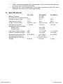
Solar Charge Controller Owner’s Manual SC 1210 SC 1210LD SC 1220LD 1. INTRODUCTION Thank you for purchasing the KISAE Solar Charge Controller. With our state of the art, easy to use design, this product will offer you a reliable service to convert your PV solar energy to charge you battery in an effective and efficient way. It also protects your battery from overcharge by the PV or over discharge (LD model only) through the DC load connected. 2. PRODUCT DESCRIPTION The KISAE Solar Charge Controller package includes the items list below. Solar Charger controller Owner’s manual 3. Important Safety Instructions This section contains important safety information. Before installing or using the unit, READ ALL instructions and cautionary markings on or provided. The unit contains no user-serviceable parts. See Warranty section for how to handle product issues. FIRE AND/OR CHEMICAL BURN HAZARD Do not cover or obstruct any air vent openings and/or install in a zero-clearance compartment. FAILURE TO FOLLOW THESE INSTRUCTIONS CAN RESULT IN DEATH OR SERIOUS INJURY When working with electrical equipment or lead acid batteries, have someone nearby in case of an emergency. Wear eye protection and gloves. Avoid touching your eyes while using this unit. Keep fresh water and soap on hand in the event battery acid comes in contact with eyes. If this occurs, cleanse right away with soap and water for a minimum of 15 minutes and seek medical attention. Batteries produce explosive gases. DO NOT smoke or have an open spark or fire near the system. Keep unit away from moist or damp areas. Avoid dropping any metal tool or object on the battery. Doing so could create a spark or short circuit which goes through the battery or another electrical tool that may create an explosion. WARNING: Explosion hazard! DO NOT use the unit in the vicinity of flammable fumes or gases (such as propane tanks or large engines). Prolonged contact to high heat or freezing temperatures will decrease the working life of the unit. Use only with 12 V battery and do not exceed the voltage and current ratings of the unit. Use only with PV array rated for 12V battery. Do not short circuit the PV array and or the load while connected to the unit. This will permentantly damage the unit. Protect the unit from direct sunlight. Unit should be properly grounded. Grounding should comply with local codes. Do not connect and disconnect the unit when the circuit is live. 4. Understanding the unit See Note: 1 2 To PV Panel 3 4 To Battery 5 6 7 To DC Load The first pair of screw terminals is the input terminal for solar panel connection. The second pair of screw terminals is the bi-directional terminal used for battery connection. This acts as an output terminal for battery charging from the PV panel through the unit and acts as an input terminal for battery discharging to DC load through the controller. The third pair of screw terminals is the output terminal for DC load connection. Note: Use the jumper provided to connect terminal 6 and 7 for sealed battery type. ‘Charging’ green indicator turns on when PV solar panel provides enough energy for battery charging. It turns off when sunlight is not available or insufficient to charge the battery. ‘Load Disconnect’ indicator (LD models only) turns on when battery charge is low and the Load Output is disconnected from the battery. The Load Output will automatically reconnect when the battery voltage is charged to above 12.6V. 5. Installation Instructions CAUTIONS: Please verify the rating of the PV panel size, battery voltage type and the total power consumption of the DC load before installing the unit. SC 1210 12V, 10 ADC SC 1210LD 12V, 10 ADC with load disconnected SC 1220LD 12V, 20 ADC with load disconnected Step 1: Select Battery type Factory default setting with jumper installed is for sealed battery type. For the use of flooded battery, remove the installed jumper. Step 2: Connecting a 12V battery Connect ‘-‘ terminal of Energy Storage (pin 4) on unit to 12V battery negative terminal Connect ‘+’ terminal of Energy Storage (pin 3) on unit to 12 V battery positive terminal Step 3: Connecting a PV panel Connect ‘-‘ terminal of Solar Input (pin 2) on unit to PV panel negative terminal Connect ‘+’ terminal of Solar Input (pin 1) on unit to PV panel positive terminal Step 4: Connecting a DC load Connect ‘-‘ terminal of Load Output (pin 6) on unit to PV panel negative terminal Connect ‘+’ terminal of Load Output (pin 5) on unit to PV panel positive terminal Note: Maximum wire size of AWG#10 can be used on the terminal and tighten the screws snugly. 6. Operation and Maintenance The unit is fully automatic and no unit setting is required once it is installed properly. It is recommended to verify the state of charge of the battery regularly and to verify that the load connected to the unit is not over rated for the unit. It is also recommended to verify that the power consumption on the load is less that the PV panel can produce. The following periodic inspections and maintenance tasks are highly recommended for best performance. Check for any rusting or corrosion around the battery terminals Verify the PV panels and loads connected do not exceed the unit rating Tighten all the 7 terminal screws and inspect for any loose, broken or burnt wire connections. Ensure PV panel is mounted properly and is placed in the right position. Check for any dirt, debris and corrosion on the panel. Periodically clean solar panels with water and do not use chemicals 7. Troubleshooting No Output: Check DC load terminal connection. Connection may be loose or disconnected. Check connection polarity. Reverse polarity on any terminals will damage unit and is not covered by warranty. Verify battery voltage is not too low. For LD model, check Load disconnect LED is ON. Verify battery voltage is above 12.6V. Battery did not charge: Verify the PV panel is functioning properly. Check for poor connection on the PV panel Verify PV panel is not blocked by any surrounding tall objects. Check the PV panel surrounding area. Check PV and battery connection. Loose connection will reduce unit performance. Check connection polarity. Reverse polarity on any terminals will damage unit and is not covered by warranty. Verify the DC load consumption. The power consumed by the DC load should be less than the PV panel generates. 8. Specifications SC 1210 SC1210LD Battery Voltage: 12 VDC PV open circuit voltage (max): 26 VDC Charge current (max): 10 A 10 A Load current (max): 10 A 10 A Surge Current (max) 35A for 1 min 35A for 1 min Operational current: < 10 mA <10 mA Regulated battery voltage Sealed type: 14.2 VDC Flooded type: 14.6 VDC Load disconnect voltage: N/A < 11.5 VDC Load re-connect voltage: N/A 12.6 VDC Recommended wire size: # 12 AWG # 12 AWG Operating temperature - 40 C to 60 C Dimensions (L x W x H) 4.1 x 4.1 x 1.3 in Weight: 0.28 kg 0.32 kg KISAE BATTERY SC1220LD 20 A 20 A 40A for 1 min <15 mA < 11.5 VDC 12.6 VDC # 10 AWG 0.35kg CAR BATTERIES