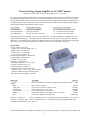
1
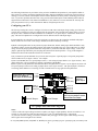
Universal Transconductance Amplifier
Universal Voltage Output Amplifier for LI-COR™ Sensors
(Amplifies LI-COR sensor current to voltage-logger level)
Revision D
User Manual
Contents:
Introduction ................................................................... 2
Configuring your UTA .................................................. 3
Connections ................................................................... 4
Calculations ................................................................... 5
Troubleshooting............................................................. 6
UTA Recalibration......................................................... 6
Physical Dimensions ..................................................... 8
UTA Circuit Schematic ................................................. 9
rev. D ©2004 EME Systems, 2229 Fifth St., Berkeley CA 94710; (510) 848-5725; fax: (510) 848-5748; www.emesys.com
Universal Voltage Output Amplifier for LI-COR™ Sensors
(Amplifies LI-COR sensor current to voltage-logger level)
Revision D
The UTA is a special purpose amplifier that converts the microamp-level current output of LI-COR1 light sensors to
a corresponding signal voltage. The UTA can be configured at EME Systems or by the end user for any one of the
three standard LI-COR sensors, and for any one of four popular output voltage ranges, through the manipulation of
two plug-in jumpers. The UTA provides a simple interface between LI-COR sensors and voltage input data loggers,
chart recorders, HVAC, and greenhouse control systems.
LI-COR sensor
LI-190 PAR sensor
LI-200 Pyranometer
LI-210 Photometer
Typical full sun response
12-15µA @ 2000 µE/m2s
100µA @ 1000 W/m2
40µA @ 100 klux (=9290 ftcd)
UTA output ( user selectable )2
1, 2, 5, 10 Volts out @ 16.67µA input
1, 2, 5, 10 Volts out @ 125µA input
1, 2, 5, 10 Volts out @ 50µA input
Alternate gain settings are available on special order. In particular, a special UTA/HOBO is available for use with
ONSET HOBO3 data loggers. Also, higher gains are available for use of the sensors at low light levels, indoors or
underwater. The calibration tag provided by LI-COR with each sensor, in conjunction with the preset amplifier gain
factor can be used to compute the light levels incident on the sensor with a high degree of accuracy.
Specifications:
• Supply Voltage: 5–24 VDC
(supply volts > full scale output volts + 2)
• Supply Current: less than 1mA
• Gain accuracy:± 0.5% all ranges
± 0.2% on factory preset range
•Voltage output in darkness: <4 millivolts
• Supply Voltage variation effect:
less than 0.01% per Volt
• Response: 2 milliseconds
• Operating Temperature: -30°C to +70°C
• Tempco: less than 0.01% per °C
• Output impedance: 1000Ω ±1%
• NEMA 4 gasketed white polycarbonate
enclosure: 1.37“ x 1.96” x 2.55“ (4.15” w/glands)
gland nut or BNC at input, gland nut at output
Phoenix® beryllium/copper i/o terminals.
description
price ea.
Order item
UTA........................................... base price, standard UTA with i/o cord grips, polycarbonate enclosure $105
Options:
/BNC ......................................... BNC connector on input
add $10
/input preset............................... preset input for LI-190, LI-200 or LI-210
no charge
/output preset............................. preset output for 1, 2 5 or 10 volts
no charge
/special output ........................... preset output range for special value
add $15
/HOBO ...................................... special to run from 2.5 volts supply, 0-2.5 volt fs output
add $10
/NE ............................................ no enclosure; amplifier electronics only
subtract $15
Example 1: UTA/200/5
UTA pre-configured for 0 to 5 volt output from LI-200 Pyranometer - price: $105 ea
Example 2: UTA/BNC/190/1 UTA pre-configured for 0 to 1 volt output from an LI-190 Quantum PAR sensor
with BNC input termination - price: $115 ea.
rev. D ©2004 EME Systems, 2229 Fifth St., Berkeley CA 94710; (510) 848-5725; fax: (510) 848-5748; www.emesys.com
1
The following instructions are provided to assist you in the installation and operation of your amplifier. While we
have made every effort to protect the amplifier from faults, improper installation or misuse may result in incorrect
readings, or at worst, failure of the amplifier. Please read the manual in its entirety before connecting power to the
UTA. If you have questions about the UTA or any portion of this manual please contact EME Systems technical
support between the hours of 9:00 AM to 5:00 PM PST at: (510) 848-5725, or (510) 848-5748 fax. You may also
post your questions to us by e-mail on Internet at address: [email protected]
Configuring your UTA:
The first step in using the UTA is to configure it for the LI-COR sensor and output voltage scaling you wish to use.
You may have ordered your UTA pre-configured for the appropriate sensor and full scale output voltage you need.
The preset value is marked on a label outside the UTA enclosure. If so, please skip to “connections” on the next
page. This section explains how to configure the UTA for different sensors and output ranges.
1) UTA amplifiers are enclosed in a protective enclosure. To gain access to the connection terminals and jumper
blocks, remove the two corner screws using a standard screwdriver and lift up on the top.
2) Refer to the diagram below for the position of jumper blocks JP1 and JP2. Each jumper block should have only
one jumper in place. Choose the jumper position on JP1 that corresponds to the type of LI-COR sensor you will be
using. Choose the jumper position on JP2 that corresponds to your desired full scale output voltage. To move the
jumpers, pull them up and off the posts, and plug them back into the desired position. A copy of this diagram is
attached on a label on the inside the lid of the UTA enclosure.
3) If you ordered a special calibration for your UTA, then it may have a special jumper. The special jumper has a
resistor soldered to it (see figure 2 below). For example:
a) For a UTA/HOBO, there is a special jumper on the 1 V F.S. setting of jumper block 2 (see figure 2 below). This
jumper allows the UTA to reach the 2.5 Volt F.S. requirement of the HOBO.
b) For a special LI-210 photometer calibration that allows the photometer to register very low light levels, there will
be a special jumper on the LI-190 setting of jumper block 1 (See figure 2 below). The special jumper is on this LI190 setting, rather than the LI-210 setting, in order to maximize the 1st stage gain from the photometer.
Jumper Block JP1, 3 position
Use only one jumper to
select proper LI-COR sensor
Li-Cor
Sensor
Input
LI-190
LI-200
LI-210
Gnd
Signal Out
Vcc
(5-24 VDC)
Shield or
Bare Wire
Power supply
input and
signal output
1.0 V F.S.
2.0 V F.S.
5.0 V F.S.
10.0 V F.S.
Clear wire
Jumper Block JP2, 4 position
Use only one jumper to select
desired full scale output.
Normal Jumper
Special Jumper
UTA jumper and connections diagram
Notes:
• Choose a full scale output voltage less than or equal to your logger’s input capability -but not too much less. For
example, if your logger has a full scale input range of 2.5 volts, you should choose the 2 volt position.
• If you select too low a setting, you will lose resolution and your logger will not register subtle changes and may
fail to register the lowest light levels of interest.
rev. D ©2004 EME Systems, 2229 Fifth St., Berkeley CA 94710; (510) 848-5725; fax: (510) 848-5748; www.emesys.com
2
• If you select too high a setting, the amplifier may overdrive or saturate the input circuit on your meter or even
damage its inputs. The highest light levels will all register as one value: off scale!
• You may wish to purposely select a higher output setting to achieve greater sensitivity at low light levels. This
might be useful in studies of indoor lighting where full-sun intensities will never be attained.
• The UTA power supply must always be greater than or equal to the full scale output voltage.
• Use alcohol to rub off the old mark on the calibration label, and a Sharpie™ marker for the new one.
Connections:
1) UTA amplifiers are enclosed in a protective cabinet. To gain access to the connection terminals and jumper blocks,
remove the two corner screws using a standard screwdriver and lift up on the top.
2) Refer to figure 2. The UTA has connections for the LI-COR sensor input at one end of the circuit board and for
the power supply and signal output at the other end. The input connections may be either a pair of black and white
color coded screw terminals or a BNC connector. The UTA power supply and output signal is always terminated
with a strip of three screw terminals, color-coded red, green and black.
a) LIXXX-SZ (bare wire termination ): LI-COR part numbers ending with “SZ” are terminated with a stripped and
tinned bare coaxial cable. These sensors should be used with a standard UTA amplifier. Connect the inner conductor
( green, white, or clear ) to the white colored terminal on the UTA board and connect the outer wire (shield or tinned
copper wire) to the neighboring black terminal.
or
LIXXX-SA (BNC termination): LI-COR part numbers ending with a “SA” are terminated with a BNC connector
and should be used with the UTA-BNC amplifier. Simply align the connector with its mate on the outside of the
UTA-BNC and twist the two halves together. The BNC connectors should lock together when they are properly
seated.
b) Connect the power supply from your data logger between the black (common) and red (+ DC voltage) terminals
on the opposite end of the circuit board. The power supply voltage must be at least 5 volts, and must be greater than
or equal to the full-scale output voltage you select for the UTA (ie, if using the 10.0 V F.S setting, your power supply must
provide at least 12 volts, or it must provide 7 volts power for 5 volt output, or 5 volts power for a 1
or 2 volt output. The UTA draws less than 1mA of current, making a battery a viable option for a power supply.
c) The signal from the UTA should be taken between the green and black terminals. Green is signal and black is
common (ground). The green terminal should be connected to the signal input of your logger and the black terminal
should be
connected to the power supply ground. Note that the black terminal is common to both the power
supply and signal line.
3) Check all connections for proper polarity and be sure all wires are clamped solidly in place. Replace the top cover
on the enclosure and tighten the corner screws. Take care not to over tighten the cover screws as this may cause the
cover to deform or “saddle” which can compromise the seal.
Note:
Noise sources: For long runs in the presence of halide lamps or other noise sources, you should consider using
shielded, three-wire cable for the power and signal connections between the logger and the UTA, with the shield tied
to common at one end only.
Long wire runs: The LI-COR sensors come with 10 feet or 50 feet of cable. The rest of the wire run from the UTA
to the data logger or controller should be made with #22 gage or heavier wire. The current flowing in the ground
lead creates an error voltage that is added to the apparent output signal. For example, 1000 feet of 22 gage wire
has a resistance of approximately 15 ohms. The UTA power supply current of 0.0005 amp flowing in that wire
would create a 7.5 millivolt offset. On the 5 volt scale, the error would be 0.0075/5 * 100 = 0.15%. It is unlikely
that you will be using such long wire runs. However, poor connections in the ground lead can provoke similar errors.
Be sure the ground lead is well secured. The UCLC amplifier is better suited to transmission of data as a current
over long distances.
rev. D ©2004 EME Systems, 2229 Fifth St., Berkeley CA 94710; (510) 848-5725; fax: (510) 848-5748; www.emesys.com
3
Calculations:
In order to convert the UTA’s output voltage into the appropriate units of light, you will have to program your equipment to multiply the UTA output voltage times the multiplier printed on the calibration tag that accompanies each
individual LI-COR sensor, multiplied by the UTA‘s transconductance gain (µAmp per Volt). Refer to the calibration tag on your LI-COR sensor for the multiplier for your particular LI-COR sensor. Drop the minus sign from the
multiplier. This is your sensor conversion factor.
Light Level = (UTA output)*(sensor conversion factor)*(UTA transconductance gain)
Please refer to the table below to find the UTA transconductance gain corresponding to their positions.
Table of LI-COR sensor types Vs. Transconductance gain for various jumper settings
Rev. D
JP2-1) 1 Volt fs
JP2-2) 2 Volts fs
JP2-3) 5 Volts fs
JP2-4) 10 Volts fs
JP1-1) LI-190
16.67 µA/V
8.33 µA/V
3.33 µA/V
1.667 µA/V
JP1-2) LI-200
125 µA/V
62.5 µA/V
25 µA/V
12.5 µA/V
JP1-3) LI-210
50 µA/V
25 µA/V
10 µA/V
5 µA/V
Example calculations:
Example 1: Suppose you will be using your UTA in conjunction with a Quantum PAR sensor (LI-190) , and that
the Quantum sensor calibration tag states a multiplier of -148.5µE/m2s per µA. Suppose your data logger has a full
scale input of 1.28 volts. You choose the 1.0 volt output setting for your UTA, with a transconductance gain of 16.67
µA/V (1st column, 1st row in the table). The conversion is:
light level in µE/m2s = (UTA volts) * (148.5 *16.67) = (UTA volts) * (2475.5 µE/m2s per volt)
A 0.836 volt output signal would indicate 2069.5 µE/m2s.
Example 2: Suppose you will be using your UTA in conjunction with a Pyranometer sensor (LI-200), and that the
Pyranometer sensor calibration tag states a multiplier of -9.8 W/m2 per µA. Suppose your meter has a full scale
input of 5.0 volts You choose the 5.0 volt output setting for your UTA, with a transconductance gain of 25 µA/V
(3rd column, 2nd row in table). The conversion is:
light level in W/m2 = (UTA volts) * (9.8 *25) = (UTA volts) * (245 W/m2 per volt)
A 4.6 volt output signal would indicate 1127 W/m2
Example 3: Suppose you will be using your UTA in conjunction with a Photometer sensor (LI-210), and that the
Photometer calibration tag states a multiplier of -2.63 klux/µA. Suppose your recorder has a full scale input of 2.5
volts. You choose the 2.0 volt output setting for your UTA, with a transconductance gain of 25 µA/V ( 2nd column,
3rd row in table). The conversion is:
light level in klux = (UTA volts) * (2.63 *25) = (UTA volts) * (65.75 klux per volt)
A 1.25 volt output signal would indicate 82.2 klux. If you need units in footcandles, 1 footcandle=10.764 lux.
Notes:
1) If you need more sensitivity at low light levels, choose a higher UTA transconductance gain, or contact EME
Systems for a special calibration.
2) If you ordered a UTA/HOBO, please refer to the document “Additional Documentation for the UTA/HOBO”
for calculations and other information. This document is also available online as a PDF at
http://www.emesystems.com/uta_hobo_dat.htm.
rev. D ©2004 EME Systems, 2229 Fifth St., Berkeley CA 94710; (510) 848-5725; fax: (510) 848-5748; www.emesys.com
4
Troubleshooting:
1) UTA appears to be dead; the output voltage is stuck at zero or full scale regardless of light level:
Things to check:
1a) Check supply voltage and polarity at the red and black terminals of the UTA circuit board.
1b) Check the sensor polarity, make sure that the center conductor on the sensor wire is connected to the white terminal and the outer shield wire is connected to the black terminal on the UTA input.
1c) Check the screw terminal connections, make sure all of the wires are clamped solidly in place. The sensor wire
should be clamped in the terminal, not loose underneath it. The center conductor of the sensor wire is delicate; be
sure it is not broken.
1d) If you are testing the unit on a bench indoors you may have to move it very close to an artificial light source to
get a response. Light levels indoors are much, much weaker than sunlight. Be sure the protective red cap is
removed from the sensor.
1e) Check if the sensor and gain selecting jumpers are in place, oriented properly and seated firmly.
1f) Has there been a lightning strike in close proximity? Although the UTA is protected against excess or reversed
power supply voltages, it can not be expected to survive catastrophic extremes.
1g) Check for evidence of water entry into the cabinet. In regions of extreme humidity or precipitation it may be
wise to place a dessicant, such as silica gel, inside the UTA’s cabinet.
2) Amplifier seems to be responding to light, but the output seems too low or too high:
Things to check:
2a) Check the position of the jumpers on JP1 and on JP2 against the diagram attached to the inside of the lid of the
enclosure and the calibration label. Is the setting correct?
2b) Be sure you are using the correct multiplier in your calculations. Refer to the table on the previous page and the
jumper positions in the box. The version number should be printed on the top label or on the calibration label.
2c) Place sensor in full unobstructed sunlight, you should see a significant increase in output voltage. Indoor lighting is much, much weaker than full sunlight. The standard amplification factors are designed to accommodate full
tropical sunlight conditions. If you will be using your sensor in generally low-light conditions, say indoors or in the
arctic or under a plant canopy, you may wish to select a higher output voltage setting to bring the signal into the
dynamic range of your data logger. Please consult the LI-COR literature and references, or contact EME Systems
for assistance.
2d) The power supply must be at least 2 volts greater than the desired full scale output voltage (except the
UTA/HOBO version, which operates rail to rail).
3) The amplifier output is unstable and readings fluctuate too much under constant lighting conditions:
Things to check:
3a) Check all of the connections to the screw terminals. Make sure all connections are tight and secure.
3b) Check for an AC component in the power supply voltage. The power supply should be filtered direct current
and should stay at least 2 volts above the full scale output voltage.
3c) Is the sensor is close to a strong electromagnetic field, such as a halide lamp or a refrigerator motor or other AC
power equipment? If so, try to reroute the sensor cable, or run the sensor cable inside a grounded metal conduit.
Avoid running the sensor cable in the same conduit as AC power lines.
3d) Occasionally, oscillations can arise due to reactive loading on the signal cable. Placing a 0.1µF capacitor
between the signal terminal and the common terminal at your data logger input will usually suppress the oscillation.
UTA re-calibration:
The jumpers in the UTA select certain popular values for the transconductance gain. If you want to set an intermediate value of gain, it is possible to do so. The diagram below shows the location of the gain adjustment trimmer. Use
a precision current sink as the input signal for the amplifier and an accurate (4digit) DVM to read the amplifier output voltage. Set the output of the precision current sink to the desired the full scale sink current. Adjust the first
stage gain trimmer to give the corresponding full scale output. For example, to calibrate for a Quantum PAR sensor,
we standardize with a 16.0 microamp input current, and a 5.0 volt output voltage. The adjustment range is ± 20% of
the fixed gain value.
rev. D ©2004 EME Systems, 2229 Fifth St., Berkeley CA 94710; (510) 848-5725; fax: (510) 848-5748; www.emesys.com
5
UTA Circuit board
Precision (4 digit ) DVM
4.0000
Vin
Precision Floating
Current Source
Gnd
160.00
Isink
Gnd
Regulated DC power supply
Vou
t
Gnd
First stage gain
trimmer adjustment
Notes:
• Each LICOR sensor has an individual calibration tag. The standard calibration of the UTA requires that the calibration constant be entered in software. Alternatively, a UTA can be calibrated to match an individual LI-COR sensor,
so that, say, 1000 watts/meter2 input will give 4.00 volts output. That UTA then stays with that particular LICOR
sensor. In effect the calibration is done in the hardware, rather than in the software. The advantage is that it simplifies the software, particularly where a low-resolution converter will be used, or where calibration constants can not
be entered in software, or where several light sensors must be interchangeable without reprogramming. The disadvantage is that if the LICOR sensor needs to be replaced or recalibrated, then so must its attached UTA.
For example, suppose you have a Quantum PAR sensor (LI-190), and that its calibration tag states a multiplier of 187.5 µE/m2s per µA. Suppose you want to calibrate the UTA to have an output of exactly 4.0 volts when the solar
input is 2000 µE/m2s. Note that the sensor output when the solar radiation is 2000µE/m2s will be 10.667
microamps (=2000/187.5). One way to do the calibration would be to apply a current of exactly 10.6667
microamps to the UTA input and then adjust the trimmer in the UTA to give an output of 4.0 volts. It may be more
convenient to use a standard current sink, say 10 microamps, and then set the output to 3.750 volts. (=4*10/10.667).
It may be necessary to add an extra resistor to the jumper block in order to achieve calibrations that are far from the
center values. Please contact EME Systems for assistance.
Alternatively, a calibrated light source such as LI-COR’s 1800-02 Optical Radiation Calibrator can be used to match
a LI190 and LI210 sensor to the UTA. Place the sensor in the calibrator and adjust the first stage gain trimmer to
match the desired voltage output. Or, you can use one recently calibrated LI-1xx as your standard for calibrating
others of the same type, given a stable light source.
• LI-COR recommends that all LI-XXX series sensors be returned for re-calibration every two years. This will
ensure proper calibration and compensate for the effects of aging and degradation on the sensor.
rev. D ©2004 EME Systems, 2229 Fifth St., Berkeley CA 94710; (510) 848-5725; fax: (510) 848-5748; www.emesys.com
6
UTA, Polycarbonate Enclosure, Physical Dimensions:
UTA
(standard)
UTA-BNC
1.95"
2.55"
4.075
2.55"
4.15"
1.40"
0.55
0.55"
1.95"
1.95"
2.10"
2) Holes 0.175" ID
Screws Supplied
Mounting Template
(not to scale)
1.50"
rev. D ©2004 EME Systems, 2229 Fifth St., Berkeley CA 94710; (510) 848-5725; fax: (510) 848-5748; www.emesys.com
7
UTA Schematic:
The information contained herein is provided as an aid to resolving questions about the amplifier and its
application. It is not meant for general distribution and remains the exclusive property of EME Systems.
Sensor
Li 190
Li 200
Li 210
J5
R4, 66.5KΩ
J2
0.1%
R12, 11.3KΩ
R3, 8.87KΩ 0.1%
J3
R2, 22.1KΩ 0.1%
J4
R11, 45.3KΩ
R10, 102KΩ
C1, 0.001µF
Gain
1X
0.1%
J6
2X
0.1%
J7
5X
0.1%
J8
10X
C2, 0.001µF
R1, 100Ω
White
inner
U1=LT1078IN
2 1
U1a
3 +
Li-Cor Sensor
Li 190
Li 200
Li 210
D1
4.7v
1N5230
R6
30.1KΩ
D2, SD103
Gain RT1
Trim 2KΩ
6
1.0 V
-
8
7
U1b
5
+
R7, 1KΩ
Signal
GREEN
4
R13
R8, 14.7k
BLACK
Shield
Power
+5 to +18
RED
1.064 V
R9
11.3KΩ
0.1%
not used
pulldown
UTA — Universal Transconductance Amplifier
• Rev B changed LI190 fs to 16µA
• Rev C changes first stage gain for 16µA, 120µA & 48µA fs
• Rev D changes first stage gain for 16.67µA, 125µA and 50µA fs
• can use LTC1047 for highest accuracy.
• Special for HOBO, short D1, U1=LT1490A, gain 2.5(16.9 KΩ at jumper 5)
C4, 0.1
C3, 0.1µF
Common
BLACK
Rev C UTA 10/2002
EME Systems
2229 Fifth St.
Berkeley CA 94710
tel: (510) 848-5725
fax: (510) 848-5748
[email protected]
1 LI-190,LI-200,LI-210 and part designations are trademarks and the exclusive property of LI-COR Lincoln,
Nebraska
2 In revision C, the full scale for PAR was changed to 16 µamps, (previously 12.5 µamps) to allow for
higher LI190 outputs, full scale
for pyranometer was changed to 120 µA, and photometer was changed to 48 µA full scale. Rev. C is
indicated on the top label of the
UTA enclosure.
3 HOBO is a trademark of ONSET Computer Corporation, Bourne, MA., U.S.A. (www.onsetcomp.com)
rev. D ©2004 EME Systems, 2229 Fifth St., Berkeley CA 94710; (510) 848-5725; fax: (510) 848-5748; www.emesys.com
8