1
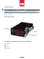
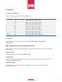
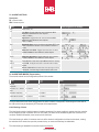
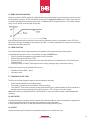
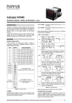
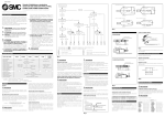
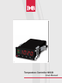
Temperature Controller N1020
User Manual
B+B Thermo-Technik GmbH
Heinrich-Hertz-Straße 4
D-78166 Donaueschingen
Fon +49 771 83160
Fax +49 771 831650
E-Mail: [email protected]
02
www.bubthermo.de
Foreword
Dear customer,
We thank you for having purchased the Controller N322 and we are very glad that you decided to buy a product of
B+B Thermo-Technik GmbH. We hope this product will fully satisfy you and will assist you effectively in your work.
This Device has been developed to be technically highly up-to-date and has been designed in accordance with the prevailing European and German national directives and rules. For a proper and effective usage of the product the customer
shall observe the following Operating Instructions. In the case that against one’s expectations any trouble occurs which
you can not resolve yourself, please contact our service centers or our authorized dealer. We will provide you rapid and
competent help to minimize the risk of long time outfalls.
The following operating Instruction is an indispensable part of this Product. It contains important advices for the starting
up and further use of the device.
General Informations
This Operation Manual is intended to serve as an aid in the proper setup, installation and operating of the B+B product.
All essential details of the equipment and all actions required on the part are clearly presented and explained. We thus
ask that you read this manual carefully before proceeding to work with the equipment. Keep this manual available for
ready reference in a convenient and conspicuous location near the equipment.
www.bubthermo.de
03
Content
Foreword03
General Informations
Symbols Employed
05
Warning Signs
Safety Instruction’s
06
Intendend Use
07
Disposal
1. Product Description
08
2. Scope of Delivery
09
3. Device Name
3.1. Description of the buttons on the front of the Indicator
4. Installation / Connections
10
5. Features 11
5.1. Input Type Selection
5.2. Outputs
5.3. Table Alarm Function 12
6. Operation 14
6.1. Display 6.2. Operation
13
7. Description of the Parameters
17
8. Configuration Protection
19
9. Determination of PID - Parameters
20
10. Maintenance
22
7.1. Operating Level 7.2. Tuning Level
7.3. Alarm Level16
7.4. Configuration Level
17
7.5. Calibration Level18
8.1. Access Password 8.2. Protection Access Password
8.3. Master Password
8.1. Access Password 8.2. Protection Access Password
10.1. Problems with the controller 10.2. Calibration of the input
11. N1020 Parmeter Table23
12. Technical datas24
13. Order Informations25
04
www.bubthermo.de
Symbols Employed
Sign
Meaning
Notice
Advice
It is necessary to read the following advices before using the product.
The used symbols in the manual acts first of all as eye catcher for
security risks. The symbols do not replace the security advices. The
text must be read completely.
Necessarily to observe
This symbol designates important advices and tips which are necessary for the success of a procedure. They have to be followed in order
to get good results.
Warning Signs
Warning Signs
Meaning
This symbol advises the user of danger for persons, material or environment. The text gives information
that must be necessarily followed to avoid any risks
Caution against hot surfaces (BGV A8, GUV-V A8/W26) and hot liquids or substances
Caution against liquids and hot substances
Caution against dangerous explosive substances (BGV A8, GUV-V A8/W02)
Caution against moving maschines (W29)
Caution against moving parts
Caution against electromagnetic fields (BGV A8, GUV-V A8/W12)
Caution against severe cold (BGV A8, GUV-V A8/W17)
Caution against dangerous high electrical voltage (BGV A8, GUV-V A8/W08)
Caution against dangerous explosive atmosphere (BGV A8, GUV-V A8/W21)
Electronic waste
www.bubthermo.de
05
Safety Instructions
For damages caused by failure to observe these safety and operating instructions, B+B Thermo-Technik GmbH assumes
no liability for damages.
This device has been designed and tested in accordance to the safety regulations for electronic devices.
However, its trouble-free operation and reliability cannot be guaranteed unless the standard safety measures and special
safety advises given in this manual will be observed when using it.
Trouble-free operation and reliability of the device can only be guaranteed if it is not subjected to any climatic conditions
than those stated under “Specifications”.
If the device is transported from a cold to a warm environment condensation may result in a failure of the function. In
such a case make sure the device temperature has adjusted to the ambient temperature before trying a new start-up.
If device is to be connected to other devices the circuitry has to be designed most carefully. Internal connection in third
party devices (e.g. connection GND and earth) may result in not-permissible voltages impairing or destroying the device
or another device connected.
Warning:
Only devices with mains input: If the device is operated with a defective mains power supply (e.g. short circuit from mains
voltage to output voltage) this may result in hazardous voltages at the device (e.g. at sensor socket)
If there is a risk whatsover involved in running it, the device has to be switched off immediately and to be labeled accordingly to avoid re-starting. Operator safety may be at risk if:
●● There is visible damage to the device
●● The device is not working as specified
●● The device has been stored under unsuitable conditions for a longer time
In case of doubt, please return device to manufacturer for repair or maintenance.
Caution:
Do not use these product as safety or emergency stop devices, or in any other application where failure of the product
could result in personal injury or material damage. Failure to comply with these instructions could result in death or serious injury and material damage.
06
www.bubthermo.de
Intended Use
The use of the unit in fields other than those indicated under “SAFETY INSTRUCTIONS” is not allowed for
safety reasons.
This instruction manual does not at all substitute any additional instruction manuals of connected accessories!
Disposal
This unit has been marked in accordance with the European Device 2002/96/EC on waste electrical and electronic
equipment (WEEE).
At the end of its useful operating life, dispose of the unit as electrical scrap.
Please ask either B+B Thermo-Technik GmbH or your specialist dealer for information on your local collection point.
Within the scope of application if this Directive, B+B Thermo-Technik GmbH is responsible for proper disposal of this
unit.
www.bubthermo.de
07
1. Product Description
The Controller N1020 is a small and yet powerful temperature controller. It accepts most of the temperature sensors
used in industry and its 2 outputs can be configured independently as control or alarm output. It also embeds an
auto-adaptative PID control algorithm for best system performance. The configuration of the input and output types, the
alarms and other functions, are all accessed and programmed via frontal keyboard. It is important that the users read
carefully this manual before using the controller. Verify if the release of this manual matches the instrument version (the
firmware version is shown when the controller is energized). The Controller N1020 main characteristics are:
•
•
•
•
•
•
•
•
•
•
•
08
Sensor universal input
Self-tuning PID parameters
2 outputs: 1 relay and 1 logical pulse for SSR; Output functions: Control, Alarm1 and Alarm 2
8 distinct alarm functions
Programmable timer
Function key for enabling/disabling outputs, resetting the timer or turning the timer ON/OFF
Programmable soft-start
Rampe function
Password for parameters protection
Capability of restoring factory calibration
Universal power supply
www.bubthermo.de
2. Scope of Delivery
Article Name
Article Number
Description
Temperature Controller N1020
0556 0111
1 x Controller N1020, 1 x User manual on CD
An identification label is on the side of the controller with wiring instructions. Check if the features described are in
accordance with your order.
3. Device Description
Messages
Display
Programming keys
3.1. Description of the buttons on the front of the Indicator
Program-key
Up-key
Down-key
Function-key
www.bubthermo.de
09
4. Installation / Connection
The controller must be fastened on a panel, following the sequence of steps described below:
•
•
•
•
Prepare a panel cut-out 23 x 46 mm
Remove the mounting clamps from the controller
Insert the controller into the panel cut-out
Slide the mounting clamp from the rear to a firm grip at the panel
4.1. RECOMMENDATIONS FOR THE INSTALLATION
•
•
•
•
•
All electrical connections are made to the screw terminals at the rear panel of the controller. They accept wire sizes
from 0.5 to 1.5 mm2 (16 to 22 AWG). The terminals should be tightened to a torque of 0.4 Nm (3.5 lb in).
To minimize the pick-up of electrical noise, the low voltage DC connections and the sensor input wiring should be
routed away from high-current power conductors. If this is impractical, use shielded cables. In general, keep cable
lengths to a minimum.
All electronic instruments must be powered by a clean mains supply, proper for instrumentation.
It is strongly recommended to apply RC‘S FILTERS (noise suppressor) to contactor coils, solenoids, etc.
In any application it is essential to consider what can happen when any part of the system fails. The controller features by themselves can not assure total protection.
4.2. ELECTRICAL CONNECTIONS
The controller complete set of features is drawn in the Figure below. The features loaded in a particular unit are shown
on its label:
10
www.bubthermo.de
5. Features
5.1. INPUT TYPE SELECTION
Select the input type (in parameter type) from Table below:
TYPE
CODE
RANGE OF MEASUREMENT
J
tcJ
Range: -110 to +950°C (-166 to +1742°F)
K
tcK
Range: -150 to +1370°C (-238 to +2498°F)
T
tcT
Range: -160 to +400°C (-256 to +752°F)
N
tcN
Range: -270 to +1300°C (-454 to +2372°F)
R
tcR
Range: -50 to +1760°C (-58 to +3200°F)
S
tcS
Range: -50 to +1760°C (-58 to +3200°F)
B
tcB
Range: +400 to +1800°C (+752 to +3272°F)
E
tcE
Range: -90 to +730°C (-130 to +1346°F)
Pt100
Pt
Range: -200 to +850°C (-328 to +1562°F)
0 to 50 mV
LO.50
Linear programmable indication -1999 to 9999
5.2. OUTPUTS
The N1020 offers two output channels, user configurable as Control output, Alarm 1 output or
Alarm 2 output:
OUT1 - Logical pulse, 5 V DC / 20 mA, available at terminals 4 and 5
OUT2 - Relay SPST-NA, 3 A / 250 V AC, available at terminals 6 and 7
Note: The outputs can be configured independently from each other, for example, both can be control outputs at
the same time.
CONTROL OUTPUT
The control strategy can be configured as ON / OFF or PID.
ALARM OUTPUT
There are two alarms available in the N1020. The alarms can be assigned to either output, logical or relay. The
alarm functions are described below.
ALARM FUNCTIONS
The alarms can be configured to operate with nine different functions, as shown in the following table:
(Please see page 12)
www.bubthermo.de
11
5.3. ALARM FUNCTIONS
Description:
PV = process value
SPA = Alarm set point
Alarm
Function
Grafic (using Alarm 1 as example)
Off
Alarm turned off
Lo
Low Alarm: Triggers when the value of measured PV is
below the value defined for alarm setpoint.
(SPA 1 or SPA 2)
Hi
High Alarm: Triggers when the value of measured PV is
above the value defined for alarm setpoint.
(SPA 1 or SPA 2)
dIF
Bandwidth Alarm: In this function the parameters SPA1 and
SPA2 represent the deviation of PV in relation to the SP of
control
dIFL
Differential Low Alarm: Triggers when the value of measured PV is below the value defined for alarm setpoint.
dIFH
Differential High Alarm: Triggers when the value of measured PV is above the value defined for alarm setpoint.
t.On
Timer ON alarm. Sets alarm output ON when timer is running
t.End
Timer END. Configures the alarm to actuate when the timer
expires
IErr
Sensor break alarm: Activated when the input signal of PV is
interrupted, out of the range or when Pt100 in short-circuit
5.4. ALARM TIMER MODES (Temporization)
The controller alarms can be configured to perform 4 timer modes:
Mode
A1t1
A2t1
A1t2
A2t2
Action
Normal
Operation
0
0
Activation for a defined
time
1 to 6500 s
0
Activation with delay
0
1 to 6500 s
Intermittent Activation
1 to 6500 s
1 to 6500 s
The signs associated to the alarms will light when the alarm condition is recognized, not following the actual state of
the output, which may be temporarily OFF because of the temporization.
Initial Blocking of Alarm
The initial blocking option inhibits the alarm from being recognized if an alarm condition is present when the controller
is first energized (or after a transition from run YES to NO). The alarm will be enabled only after the occurrence of a
non alarm condition followed by a new occurrence for the alarm.
The initial blocking is useful, for instance, when one of the alarms is configured as a minimum value alarm, causing
the activation of the alarm soon upon the process start-up, an occurrence that may be undesirable.
The initial blocking is disabled for the sensor break alarm function.
12
www.bubthermo.de
5.5. RAMP AND SOAK FUNCTION
When the parameter Rate is configured, the N1020 performs a gradual Setpoint increase from the current PV value to
the temperature value set in SP The user defines the rate of rise in degrees per minute at the Rate prompt. When SP
is reached, the temperature is leveled at this point for 1 to 9999 minutes as programmed in the time prompt. Setting 0
(zero) at time defines an infinite length soak profile.
If set the Ramp function will work whenever the controller is powered on and the RUN parameter is set to YES or the
SP variable is changed. To disable the ramp function, set Rate = 0.0. After a power failure the controller will resume ramp
generation at the current value of PV.
5.6. TIMER FUNCTION
The N1020 embeds a timer function (decreasing) for applications that require particular process duration.
Once defined the time interval in the Time parameter, the timer will START when:
• When PV reaches the temperature programmed in the SP parameter
• When enabling the control (RUN = YES)
• By pressing the F-key when configured to Timer reset mode (the timer is reloaded with the Time parameter and
restarts counting)
• Pressing the F-key in ON/OFF mode stops the timer counting, pressing it again, resumes the counting
When the timer expires, the two possible actions can be:
•
•
Disables the control (RUN→ NO) or
Activate the alarm
5.7. FUNCTION FOR THE F-KEY
The F-key on the frontal keypad is meant for special commands, as follows:
•
•
•
Enable outputs (identically to the RUN parameter)
Timer reset: - reloads the timer and initiates a new time counting
Timer ON/OFF. Timer holds or resumes counting each time the F-key is pressed. Keeping the F-key pressed for 3
seconds resets the timer (reloads the timer to the value set in Time), initiating a new time counting
Note: when the F-key is configured as RUN = YES/NO (RUN = f-key), the controller outputs are both disabled after
powers up.
5.8. SOFT-START
The Soft-start function is generally used in processes that require slow start-up, where the instantaneous application of
100% of the available power to the load may cause damages to parts of the system.
In order to disable this function, the soft-start parameter must be configured with 0 (zero).
5.9. OFFSET
Allows fine trimming the PV indication to compensate for sensor errors. Default value: zero.
www.bubthermo.de
13
6. Operation
The controller´s front panel with its parts can be seen in figure below:
6.1. TOOLS
Display: Displays the current value of PV. When configuring a parameter, the display alternates between the parameter
prompt and its value (the parameter value is shown with a light blinking to differentiate it from the parameter prompt).
The display contains also the signs AT, OUT, RUN ALM and COM:
•
•
•
•
•
AT Indicator (AT): Stays ON while the controller is in tuning process.
OUT Indicator (Out): For relay or pulse control output; it reflects the actual state of the output.
RUN Indicator (RUN): Indicates that the controller is active, with the control output and alarms enabled (RUN=YES).
ALM Indicator (ALM): Signalize the occurrence of alarm condition. It lights when either alarm is active.
COM Indicator (COM): Flashes when there is RS485 activity.
P-Key: Used to walk through the menu parameters.
Increment key and
Decrement key: allows altering the values of the parameters.
F-Key: accesses special functions: RUN (toggles YES/NO) and the two modes of timer control.
6.2. OPERATION
When the controller is powered up, it displays its firmware version for 3 seconds, after which the controller starts normal
operation. The value of PV is then displayed and the outputs are enabled.
In order for the controller to operate properly in a process, its parameters need to be configured first, such that it can
perform accordingly to the system requirements. The user must be aware of the importance of each parameter and for
each one determine a valid condition.
The parameters are grouped in levels according to their functionality and operation easiness. The 5 levels of parameters are:
1 – Operation
2 – Tuning
3 – Alarms
4 – Configuration
5 – Calibration
The P-Key is used for accessing the parameters within a level.
Keeping the P-Key pressed, at every 2 seconds the controller jumps to the next level of parameters, showing the first
parameter of each level:
PV >> atvn >> fva1 >> type >> pass >> PV …
To enter a particular level, simply release the P-Key when the first parameter in that level is displayed.
To walk through the parameters in a level, press the P-Key with short strokes. The display alternates the presentation of
the parameter prompt and its actual value. The parameter value is displayed with a light blinking to differentiate it from
the parameter prompt.
Depending on the level of parameter protection adopted, the parameter PASS precedes the first parameter in the level
where the protection becomes active. See section: CONFIGURATION PROTECTION.
14
www.bubthermo.de
7. Description of the Parameters
7.1. OPERATING LEVEL
Parameter PV
Function PV indication
Timer
Timer remaining time. Only shown when the timer function is in use. (Time ≠ 0; HH:MM)
SP
Control SP adjustment
time
Sets the Timer, 00:00 to 99:59 (HH:MM)
rate
Rate of SP Rise: From the current PV to the SP value. In degrees/minute
run
Enables control outputs and alarms:
YES - Output enabled
NO - Output disabled
F.KEY - F-Key assumes control over the RUN command
7.2. TUNING LEVEL
Parameter
Function
ATUN (Auto-tune)
Defines the Autotune mode:
off - Turned off (no PID tuning)
FAST - Fast automatic tuning
FULL - More accurate automatic tuning
SELF - Precise and auto-adaptative tuning
rSLF - Forces one new precise automatic precise and auto - adaptative tuning
t9ht - Forces one new precise automatic precise and auto - adaptative tuning when Run = Yes or
controller is turned on.
Pb (Proportional Band)
PROPORTIONAL BAND - Value of the term P of the control mode PID, in percentage of the maximum span of the input type. Adjust of between 0 and 500.0 %. Select zero for ON/OFF control
IR (Integral rate)
INTEGRAL RATE - Value of the term I of the PID algorithm, in repetitions per minute (Reset).
Adjustable between 0 and 99.99. Displayed only if proportional band ≠ 0.
dt (Derivative Time)
DERIVATIVE TIME – Value of the term D of the control mode PID, in seconds. Adjustable between
0 an 300.0 seconds. Displayed only if proportional band ≠ 0.
Ct (Cycle time)
Pulse Width Modulation (PWM) period in seconds. Adjustable between 0.5 and 100.0 seconds.
Displayed only if proportional band ≠ 0.
HYST
(Hysteresis)
CONTROL HYSTERESIS (in engineering units): This parameter is only shown for ON / OFF control
(Pb=0). Adjustable between 0 and the measurement input type span.
ACT
(Action)
CONTROL ACTION: For Auto Mode only.
re: Control with Reverse Action. Appropriate for heating-processes. Turns control output on when
PV is below SP.
dir: Control with Direct Action. Appropriate for cooling-processes. Turns control output on when PV
is above SP.
SFST
(Softstart)
Soft-Start Function: Time in seconds during which the controller limits the MV value progressively
from 0 to 100 %. It is enabled at power-up or when the control output is activated. If in doubt, set
zero (zero value disables the Soft-Start function).,
OUT1
OUT2
Outputs 1 and 2 function:
Off: not used;
Ctrl: control output.
A1: Alarm 1.
A2: Alarm 2.
A1A2: Alarm 1 AND Alarm 2 at the same time.
www.bubthermo.de
15
7.3. ALARMS LEVEL
16
Parameter
Function
FuA1, FUA2
(Function Alarm)
FUNCTIONS OF ALARMS. Defines the functions for the alarms among the options of the Table
Page 12 (Kap. 5.3).
SPA1, SPA2
ALARM SETPOINT: Trigger points for alarms 1 and 2. Value that defines the point of activation for
the programmed alarms with the functions Lo or Hi. For the alarms configured with Differential
type functions, this parameter defines deviation (band). Not used for the other alarm functions.
blA1, blA2
(Blocking Alarm)
BLOCK ALARM 1 and 2: This function blocks the alarms when the controller is energized.
YES - enables initial blocking
NO - inhibits initial blocking
When enabled, the alarm will not be active at power-up, waiting for PV (Process Variable) to reach a
non-alarm situation. From this point on the alarm will be free to actuate should a new alarm situation
occur.
HYA1, HYA2
(Hysteresis of Alarm)
ALARM HYSTERESIS. Defines the difference between the value of PV at which the alarm is
triggered and the value at which it is turned off.
A1ti, A2 ti
(Alarmtime T1)
Defines the temporization time t1, for the alarms. In seconds.
A1t2, A2 t2
(Alarmtime T2)
Defines the temporization time t2, for the alarms. In seconds.
www.bubthermo.de
7.4. CONFIGURATION LEVEL
Parameter
Function
type
(Type)
INPUT TYPE: Selects the input signal type to be connected to the process variable input. Refer to
the Table at page 11 for the available options.
FLTR
(Filter)
DIGITAL INPUT FILTER - Used to improve the stability of the measured signal (PV). Adjustable
between 0 and 20. 0 (zero) means filter turned off and 20 means maximum filter. The higher the
filter value, the slower is the response of the measured value.
dPPo (Decimal Point)
Selects the decimal point position to be viewed in both PV and SP.
unit (Unit)
Unit. Temperature indication in ºC or ºF. Not shown for linear inputs.
OFFS (Offset)
SENSOR OFFSET: Offset value to be added to the PV reading to compensate sensor error.
Default value: zero.
SPLL (SP Low Limit)
Defines the SP lower limit. For 0-50 mV input type sets the lower range for SP and PV indication.
SPHL (SP High Limit)
Defines the SP upper limit. For 0-50 mV input type sets the upper range for SP and PV indication.
time (Timer)
Time Adjustment. 00:00 to 99:59 (HH:MM). (Same function as the one presented in the operation
level).
TMEN
(Timer Enable)
Shows a copy of the Time parameter in the operating level.
En - enables Time parameter to the operating level
Dis - doesn’t show the Time parameter in the operating level
tStr
(Timer Start)
Defines the mode for starting the Timer.
sP - when PV reach the temperature value in SP
run - when RUN →YES
f.rst - F key (reset timer)
f.stp - F key (start/stop the timer).
teco (Timer End Control
off)
Control behavior when the timer expires:
YES - disables the outputs (RUN = NO).
NO - outputs continue to operate.
rate (Rate Enable)
Ramp function. Establishes the rate of increase of SP, in degrees/minute. Same Rate function
as showed in the operating level.
rtEn
Shows a copy of the Rate parameter in the operating level.
En - enables the Rate parameter to the operating level.
Dis - doesn’t show the Rate parameter in the operating level
run
Enables the control and alarm outputs.
YES - outputs enabled.
NO - outputs disabled.
f.key - outputs enabled/disabled function assigned to the F-Key.
Same as run function showed in the operating level.
ruEN (Run Enable)
Shows a copy of the run parameter in the operating level.
En - enables the run parameter in the operating level
Dis - doesn’t show the run parameter in the operating level
www.bubthermo.de
17
7.5. CALIBRATION LEVEL
All of the input and output types are calibrated in the factory. If a recalibration is required, this should be carried out by
a experienced personnel. If this cycle is accidentally accessed, pass through all the parameters without pressing the
or
keys
18
Parameter
Function
pass
(Password)
Input of the Access Password.
This parameter is presented before the protected levels. See item Protection of Configuration.
CAL LB
Enables or disables instrument calibration by the user:
YES: shows calibration parameters
No: Hides the calibration parameters
InLC
(Input Low Calibration)
See section MAINTENANCE / Input Calibration. Enter the value corresponding to the low scale
signal applied to the analog input. Only showed if Calib = YES
InHC
(Input High Calibration)
See section MAINTENANCE / Input Calibration. Enter the value corresponding to the full scale
signal applied to the analog input. Only showed if Calib = YES
rSTr(Restore)
Restores the factory calibration for all inputs and outputs, disregarding modifications carried out by
the user.
ouLL (Output Low Limit)
Lower limit for the control output - Minimum percentage value assumed by the control output when
in automatic mode and in PID. Typically configured with 0 %. Default value: 0 %
ouHL (Output High Limit)
Upper limit for the control output - Maximum percentage for the control output when in automatic
mode and in PID. Typically configured with 100 %. Default value: 100 %.
CJ (Cold Junction)
Cold junction temperature controller.
PAS.C (Password change)
Allows defining a new access password, always different from zero.
Prot (Protection)
Sets-up the Level of Protection.
FrEQ
Mains frequency. This parameter is important for proper noise filtering.
SnH
Shows the four first digits of the controller serial number.
SnL
Shows the four last digits of the controller serial number.
www.bubthermo.de
8. Configuration Protection
The controller provides means for protecting the parameters configurations, not allowing modifications to the parameters
values, avoiding tampering or improper manipulation. The parameter Protection (Prot), in the Calibration level, determines the protection strategy, limiting the access to particular levels, as shown by the Table below.
Protection Level
Protection Levels
1
Only the Calibration level is protected
2
Calibration and Tuning levels
3
Calibration, Tuning and Alarms levels
4
Calibration, Tuning, Alarms and Configuration levels
5
Calibration, Tuning, Alarms, Configuration levels
8.1. ACCESS PASSWORD
The protected levels, when accessed, request the user to provide the Access Password for granting permission to
change the configuration of the parameters on these levels.
The prompt PASS precedes the parameters on the protected levels.
If no password is entered, the parameters of the protected levels can only be visualized.
The Access Password is defined by the user in the parameter Password Change (PAS.C), present in the Calibration
Level. The factory default for the password code is 1111.
8.2. PROTECTION ACCESS PASSWORD
The protection system built into the controller blocks for 10 minutes the access to protected parameters after 5 consecutive frustrated attempts of guessing the correct password.
8.3. MASTER PASSWORD
The Master Password is intended for allowing the user to define a new password in the event of it being forgotten. The
Master Password doesn’t grant access to all parameters, only to the Password Change parameter (PAS.C). After defining
the new password, the protected parameters may be accessed (and modified) using this new password.
The master password is made up by the last three digits of the serial number of the controller added to the number 9000.
As an example, for the equipment with serial number 07154321, the master password is 9 3 2 1.
www.bubthermo.de
19
9. Determination of PID-Parameters
The determination (or tuning) of the PID control parameters in the controller can be carried out in an automatic way and
auto-adaptative mode. The automatic tuning is always initiated under request of the operator, while the auto-adaptive
tuning is initiated by the controller itself whenever the control performance becomes poor.
Automatic Tuning: In the beginning of the automatic tuning the controller has the same behavior of an ON/OFF controller, applying minimum and maximum performance to the process. Along the tuning process the controller‘s performance
is refined until its conclusion, already under optimized PID control. It begins immediately after the selection of the options
FAST, FULL, RSLF or TGHT, defined by the operator in the parameter ATUN.
Auto-adaptative Tuning: Is initiated by the controller whenever the control performance is worse than the one found
after the previous tuning. In order to activate the performance supervision and auto-adaptative tuning, the parameter
ATUN must be adjusted for SELF, RSLF or TGHT. The controller‘s behavior during the auto-adaptative tuning will depend on the worsening of the present performance. If the maladjustment is small, the tuning is practically imperceptible
for the user. If the maladjustment is big, the auto-adaptive tuning is similar to the method of automatic tuning, applying
minimum and maximum performance to the process in ON/OFF control.
The operator main select through the ATUN parameter, the desired tuning type among the following options:
Parameter
Functions
off
The controller does not carry through automatic tuning or auto-adaptative tuning. The PID parameters will not be
automatically determined nor optimized by the controller.
FAST
The controller will process automatic tuning one single time, returning to the OFF mode after finishing. The
tuning in this mode is completed in less time, but not as precise as in the FULL mode.
FULL
The same as the FAST mode, but the tuning is more precise and slower, resulting in better performance of the
P.I.D.
SELF
The performance of the process is monitored and the auto-adaptative tuning is automatically initiated by the controller whenever the performance poorer. After a tuning cycle, the controller starts collecting data from the process for determining the performance benchmark that will allow evaluate the need for future tunings. This phase
is proportional to the process response time and is signaled by the flashing TUNE indication on the display. It is
recommended not to turn the controller off neither change the SP during this learning period. It is recommended
not to turn the controller off neither change the SP during this learning period.
rSLF
Accomplishes the automatic tuning and returns into the SELF mode. Typically used to force an immediate
automatic-tuning of a controller that was operating in the SELF mode, returning to this mode at the end.
tqht
Similar to the SELF mode, but in addition auto-adaptative tuning, it also executes the automatic tuning whenever
the controller is set in RUN=YES or when the controller is turned on.
Whenever the parameter ATUN is altered by the operator into a value different from OFF, an automatic tuning is immediately initiated by the controller (if the controller is not in RUN=YES, the tuning will begin when it passes into this condition). The accomplishment of this automatic tuning is essential for the correct operation of the auto-adaptative tuning.
20
www.bubthermo.de
The methods of automatic tuning and auto-adaptative tuning are appropriate for most of the industrial processes. However, there may be processes or even specific situations where the methods are not capable to determine the controller‘s
parameters in a satisfactory way, resulting in undesired oscillations or even taking the process to extreme conditions.
The oscillations themselves imposed by the tuning methods may be intolerable for certain processes.
These possible undesirable effects must be considered before beginning the controller‘s use, and preventive measures
must be adopted in order to assure the integrity of the process and users.
The AT signaling device will stay on during the tuning process.
In the case of PWM or pulse output, the quality of tuning will also depend on the cycle time adjusted previously by
the user.
If the tuning does not result in a satisfactory control, refer to the table below for guidelines on how to correct the behavior
of the process.
Parameter
Verified Problem
Proportional Band
Slow Response
Decrease
Large Oscillation
Increase
Rate of Integration
Slow Response
Increase
Large Oscillation
Decrease
Derivative Time
Slow Response or Instability
Decrease
Large Oscillation
Increase
www.bubthermo.de
Solution
21
10. Maintenance
10.1. PROBLEMS WITH THE CONTROLLER
Connection errors and inadequate programming are the most common errors found during the controller operation. A
final revision may avoid loss of time and damages.
The controller displays some messages to help the user identify problems.
Message
Description of the Problem
----
Open input. No sensor or signal
Err1
Err6
Connection and/or configuration errors. Check the wiring and the configuration.
Other error messages may indicate hardware problems requiring maintenance service.
10.2. CALIBRATION OF THE INPUT
All inputs are factory calibrated and a recalibration should only be done by qualified personnel. If you are not familiar with
these procedures do not attempt to calibrate this instrument.
The calibration steps are:
1.
2.
3.
4.
Configure the type of input to be calibrated.
Configure the lower and upper limits of indication for the maximum span of the selected input type.
At the input terminals inject a signal corresponding to a known indication value a little above the lower display limit.
Access the parameter InLc. With the keys
and
adjust the display reading such as to match the applied
signal. Then press the
key.
5. Inject a signal that corresponds to a value a little lower than the upper limit of indication.
6. Proceed in a simular way as above with InHC Parameter.
7. Repeat the procedure beginning with point 3.
Note: When checking the controller calibration with a Pt100 simulator, pay attention to the simulator minimum excitation
current requirement, which may not be compatible with the 0.170 mA excitation current provided by the controller.
22
www.bubthermo.de
11. N1020 Parameter Table
www.bubthermo.de
23
11. Technical datas
Features
Values
Inputs
Thermocouples type J, K, T, N, R, S, B and E, Pt100 3-wire connection
4-20 mA, 0-50 mV, 0-10 V
Sample rate
55 / sec.
Resolution
32767 levels (15 bits)
Output 1
Logical output for SSR
Output 2
SPST Relay 3A / 240 V AC
Display
12000 levels (from -1999 up to 9999)
Operating temperature
0...+60°C
Measuring range
J
-110 to +950°C (-166 to +1742°F)
K
-150 to +1370°C (-238 to +2498°F)
T
-160 to +400°C (-256 to +752°F)
N
-160 to +400°C (-320 to +752°F)
R
-270 to +1300°C (-518 to +2372°F)
S
-50 to +1760°C (-58 to +3200°F)
B
-50 to +1760°C (-58 to +3200°F)
E
400 to 1+800°C (+752 to +3272°F)
PT100 -200 to +530°C (-328 to +986°F)
Accuracy
Thermocouples J, K, T and E: ±0,25% of the max. range ±1 °C
Thermocouples N, R, S and B: ±0,25% of the max. range ±3 °C
Pt 100: ±0,2% of the max. range
4-20 mA, 0-50 mV und 0-10 V: 0,2% of the max. range
24
Power Supply
100 to 240 V DC (± 10 %), 50-60 Hz or 24 V AC/DC (± 10 %), max. 9 VA
Ingress Protection
IP65 on the front panel
Dimensions (W x H x D)
48 x 25 x 105 mm
Weight
75 g
www.bubthermo.de
12. Order Informations
Article No.
Description
0556 0111
Temperature Controller N1020
General Questions
If you still have questions concerning this product of B+B Thermo-Technik GmbH, please do not hesitate to contact us at:
B+B Thermo-Technik GmbH
Heinrich-Hertz-Straße 4
D-78166 Donaueschingen
Germany
Fon: +49 771 83160
Fax: +49 771 831650
E-Mail: [email protected]
www.bubthermo.de
We wish you a successful measuring!
Your Temperature-Partner
B+B Thermo-Technik GmbH
All technical information’s in this document are proved by us with high accuracy and shall inform you about all application
possibilities. This information’s are not confirmed by us and need to be proved by every user in regard to his intended
use of the equipment. All foreign trade mark rights need to be considered.
Edition August 2011. This manual substitutes all former editions.
www.bubthermo.de
25
Misprint, possible changes and mistakes reserved.
Edition 08/2011 0141 0315-164
www.bubthermo.de