1
!"% '"! ! ' (&%& !( & &(' '" ! *'"(' !"'
'& !( ! '& !'%', "% !&'! ! #"*%! ' %) &%) DANGER WARNING
! CAUTION )&"%&
'& )&"%& #"!' "(' #"'!', -%"(& #%"(%& ! "!'"!& '% ',#& " )&"%& % !"& ! "+ '" ''!'"! '" ' D DANGER %'& #%&"! '' &)% ", !(%, "% "&& " "( "(% #%"(%& % !"'
""*
D WARNING %'& #%&"! '" #"'!' ", !(%, #%"(%& % !"' ""*
D CAUTION %'& #%&"! '' #%"(%& % !"' ""* '" "% &'%('"! " $(# !'
"( %&('
DANGER
ONLY QUALIFIED ELECTRICAL PERSONNEL FAMILIAR WITH THE CONSTRUCTION AND
OPERATION OF THIS EQUIPMENT AND THE HAZARDS INVOLVED SHOULD INSTALL, ADJUST,
OPERATE AND/OR SERVICE THIS EQUIPMENT. READ AND UNDERSTAND THIS MANUAL IN ITS
ENTIRETY BEFORE PROCEEDING. FAILURE TO OBSERVE THIS PRECAUTION COULD RESULT IN
SEVERE BODILY INJURY OR LOSS OF LIFE.
CAUTION: (&% & %&#"!& "% "!"% ! *' ## " !'"! ! !'%!'"!
"& (% '" "&%) '& #%('"! "( %&(' ! '" "% &'%('"! " ' $(# !'
+ r ! !r % %&'% '% %& " ! '% " #!, "% '& &(&%&
E "#,%' ! '% !(&'% " #!, Table of Contents
1.0
Introduction . . . . . . . . . . . . . . . . . . . . . . . . . . . . . . . . . . . . . . . . . . . . . . . . . . . . . . . . . . . . . . . . . . . . . . . . . 1Ć1
1.1 Related Publications . . . . . . . . . . . . . . . . . . . . . . . . . . . . . . . . . . . . . . . . . . . . . . . . . . . . . . . . . . . . . . 1Ć3
1.2 Getting Assistance from Reliance Electric . . . . . . . . . . . . . . . . . . . . . . . . . . . . . . . . . . . . . . . . . . . . 1Ć3
2.0
Installing the Field Current Regulator Kit on 1.5 Ć 30 HP @ 230 VAC
and 3 Ć 60 HP @ 460 VAC Drives . . . . . . . . . . . . . . . . . . . . . . . . . . . . . . . . . . . . . . . . . . . . . . . . . . . . . . 2Ć1
2.1
2.2
2.3
2.4
2.5
2.6
2.7
3.0
Opening the Drive Cover and Carrier . . . . . . . . . . . . . . . . . . . . . . . . . . . . . . . . . . . . . . . . . . . . . . . .
Removing the Standard or Enhanced Field Supply Board . . . . . . . . . . . . . . . . . . . . . . . . . . . . . .
Installing the Field Current Regulator Board . . . . . . . . . . . . . . . . . . . . . . . . . . . . . . . . . . . . . . . . . .
Wiring the Field Current Regulator Board . . . . . . . . . . . . . . . . . . . . . . . . . . . . . . . . . . . . . . . . . . . .
Replacing the Drive Fuses . . . . . . . . . . . . . . . . . . . . . . . . . . . . . . . . . . . . . . . . . . . . . . . . . . . . . . . . .
Replacing the Carrier and Drive Cover . . . . . . . . . . . . . . . . . . . . . . . . . . . . . . . . . . . . . . . . . . . . . . .
Modifying the Drive Configuration . . . . . . . . . . . . . . . . . . . . . . . . . . . . . . . . . . . . . . . . . . . . . . . . . . .
Installing the Field Current Regulator Kit on 40 Ć 75 HP @ 230 VAC
and 75 Ć 150 HP @ 460 VAC Drives . . . . . . . . . . . . . . . . . . . . . . . . . . . . . . . . . . . . . . . . . . . . . . . . . . . 3Ć1
3.1 Opening the Drive Cover and Carrier, and Removing the AC Disconnect . . . . . . . . . . . . . . . . .
3.2 Removing the Standard or Enhanced Field Supply Board . . . . . . . . . . . . . . . . . . . . . . . . . . . . . .
3.3 Installing the Field Current Regulator Board . . . . . . . . . . . . . . . . . . . . . . . . . . . . . . . . . . . . . . . . . .
3.4 Wiring the Field Current Regulator Board . . . . . . . . . . . . . . . . . . . . . . . . . . . . . . . . . . . . . . . . . . . . .
3.5 Replacing the Drive Fuses . . . . . . . . . . . . . . . . . . . . . . . . . . . . . . . . . . . . . . . . . . . . . . . . . . . . . . . . .
3.6 Reinstalling the Auxiliary Chassis Cover, Carrier and Drive Cover . . . . . . . . . . . . . . . . . . . . . . . .
3.7 Modifying the Drive Configuration . . . . . . . . . . . . . . . . . . . . . . . . . . . . . . . . . . . . . . . . . . . . . . . . . . .
4.0
3Ć1
3Ć2
3Ć2
3Ć2
3Ć3
3Ć3
3Ć3
Installing the Field Current Regulator Kit on 100 Ć 150 HP @ 230 VAC
and 200 Ć 300 HP @ 460 VAC Drives . . . . . . . . . . . . . . . . . . . . . . . . . . . . . . . . . . . . . . . . . . . . . . . . . . 4Ć1
4.1
4.2
4.3
4.4
4.5
4.6
4.7
4.8
5.0
2Ć1
2Ć2
2Ć2
2Ć2
2Ć2
2Ć3
2Ć3
Opening the Cover and Carrier . . . . . . . . . . . . . . . . . . . . . . . . . . . . . . . . . . . . . . . . . . . . . . . . . . . . .
Removing the Enhanced Field Supply Board . . . . . . . . . . . . . . . . . . . . . . . . . . . . . . . . . . . . . . . . .
Installing the Field Current Regulator Board . . . . . . . . . . . . . . . . . . . . . . . . . . . . . . . . . . . . . . . . . .
Wiring the Field Current Regulator Board . . . . . . . . . . . . . . . . . . . . . . . . . . . . . . . . . . . . . . . . . . . .
Reinstalling the OIM Carrier and Cover . . . . . . . . . . . . . . . . . . . . . . . . . . . . . . . . . . . . . . . . . . . . . .
Replacing the Drive Fuses . . . . . . . . . . . . . . . . . . . . . . . . . . . . . . . . . . . . . . . . . . . . . . . . . . . . . . . . .
Reinstalling the Drive Cover . . . . . . . . . . . . . . . . . . . . . . . . . . . . . . . . . . . . . . . . . . . . . . . . . . . . . . . .
Modifying the Drive Configuration . . . . . . . . . . . . . . . . . . . . . . . . . . . . . . . . . . . . . . . . . . . . . . . . . . .
4Ć1
4Ć2
4Ć2
4Ć2
4Ć3
4Ć3
4Ć3
4Ć3
Modifying the Drive Configuration . . . . . . . . . . . . . . . . . . . . . . . . . . . . . . . . . . . . . . . . . . . . . . . . . . . . 5Ć1
5.1 Setting Parameter 510 (MOTOR HOT FLD AMPS) . . . . . . . . . . . . . . . . . . . . . . . . . . . . . . . . . . . . . 5Ć1
5.2 Setting Parameter 511 (FIELD ECONOMY REF) . . . . . . . . . . . . . . . . . . . . . . . . . . . . . . . . . . . . . . . 5Ć3
I
Field Current Regulator Description . . . . . . . . . . . . . . . . . . . . . . . . . . . . . . . . . . . . . . . . . . . . . . . . . . . . . . AĆ1
Figure 1.1 Ć Field Current Regulator Board . . . . . . . . . . . . . . . . . . . . . . . . . . . . . . . . . . . . . . . . . . . . . . . . . . . . . 1Ć2
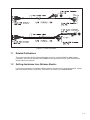
Figure 1.2 Ć Cable Assemblies . . . . . . . . . . . . . . . . . . . . . . . . . . . . . . . . . . . . . . . . . . . . . . . . . . . . . . . . . . . . . . . . 1Ć3
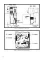
Figure 2.1 Ć Removing the Standard/Enhanced Field Supply (3Ć60 HP Drives) . . . . . . . . . . . . . . . . . . . . . . 2Ć3
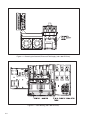
Figure 2.2 Ć Cable Routing (3 Ć 60 HP Drives) . . . . . . . . . . . . . . . . . . . . . . . . . . . . . . . . . . . . . . . . . . . . . . . . . . . 2Ć4
Figure 2.3 Ć Regulator Board Cable Connectors . . . . . . . . . . . . . . . . . . . . . . . . . . . . . . . . . . . . . . . . . . . . . . . . . 2Ć4
Figure 3.1 Ć Removing the Standard/Enhanced Field Supply (75 Ć 150 HP Drives) . . . . . . . . . . . . . . . . . . . 3Ć4
Figure 3.2 Ć Cable Routing (75 Ć 150 HP Drives) . . . . . . . . . . . . . . . . . . . . . . . . . . . . . . . . . . . . . . . . . . . . . . . . . 3Ć4
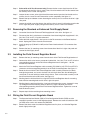
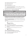
Figure 4.1 Ć Removing the Standard/Enhanced Field Supply (200 Ć 300 HP Drives) . . . . . . . . . . . . . . . . . . 4Ć4
Figure 4.2 Ć Cable Routing (200 Ć 300 HP Drives) . . . . . . . . . . . . . . . . . . . . . . . . . . . . . . . . . . . . . . . . . . . . . . . . 4Ć4
Figure A.1 Ć Field Control Loop . . . . . . . . . . . . . . . . . . . . . . . . . . . . . . . . . . . . . . . . . . . . . . . . . . . . . . . . . . . . . . . . AĆ2
Figure A.2 Ć Drive Operation Over the Constant Torque and Constant Power Range . . . . . . . . . . . . . . . . . . AĆ3
Table 1.1 Ć Verifying the Field Current Regulator Kit Matches the Drive . . . . . . . . . . . . . . . . . . . . . . . . . . . . . 1Ć1
Table 1.2 Ć Field Current Regulator Kit Contents . . . . . . . . . . . . . . . . . . . . . . . . . . . . . . . . . . . . . . . . . . . . . . . . . 1Ć1
Table A.1 Ć Field Current Feedback Scaling . . . . . . . . . . . . . . . . . . . . . . . . . . . . . . . . . . . . . . . . . . . . . . . . . . . . . AĆ3
II
1.0 INTRODUCTION
The products described in this instruction manual are manufactured or distributed by Reliance
Electric Industrial Company.
This instruction manual describes how to install and configure the optional Field Current Regulator
kits used by FlexPak 3000 drives. The Field Current Regulator, which includes a field regulator and
a field supply, can be used only in drives that have software version 3.00 (REGULATOR SW
VERSION parameter = 3.00) or later. When the kit is installed, a field control loop is enabled, allowing
the user to adjust field control functions. The field control loop operates in both the constant torque
(armature control) range and the constant power (field control) range. See Appendix A for a
description of the field control loop.
There are three Field Current Regulator kits available for use in FlexPak 3000 drives. They differ
according to the maximum motor field current they support. Use the kit that provides the maximum
motor field current (including that necessary for field forcing) required for your application. Note that
using a Field Current Regulator with a higher amperage rating than is needed will decrease control
resolution. Refer to table 1.1 to ensure you have the correct kit for your application and to table 1.2
for a list of the kit contents. See figures 1.1 and 1.2 for illustrations of the Field Current Regulator
board and cable assemblies.
Table 1.1 Ć Verifying the Field Current Regulator Kit Matches the Drive
Field Current Regulator Model Number
911FK0041
911FK0101
911FK0151
Maximum Motor Field Current
4A
10 A
15 A
Table 1.2 Ć Field Current Regulator Kit Contents
Kit Model Number
911FK0041
911FK0101
911FK0151
Part Number
707973Ć10R
64676Ć30M
707973Ć12R
707973Ć12S
69306Ć3D
69752Ć146D
D2Ć3336
707973Ć10S
64676Ć30M
707973Ć12R
707973Ć12S
69306Ć3D
69752Ć146D
D2Ć3336
707973Ć10T
64676Ć30M
707973Ć12R
707973Ć12S
69306Ć3D
69752Ć146D
D2Ć3336
Description
Printed Circuit Board Assembly
25 A Fuse, UL Class CC, 600 V
Cable Assembly
Cable Assembly
Cable Tie Wrap
Plug Cap
Instruction Manual
Printed Circuit Board Assembly
25 A Fuse, UL Class CC, 600 V
Cable Assembly
Cable Assembly
Cable Tie Wrap
Plug Cap
Instruction Manual
Printed Circuit Board Assembly
25 A Fuse, UL Class CC, 600 V
Cable Assembly
Cable Assembly
Cable Tie Wrap
Plug Cap
Instruction Manual
Quantity
1
3
1
1
8
1
1
1
3
1
1
8
1
1
1
3
1
1
8
1
1
1Ć1
(% - && &
& !( &%& ' (%%!' ('"% ' ! '& &&"' + &"'*%
#% '%& "( * &" ! ' + %) !&'%('"! !( * &%& '
%) %*% ! &"'*%
,"( ) !, $(&'"!& "% #%" & *' ' #%"('& &% ! '& !&'%('"! !( "!''
,"(% " ! '% && " "% '! &&&'! --
-
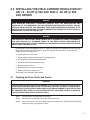
2.0 INSTALLING THE FIELD CURRENT REGULATOR KIT
ON 1.5 Ć 30 HP @ 230 VAC AND 3 Ć 60 HP @ 460
VAC DRIVES
DANGER
ONLY QUALIFIED ELECTRICAL PERSONNEL FAMILIAR WITH THE CONSTRUCTION AND
OPERATION OF THIS EQUIPMENT AND THE HAZARDS INVOLVED SHOULD INSTALL, ADJUST,
OPERATE AND/OR SERVICE THIS EQUIPMENT. READ AND UNDERSTAND THIS MANUAL IN ITS
ENTIRETY BEFORE PROCEEDING. FAILURE TO OBSERVE THIS PRECAUTION COULD RESULT IN
SEVERE BODILY INJURY OR LOSS OF LIFE.
DANGER
THE DRIVE IS AT LINE VOLTAGE WHEN CONNECTED TO INCOMING AC POWER. DISCONNECT,
TAG, AND LOCKOUT ALL INCOMING POWER TO THE DRIVE BEFORE PERFORMING THE
FOLLOWING PROCEDURE. FAILURE TO OBSERVE THIS PRECAUTION COULD RESULT IN SEVERE
BODILY INJURY OR LOSS OF LIFE.
Installing the Field Current Regulator kit on 3 Ć 60 HP drives requires completing the following steps.
When you have finished installing the kit, adjust the required drive parameters as described in
chapter 5 before using the drive.
D Opening the cover and carrier
D Removing the Standard or Enhanced Field Supply board
D Installing the Field Current Regulator board
D Wiring the Field Current Regulator board
D Replacing the drive fuses
D Reinstalling the drive carrier and cover
D Modifying the drive configuration
These steps are described in detail below.
2.1
Opening the Drive Cover and Carrier
WARNING
THE DRIVE CONTAINS PRINTED CIRCUIT BOARDS THAT ARE STATICĆSENSITIVE. AN ANTIĆSTATIC
WRIST BAND SHOULD BE WORN BY ANY PERSON WHO TOUCHES THE DRIVE'S COMPONENTS,
CONNECTORS, OR LEADS. ERRATIC MACHINE OPERATION AND DAMAGE TO, OR DESTRUCTION
OF, EQUIPMENT MAY RESULT IF THIS PROCEDURE IS NOT FOLLOWED. FAILURE TO OBSERVE
THIS PRECAUTION MAY RESULT IN BODILY INJURY.
Step 1.
Turn off, lockout, and tag power to the drive.
Step 2.
Loosen the cover retaining screws and remove the cover.
Step 3.
Loosen the captive screw at the upper right corner of the drive's Operator Interface Module
(OIM) carrier and swing open the carrier.
2Ć1
2.2
2.3
2.4
2.5
2Ć2
Removing the Standard or Enhanced Field Supply Board
Step 1.
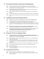
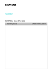
Locate the Standard or Enhanced Field Supply board in the drive. See figure 2.1.
Step 2.
Disconnect the drive's wire harness connections from the existing field supply board's 581,
582, 583, F2/35 and F1/37 spade connectors.
Step 3.
Follow the field supply board's wire harness to the P4 connector on the Power Interface
board. Unplug the harness from the P4 connector.
Step 4.
Install the plug cap (P/N 69752Ć146D) on the Power Interface board's P4 connector. See
figure 2.1.
Step 5.
Locate the field supply's four mounting screws on the outside of the drive's right side panel.
Step 6.
Remove the four mounting screws from the outside of the dive and remove the field supply
board.
Installing the Field Current Regulator Board
Step 1.
Remove the four mounting screws from the back of the Field Current Regulator board.
Step 2.
Connect the wire harness connectors labeled 581, 582, 583, F2/35 and F1/37 to the
corresponding terminals on the Field Current Regulator board. See figure 1.1.
Step 3.
Attach the Field Current Regulator cable assembly's (P/N 707973Ć12R) FLD P6 and FLD P3
connectors to the corresponding terminals on the Field Current Regulator board. See figure
1.1.
Step 4.
Working from the inside of the drive, align the Field Current Regulator board's mounting
holes with the mounting holes on the drive's right side panel. See figure 2.2.
Step 5.
Working from the outside of the drive, insert one of the mounting screws (removed in step
10) through one of the mounting holes on the drive's right side panel and into the
corresponding mounting hole on the Field Current Regulator board.
Step 6.
Repeat step 5 for the remaining three mounting holes.
Wiring the Field Current Regulator Board
Step 1.
The Operator Interface Module (OIM) or Drive Configuration Module (DCM) must be
removed to provide access to the Regulator board. Remove the screws that hold the OIM or
DCM to the carrier, and remove the OIM/DCM.
Step 2.
Remove the three screws that hold the Regulator board in place, and slide the Regulator
board slightly to the right.
Step 3.
From the back of the carrier, push the end of the Field Current Regulator cable assembly
with the REG P25 connector through the opening in the carrier (above the ribbon cable).
See figure 2.2.
Step 4.
Connect the REG P25 connector to the J25 terminal on the Regulator board. See figure 2.3.
Step 5.
Slide the Regulator board back into place and secure it with its mounting screws.
Step 6.
Reinstall the OIM/DCM.
Step 7.
Use the supplied cable ties to fasten the Field Current Regulator cable assembly to the
drive's fan or support bar.
Replacing the Drive Fuses
Step 1.
Remove the three fuses labeled 6FU, 7FU, and 8FU from the drive's fuse block.
Step 2.
Install the three provided 25 A, 600 V fuses (P/N 64676Ć30M) in the fuse block in positions
6FU, 7FU, and 8FU.
Step 1.
Close the carrier and secure it in place with its captive screw.
Step 2.
Reinstall the drive cover and secure it in place with its screws
Step 3.
Reconnect power to the drive. Hardware installation is complete.
Step 4.
Remove the lockout and tag
Step 5.
Turn on power to the drive.
Go to chapter 5 for information on setting parameters for the Field Current Regulator kit.
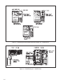
Figure 2.1 Ć Removing the Standard/Enhanced Field Supply (3Ć60 HP Drives)
2Ć3
3.0 INSTALLING THE FIELD CURRENT REGULATOR KIT
ON 40 Ć 75 HP @ 230 VAC AND 75 Ć 150 HP @ 460
VAC DRIVES
DANGER
ONLY QUALIFIED ELECTRICAL PERSONNEL FAMILIAR WITH THE CONSTRUCTION AND
OPERATION OF THIS EQUIPMENT AND THE HAZARDS INVOLVED SHOULD INSTALL, ADJUST,
OPERATE AND/OR SERVICE THIS EQUIPMENT. READ AND UNDERSTAND THIS MANUAL IN ITS
ENTIRETY BEFORE PROCEEDING. FAILURE TO OBSERVE THIS PRECAUTION COULD RESULT IN
SEVERE BODILY INJURY OR LOSS OF LIFE.
DANGER
THE DRIVE IS AT LINE VOLTAGE WHEN CONNECTED TO INCOMING AC POWER. DISCONNECT,
TAG, AND LOCKOUT ALL INCOMING POWER TO THE DRIVE BEFORE PERFORMING THE
FOLLOWING PROCEDURE. FAILURE TO OBSERVE THIS PRECAUTION COULD RESULT IN SEVERE
BODILY INJURY OR LOSS OF LIFE.
Installing the Field Current Regulator kit on 75Ć150 HP drives requires completing the following steps.
When you have finished installing the kit, adjust the required drive parameters as described in
chapter 5 before using the drive.
D Opening the cover and carrier
D Removing the Standard or Enhanced Field Supply board
D Installing the Field Current Regulator board
D Wiring the Field Current Regulator board
D Replacing the drive fuses
D Reinstalling the drive carrier and cover
D Modifying the drive configuration
These steps are described in detail below.
3.1
Opening the Drive Cover and Carrier, and Removing the AC
Disconnect
WARNING
THE DRIVE CONTAINS PRINTED CIRCUIT BOARDS THAT ARE STATICĆSENSITIVE. AN ANTIĆSTATIC
WRIST BAND SHOULD BE WORN BY ANY PERSON WHO TOUCHES THE DRIVE'S COMPONENTS,
CONNECTORS, OR LEADS. ERRATIC MACHINE OPERATION AND DAMAGE TO, OR DESTRUCTION
OF, EQUIPMENT MAY RESULT IF THIS PROCEDURE IS NOT FOLLOWED. FAILURE TO OBSERVE
THIS PRECAUTION MAY RESULT IN BODILY INJURY.
Step 1.
Turn off, lockout, and tag power to the drive.
Step 2.
Loosen the drive cover retaining screws and remove the cover..
Step 3.
Loosen the captive screw at the upper right corner of the drive's Operator Interface Module
(OIM) carrier and swing open the carrier. If the drive is equipped with an AC line disconnect,
go to step 4. Otherwise, go to step 5.
3Ć1
3.2
3.3
3.4
3Ć2
Step 4.
Drives with an AC line disconnect only: Remove the four screws that fasten the AC line
disconnect to the auxiliary chassis cover. Then, lift and remove the AC line disconnect from
the auxiliary chassis cover. See figure 3.1.
Step 5.
Loosen the two screws at the right side of the motor terminal panel to free the tabs on the
auxiliary chassis cover. Do not to remove the screws completely. See figure 3.1.
Step 6.
Remove the top and bottom screws fastening the auxiliary chassis cover to the drive's right
side panel.
Step 7.
Loosen the middle screw that fastens the auxiliary chassis cover/circuit breaker panel to the
drive's right side panel. Slightly swing out the auxiliary chassis cover and remove it.
Removing the Standard or Enhanced Field Supply Board
Step 1.
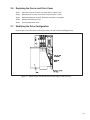
Locate the Standard or Enhanced Field Supply board in the drive. See figure 3.1.
Step 2.
Disconnect the drive's wire harness connections from the existing field supply board's 581,
582, 583, F2/35 and F1/37 spade connectors.
Step 3.
Follow the field supply board's wire harness to the P4 connector on the Power Interface
board. Unplug the harness from the P4 connector.
Step 4.
Install the plug cap (P/N 69752Ć146D) on the Power Interface board's P4 connector. See
figure 2.1.
Step 5.
Remove the four (4) mounting screws from the outside of the drive's right side panel and
remove the field supply board.
Installing the Field Current Regulator Board
Step 1.
Remove the four (4) mounting screws from the back of the Field Current Regulator board.
Step 2.
Connect the drive's wire harness connectors labeled 581, 582, 583, F2/35 and F1/37 to the
corresponding terminals on the Field Current Regulator board. See figure 1.1 for the
location of the terminals.
Step 3.
Attach the Field Current Regulator cable assembly (P/N 707973Ć12S) FLD P6 and FLD P3
connectors to the corresponding terminals on the Field Current Regulator. See figure 1.1.
Step 4.
Route the free end of the Field Current Regulator cable assembly under the fuse block,
through the grommet, and across the heat sink, to the left side of the drive following the
same path as the red and blue control wiring harness. Then run the cable assembly inside
the front of the drive to the OIM carrier. See figure 3.2.
Step 5.
Working from the inside of the drive, align the Field Current Regulator board's mounting
holes with the mounting holes on the drive's right side panel.
Step 6.
Working from the outside of the drive, insert one of the mounting screws (removed in step
13) through one of the mounting holes on the drive's right side panel and into the
corresponding mounting hole on the Field Current Regulator board. Tighten the screw to
hold the board in place.
Step 7.
Repeat step 6 for the remaining three mounting screws.
Wiring the Field Current Regulator Board
Step 1.
The Operator Interface Module (OIM) or Drive Configuration Module (DCM) must be
removed to provide access to the Regulator board. Remove the screws that hold the OIM
(or DCM) to the carrier, and remove the OIM/DCM.
Step 2.
Remove the three screws that hold the Regulator board in place, and slide the Regulator
board slightly to the right.
3.5
3.6
Step 3.
From the back of the carrier, push the end of the Field Current Regulator cable assembly
with the REG P25 connector through the opening in the carrier (above the ribbon cable).
See figure 3.2.
Step 4.
Connect the REG P25 connector to the J25 terminal on the Regulator board. See figure 2.3.
Step 5.
Slide the Regulator board back into place and secure it with its mounting screws..
Step 6.
Reinstall the OIM/DCM.
Step 7.
Use the supplied cable ties to fasten the Field Current Regulator cable assembly to the
drive's fan or support bar.
Replacing the Drive Fuses
Step 1.
Remove the three fuses labeled 6FU, 7FU, and 8FU from the drive's fuse block.
Step 2.
Install the three provided 25 A, 600 V fuses (P/N 64676Ć30M) in the fuse block in positions
6FU, 7FU, and 8FU.
Reinstalling the Auxiliary Chassis Cover, Carrier and Drive Cover
Step 1.
Insert the tabs on the left side of the auxiliary chassis cover into the slots on the right side of
the drive's motor terminal panel.
Step 2.
Align the auxiliary chassis cover over the middle screw on the drive's right side panel and
over the top and bottom mounting holes.
Step 3.
Insert the top and bottom screws into the mounting screw holes and then tighten all three
mounting screws (top, bottom, and middle).
Step 4.
Tighten the two screws on the right side of the motor terminal panel to secure the auxiliary
chassis cover's tabs in place.
Step 5.
Drives with an AC line disconnect only: Align the AC line disconnect over the mounting
holes on the auxiliary chassis cover, then secure it in place with the four screws removed
earlier.
Step 6.
Close the OIM carrier and secure it in place with its captive screw.
Step 7.
Reinstall the drive cover and secure it in place with its screws. Hardware installation is
complete.
Step 8.
Reconnect power to the drive.
Step 9.
Remove the lockout and tag.
Step 10. Turn on power to the drive.
3.7
Modifying the Drive Configuration
Go to chapter 5 for information on setting parameters for the Field Current Regulator kit.
3Ć3
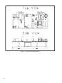
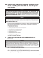
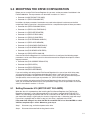
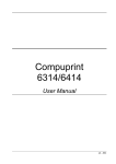
Figure 3.1 Ć Removing the Standard/Enhanced Field Supply (75 Ć 150 HP Drives)
Figure 3.2 Ć Cable Routing (75 Ć 150 HP Drives)
3Ć4
4.0 INSTALLING THE FIELD CURRENT REGULATOR KIT
ON 100 Ć 150 HP @ 230 VAC AND 200 Ć 300 HP @
460 VAC DRIVES
DANGER
ONLY QUALIFIED PERSONNEL FAMILIAR WITH THE CONSTRUCTION AND OPERATION OF THIS
EQUIPMENT AND THE HAZARDS INVOLVED SHOULD INSTALL, ADJUST, OPERATE, AND/OR
SERVICE THIS EQUIPMENT. READ AND UNDERSTAND THIS INSTRUCTION MANUAL IN ITS
ENTIRETY BEFORE PROCEEDING. FAILURE TO OBSERVE THIS PRECAUTION COULD RESULT IN
SEVERE BODILY INJURY OR LOSS OF LIFE.
DANGER
THE DRIVE IS AT LINE VOLTAGE WHEN CONNECTED TO INCOMING AC POWER. DISCONNECT,
TAG, AND LOCKOUT ALL INCOMING POWER TO THE DRIVE BEFORE PERFORMING THE
FOLLOWING PROCEDURE. FAILURE TO OBSERVE THIS PRECAUTION COULD RESULT IN SEVERE
BODILY INJURY OR LOSS OF LIFE.
&+,$$!& , !$ -**&, -$,'* #!, '& 1 *!.+ *)-!*+ '%($,!& , '$$'/!&
+,(+ & 0'- . !&!+ !&+,$$!& , #!, "-+, , *)-!* *!. (*%,*+ + +*! !&
(,* '* -+!& , *!.
D (&!& , '.* & **!*
D %'.!& , & & !$ -(($0 '*
D &+,$$!& , !$ -**&, -$,'* '*
D !*!& , !$ -**&, -$,'* '*
D ($!& , *!. -++
D !&+,$$!& , *!. **!* & '.*
D '!0!& , *!. '&!-*,!'&
+ +,(+ * +*! !& ,!$ $'/
4.1
Opening the Cover and Carrier
WARNING
THE DRIVE CONTAINS PRINTED CIRCUIT BOARDS THAT ARE STATICĆSENSITIVE. AN ANTIĆSTATIC
WRIST BAND SHOULD BE WORN BY ANY PERSON WHO TOUCHES THE DRIVE'S COMPONENTS,
CONNECTORS, OR LEADS. ERRATIC MACHINE OPERATION AND DAMAGE TO, OR DESTRUCTION
OF, EQUIPMENT MAY RESULT IF THIS PROCEDURE IS NOT FOLLOWED. FAILURE TO OBSERVE
THIS PRECAUTION MAY RESULT IN BODILY INJURY.
,( -*& ' $'#'-, & , ('/* ,' , *!.
,( %'. , ($+,! '.* *'% , *! , +! ' , *!.
,( ''+& , ,/' +*/+ '$!& , '.* !& ($ & *%'. , '.*
,( ''+& , (,!. +*/ , , -((* *! , '*&* ' , **!* & , & +/!& , **!* '(& ', , , , +*/ !+ +!& ,' +,0 ,, ,' , **!* / & !, !+
$''+&
' &', ,,%(, ,' *%'. !,
1
Step 5.
4.2
4.3
4.4
4Ć2
Locate the two plastic anchors holding the hinged mounting panel in place. Release the
anchors by inserting the tip of a flatĆbladed screwdriver into the notch on the anchors and
twist so the notch is vertical. Then swing the panel open.
Removing the Enhanced Field Supply Board
Step 1.
Locate the Enhanced Field Supply board. It is attached to the right side of the drive, behind
the line fuse panel, and can be accessed through the bottom of the drive. See figure 4.1.
Step 2.
Remove the four field supply mounting screws from the outside of the drive's right side
panel and remove the field supply.
Step 3.
Disconnect the drive's wire harness from the field supply board's 581, 582, 583, F2/35, and
F1/37 connectors.
Step 4.
Follow the field supply board's wire harness to the P4 connector on the Power Interface
board. Unplug the harness from the P4 connector.
Step 5.
Install the plug cap (P/N 69752Ć146D) on the Power Interface board's P4 connector.
Installing the Field Current Regulator Board
Step 1.
Remove the four (4) mounting screws from the back of the Field Current Regulator board.
Step 2.
Connect the drive's wire harness connectors labeled 582, 582, 583, F2/35, and F1/37 to the
corresponding terminals on the Field Current Regulator board. See figure 1.1 for the
location of the terminals.
Step 3.
Attach the Field Current Regulator cable assembly (P/N 707973Ć12S) connectors FLD P6
and FLD P3 to the corresponding terminals on the Field Current Regulator.
Step 4.
Route the free end of the Field Current Regulator cable assembly to the left side of the drive
and into the OIM carrier. Follow the path illustrated in figure 4.2. This is the same path used
by the control wiring harness.
Step 5.
Working from the inside of the bottom of the drive, align the Field Current Regulator board's
mounting holes with the mounting holes on the drive's right side panel. See figure 4.2.
Step 6.
Working from the outside of the drive, insert one of the mounting screws (removed in step
11) through one of the mounting holes on the drive's right side panel and into the
corresponding mounting hole on the Field Current Regulator board. Tighten the screw to
hold the board in place.
Step 7.
Repeat step 6 for the remaining three mounting screws.
Wiring the Field Current Regulator Board
Step 1.
The Operator Interface Module (OIM) or Drive Configuration Module (DCM) must be
removed to provide access to the Regulator board. Remove the screws that hold the OIM
(or DCM) to the carrier, and remove the OIM/DCM.
Step 2.
Remove the three screws that hold the Regulator board in place, then slide the Regulator
board slightly to the right.
Step 3.
From the back of the OIM carrier, push the end of the Field Current Regulator cable
assembly with the REG P25 connector through the opening in the carrier (above the ribbon
cable).
Step 4.
Connect the REG P25 connector to the J25 terminal on the Regulator board. See figure 2.3.
Step 5.
Slide the Regulator board back into place and secure it with its mounting screws.
Step 6.
Reinstall the OIM/DCM.
4.5
4.6
4.7
4.8
Reinstalling the OIM Carrier and Cover
Step 1.
Swing the mounting panel back into the closed position, and secure it by twisting the
notches on the two plastic anchors into a horizontal position.
Step 2.
Close the OIM carrier and secure it in place with its captive screw.
Step 3.
Reinstall the OIM/DCM cover.
Replacing the Drive Fuses
Step 1.
Locate the fuse block on the drive's line fuse panel. See figure 4.2.
Step 2.
Remove the three fuses labeled 6FU, 7FU, and 8FU from the fuse block.
Step 3.
Install the three provided 25 Amp, 600 Volt fuses (P/N 65676Ć30M) in the fuse block in
positions 6FU, 7FU, and 8FU.
Reinstalling the Drive Cover
Step 1.
Reinstall the cover over the right side of the drive.
Step 2.
Reinstall the plastic cover over the drive's line fuse panel. Hardware installation is complete.
Step 3.
Reconnect power to the drive.
Step 4.
Remove the lockout and tag.
Step 5.
Turn on power to the drive.
Modifying the Drive Configuration
Go to chapter 5 for information on setting parameters for the Field Current Regulator kit.
4Ć3
# & $ " " #% & $!
# & #" & $!
&
5.0 MODIFYING THE DRIVE CONFIGURATION
Before you can use the Field Current Regulator kit, you must set the parameters listed below in the
FlexPak 3000 drive. These parameters are described in sections 5.1 and 5.2.
D Parameter 510 (MOTOR HOT FLD AMPS)
D Parameter 511 (FIELD ECONOMY REF)
In addition, the input parameters listed below may need to be adjusted in order to tune the field
control loop. Refer to your drive's instruction manual for a complete description of these parameters.
D Parameter 501 (FIELD ECONOMY DELAY)
D Parameter 512 (FIELD LOSS THRESHOLD)
D Parameter 513 (FIELD REF REGISTER)
D Parameter 514 (FIELD PI PROP GAIN)
D Parameter 515 (FIELD PI LEAD FREQ)
D Parameter 516 (FLD FEEDBACK GAIN ADJ)
D Parameter 517 (FIELD AUTO WEAKEN)
D Parameter 518 (FLD WEAKEN THRESHOLD)
D Parameter 519 (FLD WEAKEN PROP GAIN)
D Parameter 520 (FLD WEAKEN LEAD FREQ)
D Parameter 587 (FIELD DELTA HIGH LIM)
Once the Field Current Regulator kit is installed and the drive is configured, the following output
parameters can be used. Refer to your drive instruction manual for complete descriptions of these
output parameters.
D Parameter 586 (FLD CURRENT REGULATOR)
D Parameter 588 (FIELD DELTA)
D Parameter 589 (FIELD FEEDBACK)
D Parameter 590 (FIELD REFERENCE)
If you are installing and setting up the Field Current Regulator kit as part of your initial drive setup,
and are using the quick start procedure described in the drive's instruction manual, you will be
prompted for parameter 510 (MOTOR HOT FLD AMPS). In this case, after you finish with the quick
start procedure, make sure that you set parameter 511 (FIELD ECONOMY REF).
If you are installing and setting up the Field Current Regulator kit after you have already set up the
drive, you do not need to rerun the quick start procedure. Simply access the parameters and set the
values as described in sections 5.1 and 5.2.
5.1
Setting Parameter 510 (MOTOR HOT FLD AMPS)
When the drive is first powered up after installing the Field Current Regulator, the Field Current
Regulator will operate in a fixed voltage mode until a valid value is entered for MOTOR HOT FLD
AMPS. This fixed voltage will produce 150 VDC on a 230 VAC line or 300 VDC on a 460 VAC line. If
your motor field voltage is significantly less than this, begin with step 1. Otherwise, begin with step 7
if your drive is equipped with an OIM, or step 18 if your drive is equipped with a DCM.
If the motor field voltage is less than 150 VDC on a 230 VAC line or less than 300 VDC on a 460
VAC line, complete steps 1Ć6 first. Otherwise, go to step 9.
Step 1.
Disconnect, tag, and lockout power to the drive.
Step 2.
Disconnect the motor field winding from the drive.
5Ć1
Step 3.
Reconnect power to the drive.
Step 4.
Remove the lockout and tag.
Step 5.
Turn on power to the drive.
Step 6.
After completing powerĆup diagnostics, the drive will generate a field current loss fault.
Ignore this fault.
Step 7.
Access the Fault menu by pressing the FAULT key until FAULT appears on the OIM directly
above the FAULT key.
Step 8.
Select Clear Fault Log and Reset Faults, and then press ENTER. The fault log will be
cleared and all drive faults will be reset.
If the drive is equipped with an OIM, complete the following steps to set MOTOR HOT FLD
AMPS. Otherwise, go to step 18.
Step 9.
Select MOTOR HOT FLD AMPS by taking the following path from the main menu:
Field
Field Current Regulator
Field Loop Feedback Scaling
ąąă
Step 10. Set MOTOR HOT FLD AMPS to the value printed on the motor nameplate.
Step 11. Select MEMORY SAVE by taking the following path from the main menu:
Operator Interface
Memory Operations
Step 12. Perform the Memory Save operation.
If the motor field winding was disconnected in step 2 above, perform steps 13Ć17. Otherwise,
go to step 18.
Step 13. Disconnect, tag, and lockout power to the drive.
Step 14. Reconnect the motor field winding to the drive.
Step 15. Reconnect power to the drive.
Step 16. Remove the lockout and tag.
Step 17. Turn on power to the drive.
Step 18. Access the Fault menu by pressing the FAULT key until FAULT appears on the OIM directly
above the FAULT key.
Step 19. Select Clear Fault Log and Reset Faults, and then press ENTER. The fault log will be
cleared and all drive faults will be reset. If you have an OIM, you are done with setting
parameter 510. Go to section 5.1 to set parameter 511 (FIELD ECOMOMY REF).
NOTE: If the drive is equipped with a DCM, use the following steps to set MOTOR HOT FLD AMPS.
Step 20. From the main menu, scroll to Input Parameters and press ENTER.
Step 21. Scroll to HOT FLD AMPS.
Step 22. Set HOT FLD AMPS to the value printed on the motor nameplate.
Step 23. From the main menu, scroll to Memory Operations and press ENTER.
Step 24. Scroll to Memory Save, and then perform the memory save operation.
If the motor field winding was disconnected in step 2 above, perform steps 25Ć29. Otherwise,
proceed to step 30.
Step 25. Disconnect, tag, and lockout power to the drive.
5Ć2
Step 26. Reconnect the motor field winding to the drive.
Step 27. Reconnect power to the drive
Step 28. Remove the lockout and tag.
Step 29. Turn on power the drive.
Step 30. Access the Fault menu and press ENTER.
Step 31. Scroll to Clear Fault Log and Reset Faults, and then press ENTER. The fault log will be
cleared and all drive faults will be reset.
NOTE: 5.2
Setting Parameter 511 (FIELD ECONOMY REF)
WARNING
IMPROPER SETTING OF THE FIELD ECONOMY REF PARAMETER CAN CAUSE A MOTOR
OVERVOLTAGE CONDITION. SET THE MOTOR HOT FLD AMPS PARAMETER TO THE MOTOR'S
NAMEPLATE VALUE. MAKE SURE THE FIELD ECONOMY REF PARAMETER AND/OR FIELD REF
PARAMETER (P.513) ARE ABOVE THE FIELD LOSS THRESHOLD PARAMETER (P.512). FAILURE TO
OBSERVE THIS PRECAUTION COULD RESULT IN BODILY INJURY AND DAMAGE TO THE
EQUIPMENT.
For proper drive operation, the value for parameter 511 (FIELD ECONOMY REF) must be set above
the value for parameter 512 (FIELD LOSS THRESHOLD). Note that the default value for FIELD
ECONOMY REF is 0% and that the default value for FIELD LOSS THRESHOLD is 60% of MOTOR
HOT FLD AMPS. Using the defaults for parameters 511 and 512 will result in a drive default.
See your drive's manual for more information on setting the FIELD LOSS THRESHOLD parameter
properly. Then complete the following steps.
If the drive is equipped with an OIM, complete steps 1Ć6. If the drive is equipped with a DCM,
skip to step 7.
Step 1.
Select FIELD LOSS THRESHOLD by taking the following path form the main menu:
Field
Field Current Regulator
Field Loop Configure
ąąă
Step 2.
Note the value of FIELD LOSS THRESHOLD.
Step 3.
Back up to the Field Loop Configure menu and select FIELD ECONOMY REF.
Step 4.
Set the value of FIELD ECONOMY REF to a value higher than that of FIELD LOSS
THRESHOLD.
Step 5.
Select MEMORY SAVE by taking the following path from the main menu:
Operator Interface
Memory Operations
Step 6.
Perform the Memory Save operation.
If the drive is equipped with a DCM, complete the following steps:
Step 7.
From the main menu, scroll to Input Parameters and press ENTER.
Step 8.
Scroll to FIELD LOSS THRESHOLD and note its value.
Step 9.
Scroll to FIELD ECONOMY REF.
5Ć3
'$ ' ' ) ( # '# ) ( % '" '' # '$ %#! ' !" !"( &%# '# !#%+ $%'#"& " $%&& '$ %# '# !#%+ ) " '" $%#%! ' !!#%+ &) #$%'#"
"&' '#" $%#(% #% ' (%%"' ( '#% ' & "#* #!$ '
,
Appendix A
Field Current Regulator Description
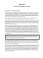
Description of the Field Control Loop
The FlexPak 3000 version 3 regulator will detect the presence of the Field Current Regulator kit at powerĆup.
The output parameter FLD CURRENT REGULATOR indicates whether or not the Field Current Regulator kit is
installed. When the Field Current Regulator kit is installed, the field current control loop operates and drive
parameters ENHANCED FLD VOLT ADJ and J21 FLD SUPPLY JUMPER are ignored. The regulated field loss
and field economy circuits become active in place of those used by the standard and enhanced field supĆ
plies. See figure A.1 for a block diagram of the field control loop.
NOTE: The regulator board jumper J20 (Field Loss Detect) is ignored when the Field Current Regulator is
installed. Therefore, setting J20 to the DISABLE position will NOT disable field loss detection.
The field control loop contains two regulators: a field current regulator and an armature voltage (counterĆEMF
or CEMF) regulator. The field control loop can be configured to decrease armature voltage when the armaĆ
ture voltage feedback (ARMATURE VOLTAGE) exceeds the FLD WEAKEN THRESHOLD voltage and the field
begins to weaken (see figures A.1 and A.2). The armature IR drop can be compensated for by using the IR
COMPENSATION parameter (P.206).
The output of the Field Current Regulator determines the firing angle of the regulated field supply gate firing
circuit. The output parameter FIELD DELTA represents the angle in degrees. If the factory defaults for the
Field Current Regulator are in effect, it will operate in a fixed voltage mode by firing the field SCRs at a fixed
angle of 117º. This will produce a field voltage of 150 VDC at 230 VAC line input or 300 VDC at 460 VAC line
input. For other motor field voltages, MOTOR HOT FLD AMPS must be set properly before the motor field is
connected. While the Field Current Regulator is producing fixed voltage, the value for MOTOR HOT FLD
AMPS will be set to 0.01 amps. After a valid value is entered for MOTOR HOT FLD AMPS, the userĆassigned
value for FIELD LOSS THRESHOLD becomes effective. The Field Current Regulator will NOT regulate field
current until a valid value for MOTOR HOT FLD AMPS is entered. While in fixed voltage mode, a field loss
fault will only occur if there is a complete loss of field current. This is similar to having a standard or enhanced
field supply installed.
CAUTION: If the factory defaults for the Field Current Regulator are not in effect (e.g., MOTOR HOT FLD
AMPS was modified via the network or CS3000), extreme care must be exercised to ensure the correct value
for MOTOR HOT FLD AMPS is present when power is applied to the drive. Failure to observe this precaution
could result in damage to, or destruction of, the equipment.
Both field loop regulators contain proportional plus integral (PI) control. There is no userĆconfigurable low
limit parameter associated with these PI blocks. The low limit is always fixed at zero. The high limit (FIELD
DELTA HI LIM) is userĆconfigurable up to 180 degrees, allowing fullĆon field voltage of 207 VDC @ 230 VAC
and 414 VDC @ 460 VAC. To regulate greater field voltages, a stepĆup transformer must be used to supply
the AC side of the Field Current Regulator.
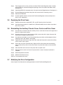
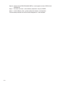
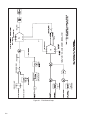
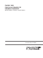
As the motor speed increases beyond base speed, the armature voltage will increase above rated voltage.
The PI block monitoring armature voltage will reduce the high limit of the PI block controlling field current. As
field current decreases, field flux and armature voltage will also decrease. Field current continues to decrease
until armature voltage is reduced to FLD WEAKEN THRESHOLD volts. Control of armature voltage during
field weakening is only permitted when a tachometer is used (FEEDBACK SELECT ≠ ARMATURE VOLTS).
Automatic field weakening can be disabled by setting FIELD AUTO WEAKEN = DISABLED. The drive can
also be operated in the constant power (field control) range by controlling the field current reference excluĆ
sively (FIELD REF REGISTER).
AĆ1
Figure A.2 Ć Drive Operation Over the Constant Torque and Constant Power Range
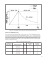
Field Current Feedback Scaling
There are three Field Current Regulator ratings: 4 amps, 10 amps, and 15 amps. The Regulator board hardĆ
ware provides three different gains for the field current feedback signal: 1, 2, and 5. The user must enter the
motor nameplate value for rated field amps (MOTOR HOT FLD AMPS) to properly scale the feedback signal.
The software will automatically select the feedback gain (in hardware) which produces the largest full scale
digital value in the analogĆtoĆdigital converter. MOTOR HOT FLD AMPS will be limited based on the rating of
the Field Current Regulator kit installed. Table A.1 shows what the software will select as the feedback gain
depending on motor hot field amps.
Table A.1 Ć Field Current Feedback Scaling
Field Current
Rating (Amps)
4
10
15
Motor Hot FLD Amps
0.11 to 0.8
0.81 to 2.00
2.01 to 4.00
0.28 to 2.00
2.01 to 5.00
5.01 to 10.00
0.55 to 4.00
4.01 to 10.00
10.01 to 20.00
Gain
5
2
1
5
2
1
5
2
1
Rated Output
(Amps)
0.8
2
4
2
5
10
4
10
15
Field Current
Resolution
(milliamps)
4
10
20
10
25
50
20
50
100
AĆ3
When the Field Current Regulator is operating in fixed voltage mode, a field current loss fault will be generĆ
ated only when there is a complete loss of field current. When the Field Current Regulator is regulating field
current (that is, not in fixed voltage mode), a field current loss fault will be generated when the field current
drops below the userĆset FIELD LOSS THRESHOLD.
The same field feedback signal used by the Field Current Regulator is used by the field loss detection circuit.
The field current feedback will be compared against a userĆentered FIELD LOSS THRESHOLD. If the feedĆ
back is less than the threshold value, a fault will be generated. FIELD LOSS THRESHOLD is entered as a perĆ
centage of
MOTOR HOT FLD AMPS (0Ć100% (speed regulator), 50Ć100% (armature voltage regulator)). FIELD ECONĆ
OMY REF must be set above FIELD LOSS THRESHOLD to avoid field loss faults when the drive enters field
economy.
A field loss fault will also occur if the digital value on the A/D converter reaches full scale (approximately 28%
above the rated field output).
The regulator board hardware jumper, J20 Field Loss Detect, is designed to allow the user to separately exĆ
cite the motor field winding, and is not intended as a means of bypassing field loss detection when using an
internal field supply. Therefore, when the Field Current Regulator kit is installed, this jumper is ignored. Note
that leaving J20 in the DISABLE position will NOT disable field loss detection.
The output parameter FIELD ECONOMY ACTIVE indicates when field economy is active. Field economy beĆ
comes active after a userĆdefined time delay (FIELD ECONOMY DELAY) from the time the motor stops or the
drive is powered up. When the Field Current Regulator is operating in fixed voltage mode, a constant field
voltage is generated, regardless of the state of FIELD ECONOMY ACTIVE.
The Field Current Regulator will provide field economy with a userĆadjustable field current reference (FIELD
ECONOMY REF). This parameter is entered as a percentage of MOTOR HOT FLD AMPS. FIELD ECONOMY
REF must be set above FIELD LOSS THRESHOLD to avoid nuisance field loss faults.
Overspeed detection is active only when a tachometer is being used (FEEDBACK SELECT ≠ ARMATURE
VOLT). Because of this, the amount of field weakening is limited when the drive is configured as a voltage
regulator (FEEDBACK SELECT = ARMATURE VOLT).
Armature overvoltage protection is always active, regardless of the type of feedback. This will reduce the
chance of overvoltaging the armature due to a weakened field. An overvoltage fault will occur when the armaĆ
ture terminal voltage exceeds 130 percent of MOTOR RATED ARM VOLTS.
AĆ4
/ 24703 Euclid Avenue / Cleveland, Ohio 44117 / (216) 266Ć7000
Printed in U.S.A.
D2Ć3336Ć1
January 1997