1
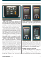
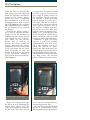
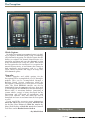
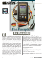
Test Bench
The Perception
Y
Is Reality
ou would be hard-pressed to find an
automotive technician who has not used an oscilloscope to diagnose a particular problem. Most
technicians either own a scope or are planning to
buy one in the near future. But with so many different scopes available to the automotive repair
industry, how will you select the scope that best
suits your needs?
If you are not familiar with using an oscilloscope,
you may want to select a scope that has preset
default setting for most of the items you will use it
for. Preset default settings save time, while also
helping the technician to become familiar with voltage, time, and trigger setting. It is equally important
that the default settings be adjustable and that the
adjustments can be saved for later references.
Do you need a hand-held scope that will handle
ignition? If so, then the scope that you choose
should have adequate primary and secondary ignition capability for most vehicle ignition systems.
Remember that all of the digital storage oscilloscopes presently marketed for automotive use do
not have the same ignition capabilities.
20
First Impressions Of The Perception
This month we turn our attention to the OTC
Perception, a digital storage oscilloscope (DSO).
Additional versions of the Perception are sold by
MAC Tools (MAC Wave Enhanced), MATCO Tools
(Reality), and Cornwell Tools (Tech Trace). Other
than slight differences in appearance, such as the
color of the outside case or the shape of the buttons
on the control panel, all versions of the tool function exactly the same.
The Perception is equipped with everything
needed to view automotive waveforms including:
•
•
•
•
•
•
Six AA Alkaline batteries
Test Leads
AC Adapter
Ignition Capacitive Probe for secondary ignition
Carrying Case
Scope User Manual and Video
Refer to the photo that begins this article for a look
at the Perception’s accessories.
July 1998
Figure 1
Figure 2
Figure 3
Main Menu
Component Menu
Perception Controls
Using The Perception
In this section, we’ll give you a quick tour of the
Perception’s basic controls. Before you purchase this
or any other DSO, we would suggest that you do a
hands-on trial of the scope under actual working
conditions, in your shop. All DSOs have their own
personalities, and there’s no better way to decide
whether that personality is compatible with yours
than to hold the scope in your own two hands.
Located just below the Perception screen are the
four-way arrow keys used to move the highlighter
selector (Figure 1). Enter and Exit buttons are located on both the left and the right of the arrow keys,
which allows the user to access the controls with
either hand. Below the four-way arrow keys are the
two Change Setting keys for changing the settings of
the scope, graph, and multimeter. Located to the left
of the Change Setting keys are the Light button (back
light on/off), Help button, and Power button. The
two controls located to the right of the Change
Setting keys are the Hold button and the Glitch button.
Turning on the Perception will automatically
bring up the Main Menu consisting of Component
Tests, Single Display, Dual Display, Advanced
Setup, and Glossary (Figure 2). Selecting Single
Display or Dual Display will automatically put you
into the manual scope mode. Selecting Component
Tests opens the Component Tests menu, which consists of Sensors, Actuators, Electrical, and Ignition.
Selecting an item from the Component Tests Menu
(Figure 3) will open additional submenus. For
instance, selecting Actuators will open an Actuator
Tests menu (Figure 4) consisting of Injector PFI/MFI
(saturated switch type), Injector TBI (peak and hold
type), Injector PNP, Mixture Ctrl Sol, EGR Ctrl Sol,
IAC Step Motor, IAC Motor, IAC Sol, Trans Shift Sol,
Turbo Boost Sol, and Glow Plug Amps. All submenu
items originating from the Component Tests menu
have preset default time, voltage and trigger settings,
meaning that selecting an item from either the
July 1998
Sensors, Actuators, Electrical, or Ignition menu will
automatically set the scope’s voltage, time, trigger
level and slope for optimum acquisition and viewing
of the waveform for that particular device.
Figure 4
Figure 5
Actuator Tests Menu
TBI Waveform
Selecting Injector TBI from the Actuator menu
will open the scope display with the voltage, time,
trigger level and slope preset to view the most common peak and hold injector patterns. Although the
settings are preset, they can be adjusted to better
view the waveform. More importantly, the adjustments can be saved as the new default settings.
Sampling An Injector Waveform
The time setting has been preset to 20 mS, meaning that the scope’s display is 20 mS wide (Figure 5).
To decrease the time setting, press the DOWN arrow
key until the trigger symbol is highlighted. Then
press the RIGHT arrow key until the 20 mS time setting is highlighted. Press the Change Settings DOWN
21
The Perception
arrow key once to decrease the
time setting to 10 mS. This will
widen the injector waveform in
respect to the scope’s display
because less time is displayed.
The waveform on a 10 mS scale
will appear twice as wide as on a 20
mS scale (Figure 6). The available
time adjustment range is from 1
mS per display to two seconds
per display.
Changing the voltage setting is
just as easy as adjusting the time
setting. Use the UP arrow key to
highlight the volt setting located
at the upper left side of the display. Then use the Change
Setting key to increase or
decrease the voltage setting per
display. Increasing the voltage
setting decreases the vertical size
of the waveform. On the other
hand, decreasing the volts per
display will increase the height
of the waveform, making it
appear taller in respect to the display (Figure 7).
set to positive or negative, which
tells the scope to start the trace
on a rising or falling voltage of
the waveform. The preset trigger
for viewing a peak and hold
injector pattern is 5 volts, negative slope. This tells the scope to
start the trace when the injector
driver pulls the negative side of
the injector’s winding from battery voltage to 5 volts. This only
happens once per injector pulse,
unless it is a Bosch-type peak
and hold injector, which cycles
above and below 5 volts at a high
frequency during the hold time.
Normally, a peak and hold
injector is pulled to ground
(approximately 0-50 mV volts)
for a fixed amount of time to
allow the injector to open.
During this time (peak time), the
voltage drop across the injector is
equal to battery/charging voltage.
The PCM then decreases the voltage drop across the injector
while holding the pintle off its
Figure 6
Figure 7
Changing Waveform Time Base
Changing Voltage Scale
Trigger level voltage and slope
are preset as well. Adjusting the
trigger level voltage tells the
scope at what point to start drawing the trace. The slope can be
seat, using less current than was
initially required to lift it.
The Bosch-type peak and hold
injector is cycled during current
limiting, rather than a direct linear
The Perception
Figure 8
Figure 9
Figure 10
Secondary Ignition Testing
located in the center of the screen above
the scope display, the Change Settings
keys can be used to select from several
Peak And Hold Injector Waveform
Dual Tracing Injector and O Sensor
types of measurements.
The Meter measurement selections
decrease in the voltage drop across the injector. The
consist of INJOT (Injector On-Time), INJPK (Injector
trigger voltage level would normally need to be
Peak Voltage), IGNBT (Ignition Burn Time), IGNPV
adjusted so the scope will not redraw the trace each
(Ignition Peak Voltage), IGNBV (Ignition Burn
time the voltage drops to 5 volts during the high freVoltage), DWELL, RMP, DUTY (Duty Cycle), WIDTH,
quency hold time. The Trigger Auto Level OFF/ON
PERIOD, FREQ (Frequency), PK-PK (Voltage Peak to
function located under the Advanced Setup menu
Peak), NEG PK (Negative Peak Voltage), POS PK
eliminates the need to make such trigger adjustments.
(Positive Peak voltage), ACAVG (AC Average
When the Trigger Auto Level is turned ON, the
Voltage), and DCAVG (DC Average Voltage). Up to
scope has the unique ability to recognize the normal
four types of measurements can be viewed simultanecharacteristics of the waveform and automatically
ously with the scope display.
setting the trigger level so that the waveform will
appear at the center of the screen. While the Trigger
Graphing Capabilities
Auto Level is turn ON, it is almost impossible to set
Because of its graphing and multimeter functions,
the trigger voltage level incorrectly. Turning the
the Perception is not limited to displaying waveTrigger Auto Level OFF, however, will set up the
forms. Although nothing replaces an oscilloscope
scope so that the trigger level must be set manually.
display, I found the graphing capability of the
Some DMMs have the ability to measure saturated
Perception to be particularly useful when dual tracswitch type injector pulse width but will read incoring an injector waveform and an O2 sensor waveform
rectly when measuring peak and hold injector pulse
(Figure 9). In the Dual Display mode, the scope’s
width. The peak time of a peak and hold injector
time per display is adjustable, but the time for both
waveform does not change. This amount of time is
displays must be set the same. Adjusting the time
physically required to open the injector. Only the
per display for Channel 1 also changes the time per
hold time varies to control fuel. In most cases a
display for Channel 2. In most cases this would not
DMM will measure only the peak time, and does not
be a problem, however the time per display must be
recognize the hold time as part of the injector pulse
set differently when dual tracing an injector wavewidth. The hold time starts at the rising edge of the
form and O2 sensor waveform in order to view an
first spike and ends at the rising edge of the last
accurate picture of both.
spike. The PCM will vary the width of the hold time
Normally the injector waveform is viewed at
only. The true pulse width is the combined peak and
approximately 10-20 mS per display. An O2 sensor
hold time (Figure 8).
waveform cycles much slower, making it difficult to
examine in the same time frame. Graphing the O2
Multimeter
sensor signal voltage gives a much clearer picture of
The Perception has the ability to simultaneously
the rich/lean PCM control by allowing the time setdisplay both the injector pulse width in mS and the
ting of the graphing display to differ from the time
waveform. By highlighting the Meter measurements
setting of the scope display.
2
24
July 1998
Scoping The Ignition
The Perception will display
both primary and secondary ignition waveforms. Some DSOs
have signal interference problems when connected to view a
primary ignition waveform,
which will stall the vehicle by
pulling the coil negative low.
The Perception has an internal
resistance, which prohibits the
scope from affecting the negative
side of the coil.
Selecting Ignition from the
Component Tests menu will bring
up the Ignition menu, which consists of PIP/SPOUT, DI Primary, DI
Secondary, EI (DIS) Pri and EI
(DIS) Sec.
Selecting DI Primary from the
Ignition menu will automatically
set up the scope’s time per display, volts per display, trigger and
slope to view the primary ignition
waveform of a Distributor type
ignition system. Selecting EI (DIS)
Pri will set up the scope to view a
Distributorless Ignition system’s
primary ignition waveform. Time,
voltage and trigger adjustments
can be made to better view the
waveform.
To view a secondary ignition
waveform, the Capacitive Probe
must be connected to the
Perception’s Channel 1 port and
ground port. Because of the wide
air gap between the rotor and distributor cap on DI systems, clamping the probe around a spark plug
wire will result in an insufficient
signal. Clamping the probe around
the coil wire (Figure 10) provides
an inductive signal that is more stable for viewing secondary ignition.
Advanced Settings
The Advanced Setup menu
(Figure 11a-c on next page) allows the
user to manually configure most
of the Perception’s operating characteristics. Here, the user can couple Channel 1 and/or Channel 2
to AC or DC, select the probe type
to be used (Volt, Amp, Ignition,
Temp), set the trigger mode to
Auto or Wait, and turn Trigger
level ON or OFF.
July 1998
Using the DOWN arrow key to
scroll to the bottom of the menu
will bring up the next Advanced
Setup menu page, which allows
the user to adjust the Horizontal
Trigger Position, turn the
Beeper On or Off, set the mV
per A for the low current Amp
Probe, select the Temp Scale
display F or C, select number of
cylinders for dwell measure-
ments, select dwell in degrees
or percent duty cycle, select
number of sparks per shaft rotation and select the memory
locations for glitch capture.
Using the DOWN arrow key to
scroll to the bottom of the second
page will bring up the final
Advanced Setup page, which
consists of Sleep Mode On/Off
and Contrast adjustments.
The Perception
Figure 11a
Figure 11b
Figure 11c
Advanced Setup Menu #1
Advanced Setup Menu #2
Advanced Setup Menu #3
Glitch Capture
By far the Perception’s most unique feature is its ability to capture a waveform glitch. Using a technology
called anomaly triggering, the Glitch Capture has the
ability to recognize the normal characteristics of a
particular waveform and store the abnormal section
of the waveform in the event of a glitch. This means
the Perception has the intelligence to recognize the
normal characteristics of waveforms that change in
both amplitude and frequency such as a wheel
speed sensor waveform and trigger on drop outs,
and abnormal spikes.
Upgrades
Future upgrades and added options for the
Perception will be accomplished via a PC through a
modem. This can be accomplished through a
Bulletin Board System connection while the
Perception is connected to a serial port via a RS232
cable. The Flash EEPROM software can also be
downloaded from the company web page, then used
to Flash Program the EEPROM of the tool through a
RS232 cable. A waveform database (consisting of
75,000 vehicle setups) is being developed for the
Perception, and will work in conjunction with
OTC’s GTI software. This will allow the user to
download and store waveforms from the Perception
to a PC.
If you would like to receive more information,
Circle No. 126 for the OTC Perception, Circle No. 127
for the Mac Wave Enhanced, Circle No. 128 for the
Matco Tools Reality, or Circle No. 129 for the Cornwell
Tech Trace on the Reader Service Card. ■
The Perception
—By Mitch Belew
26
July 1998