1
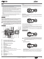
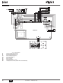
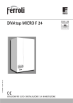
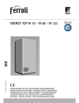
cod. 3540S131 — 12/2009 (Rev. 00)
6
ATLAS D
ISTRUZIONE PER L’USO L'INSTALLAZIONE E LA MANUTENZIONE
INSTRUCCIONES DE USO, INSTALACIÓN Y MANTENIMIENTO
KULLANMA, KURULUM VE BAKøM TALIMATLARø
INSTRUCTIONS FOR USE, INSTALLATION AND MAINTENANCE
INSTRUCTIONS D'UTILISATION, D'INSTALLATION ET D'ENTRETIEN
ȅǻǾīǴǼȈ ȋȇdzȈǾȈ, ǼīȀǹȉDZȈȉǹȈǾȈ Ȁǹǿ ȈȊȃȉdzȇǾȈǾȈ
AANWIJZINGEN VOOR GEBRUIK, INSTALLATIE EN ONDERHOUD
ATLAS D
EN
Indication during operation
1. GENERAL INSTRUCTIONS
The heating graduation marks (detail 26 - fig. 1) light up as the heating sensor temperature reaches the set value.
•
•
•
•
•
•
•
•
A heating demand (generated by the Room Thermostat or Remote Timer Control) is indicated by flashing of the hot air above the radiator (details 24 and 25 - fig. 1).
Carefully read the instructions contained in this instruction booklet.
After boiler installation, inform the user regarding its operation and give him this manual, which is an integral
and essential part of the product and must be kept with care for future reference.
Installation and maintenance must be carried out by professionally qualified personnel, according to current
regulations and the manufacturer's instructions. Do not carry out any operation on the sealed control parts.
Incorrect installation or inadequate maintenance can result in damage or injury. The Manufacturer declines
any liability for damage due to errors in installation and use or failure to follow the instructions.
Before carrying out any cleaning or maintenance operation, disconnect the unit from the power supply using
the system switch and/or the special cut-off devices.
In case of a fault and/or poor operation, deactivate the unit and do not attempt to repair it or directly intervene.
Contact professionally qualified personnel. Repair/replacement of the products must only be carried out by
professionally qualified using original spare parts. Failure to comply with the above could affect the safety of
the unit.
This unit must only be used for its intended purpose. Any other use is considered improper and therefore
dangerous.
The packing materials are potentially hazardous and must not be left within the reach of children.
The images given in this manual are a simplified representation of the product. In this representation there
may be slight and insignificant differences with respect to the product supplied.
2. OPERATING INSTRUCTIONS
bar
re s et
fig. 2
DHW (Comfort)
A DHW demand (generated by drawing domestic hot water) is indicated by flashing of
the hot water under the tap (details 12 and 13 - fig. 1). Make sure the Comfort function
(detail 15 - fig. 1) is activated
The DHW graduation marks (detail 11 - fig. 1) light up as the DHW sensor temperature
reaches the set value.
2.1 Introduction
Dear Customer,
Thank you for choosing a FERROLI boiler featuring advanced design, cutting-edge technology, high reliability and quality construction. Please read this manual carefully since
it provides important information on safe installation, use and maintenance.
comfort
bar
The boiler is arranged for connection to an external storage tank for hot
A water
production (optional). In this manual all the functions relevant to
domestic hot water production are only active with the optional hot water
tank connected as indicated in sec. 3.3
2.2 Control panel
14
2
19
5 16
15
7
9
10
ec o
co m fort
m o de
ATLAS D is a high-efficiency heat generator for domestic hot water production (optional)
and heating, suitable for operation with blown oil or gas burners. The boiler shell consists
of cast-iron elements, assembled with double cones and steel stays. The control system
is with microprocessor and digital interface with advanced temperature control functions.
11 12 1
ec o
co m fort
eco
m o de
•
Heating
re s et
fig. 3
Exclude hot water tank (economy)
Hot water tank temperature maintaining/heating can be excluded by the user. If excluded, domestic hot water will not be delivered.
When hot water tank heating is activated (default setting), the COMFORT symbol (detail
15 - fig. 1) is activated on the display, and when off, the ECO symbol (detail 15 - fig. 1)
is activated on the display
The hot water tank can be deactivated by the user (ECO mode) by pressing the button
eco comfort (detail 7 - fig. 1). To activate COMFORT mode, press the button eco comfort (detail 7 - fig. 1) again.
ecomfort
eco
c o m f o rt
2.3 Turning on and off
Boiler not electrically powered
m od e
13
27
mode
bar
ec o
co m fort
reset
re s et
fig. 4 - Boiler not electrically powered
26 24 3
25 23 4 22
21
20 18 17
6
8
fig. 1 - Control panel
18 =
19 =
20 =
21 =
22 =
23 =
24 =
25 =
26 =
27 =
DHW temperature setting decrease button
DHW temperature setting increase button
Heating system temperature setting decrease button
Heating system temperature setting increase button
Display
Summer / Winter mode selection button
Economy / Comfort mode selection button
Reset button
Unit On / Off button
"Sliding Temperature" menu button
Set DHW temperature reached
DHW symbol
DHW operation
DHW outlet temperature / setting
Eco (Economy) or Comfort mode
External sensor temperature (with optional external probe)
Appears on connecting the external Probe or the Remote Timer Control (optionals)
Room temperature (with optional Remote Timer Control)
Burner On
Antifreeze operation
Heating system pressure
Fault
Heating delivery temperature / setting
Heating symbol
Heating operation
Set heating delivery temperature reached
Summer mode
Boiler lighting
•
•
Open the fuel on-off valves.
Switch on the power to the unit.
e co
co mf ort
m od e
Key
1=
2=
3=
4=
5=
6=
7=
8=
9=
10 =
11 =
12 =
13 =
14 =
15 =
16 =
17 =
B
The antifreeze system does not work when the power and/or gas to the unit are
turned off. To avoid damage caused by freezing during long idle periods in winter, it is advisable to drain all water from the boiler, DHW circuit and system; or
drain just the DHW circuit and add a suitable antifreeze to the heating system,
complying with that prescribed in sec. 3.3.
reset
fig. 5 - Boiler lighting
•
•
•
For the following 120 seconds the display will show FH which identifies the heating
system air venting cycle.
During the first 5 seconds the display will also show the card software release.
When the message FH disappears, the boiler is ready to operate automatically
whenever domestic hot water is drawn or in case of a room thermostat demand.
cod. 3540S131 - 12/2009 (Rev. 00)
EN
23
ATLAS D
Turning the boiler off
Press the button
Room temperature adjustment (with optional remote timer control)
(detail 9 - fig. 1) for 1 second.
Using the remote timer control, set the temperature desired in the rooms. The boiler unit
will set the system water according to the required room temperature. For information on
the remote timer control, please refer to its user's manual.
Sliding Temperature
e co
com f ort
m o de
When the optional external probe is installed the control panel display (detail 5 - fig. 1)
shows the actual outside temperature read by the probe. The boiler control system operates with "Sliding Temperature”. In this mode, the temperature of the heating system
is controlled according to the outside weather conditions, to ensure high comfort and energy saving throughout the year. In particular, as the outside temperature increases the
system delivery temperature decreases according to a specific "compensation curve”.
reset
fig. 6 - Turning the boiler off
When the boiler is turned off, the electronic board is still powered.
Domestic hot water and heating operation are disabled. The antifreeze system remains
activated.
To relight the boiler, press the button
(detail 9 fig. 1) again for 1 second.
With Sliding Temperature adjustment, the temperature set with the heating buttons (details 3 and 4 - fig. 1) becomes the maximum system delivery temperature. It is advisable
to set the maximum value to allow system adjustment throughout its useful operating
range.
The boiler must be adjusted at the time of installation by qualified personnel. Adjustments can in any case be made by the user to improve comfort.
Compensation curve and curve offset
Press the button mode (detail 10 - fig. 1) once to display the compensation curve
(fig. 11), which can be modified with the DHW buttons (details 1 and 2 - fig. 1).
e co
c o mfo rt
eco
m ode
bar
Adjust the required curve from 1 to 10 according to the characteristic (fig. 13).
By setting the curve to 0, sliding temperature adjustment is disabled.
reset
fig. 7
The boiler will be immediately ready to operate whenever domestic hot water is drawn
or in case of a room thermostat demand.
2.4 Adjustments
Summer/Winter changeover
Press the button
(detail 6 - fig. 1) for 1 second.
fig. 11 - Compensation curve
Press the heating buttons (details 3 and 4 - fig. 1) to access parallel curve offset
(fig. 14), modifiable with the DHW buttons (details 1 and 2 - fig. 1).
eco
co mfort
eco
m ode
bar
res et
fig. 8
The display activates the Summer symbol (detail 27 - fig. 1): the boiler will only deliver
domestic hot water. The antifreeze system remains activated.
To deactivate Summer mode, press the button
(detail 6 - fig. 1) again for 1 second.
Heating temperature setting
Operate the heating buttons (details 3 and 4 - fig. 1) to adjust the temperature from a
min. of 30°C to a max. of 90°C; it is advisable not to operate the boiler below 45°C.
fig. 12 - Parallel curve offset
Press the button mode (detail 10 - fig. 1) again to exit parallel curve adjustment mode.
If the room temperature is lower than the required value, it is advisable to set a higher
order curve and vice versa. Proceed by increasing or decreasing in steps of one and
check the result in the room.
90
85
80
eco
co m for t
eco
9
8
7
6
5
4
70
m o de
bar
10
3
60
reset
2
50
1
40
30
fig. 9
Hot water temperature adjustment
20
20
Operate the DHW buttons (details 1 and 2 - fig. 1) to adjust the temperature from a min.
of 10°C to a max. of 65°C.
10
0
-10
OFFSET = 20
OFFSET = 40
90
85
80
10
9
8
eco
5
4
60
3
50
m ode
bar
7
6
70
e co
co m fo rt
2
40
1
30
90
85
80
10
9
8
7
20
10
fig. 10
Room temperature adjustment (with optional room thermostat)
Using the room thermostat, set the temperature desired in the rooms. If the room thermostat is not installed the boiler will keep the heating system at its setpoint temperature.
EN
5
4
3
70
2
60
1
50
40
0
-10
-20
30
20
10
0
fig. 14 - Example of parallel compensation curve shift
24
6
20
20
re set
-20
fig. 13 - Compensation curves
cod. 3540S131 - 12/2009 (Rev. 00)
-10
-20
ATLAS D
Adjustments from Remote Timer Control
A
Water system characteristics
If the Remote Timer Control (optional) is connected to the boiler, the above adjustments are managed according to that given in table 1. Also, the control panel display (detail 5 - fig. 1) shows the actual room temperature read by the
Remote Timer Control.
Table. 1
Heating temperature adjustment
Adjustment can be made from the Remote Timer Control menu
and the boiler control panel.
Domestic hot water temperature adjustment
Adjustment can be made from the Remote Timer Control menu
and the boiler control panel.
Summer/Winter switchover
Summer mode has priority over a possible Remote Timer Control heating demand.
On disabling DHW from the Remote Timer Control menu, the
boiler selects the Economy mode. In this condition, the button 7
- fig. 1 on the boiler panel is disabled.
Eco/Comfort selection
On enabling DHW from the Remote Timer Control menu, the
boiler selects the Comfort mode. In this condition it is possible
select one of the two modes with the button 7 - fig. 1 on the
boiler panel.
Both the Remote Timer Control and the boiler card manage Sliding Temperature adjustment: of the two, the boiler card Sliding
Temperature has priority.
Sliding Temperature
System water pressure adjustment
The filling pressure with system cold, read on the display, must be approx. 1.0 bar. If the
system pressure falls to values below minimum, the boiler card will activate fault F37
(fig. 15).
In the presence of water harder than 25° Fr (1°F = 10ppm CaCO3), use suitably treated
water in order to avoid possible scaling in the boiler. Treatment must not reduce the hardness to values below 15°F (Decree 236/88 for uses of water intended for human consumption). Treatment of the water used is indispensable in case of very large systems
or with frequent introduction of replenishing water in the system.
B
If water softeners are installed at the boiler cold water inlet, make sure not to
reduce the water hardness too much, as this could cause early deterioration of
the magnesium anode in the hot water tank.
Antifreeze system, antifreeze fluids, additives and inhibitors
The boiler is equipped with an antifreeze system that turns on the boiler in heating mode
when the system delivery water temperature falls under 6°C. The device will not come
on if the electricity and/or gas supply to the unit are cut off. If it becomes necessary, it is
permissible to use antifreeze fluid, additives and inhibitors only if the manufacturer of
these fluids or additives guarantees they are suitable for this use and cause no damage
to the heat exchanger or other components and/or materials of the boiler unit and system. It is prohibited to use generic antifreeze fluid, additives or inhibitors that are not expressly suited for use in heating systems and compatible with the materials of the boiler
unit and system.
Connection to a storage tank for domestic hot water production
The unit's electronic board is arranged for managing an external storage tank for domestic hot water production. Carry out the plumbing connections according to the diagram
fig. 16 (pumps and non-return valves must be supplied separately). Carry out: electrical
connections as shown in the wiring diagram in cap. 5.4. A probe FERROLImust be used
. At the next lighting, the boiler's control system recognises the presence of the hot water
tank probe and automatically configures the DHW function, activating the display and relevant controls.
8
9
e co
co mf ort
m od e
10
reset
fig. 15 - Low system pressure fault
A
Once the system pressure is restored, the boiler will activate the 120-second
venting cycle indicated on the display by FH.
11
3. INSTALLATION
fig. 16 - Diagram of connection to an external hot water tank
3.1 General Instructions
BOILER INSTALLATION MUST ONLY BE PERFORMED BY QUALIFIED PERSONNEL, IN ACCORDANCE WITH ALL THE INSTRUCTIONS GIVEN IN THIS TECHNICAL
MANUAL, THE PROVISIONS OF CURRENT LAW, THE PRESCRIPTIONS OF NATIONAL AND LOCAL STANDARDS AND THE RULES OF PROPER WORKMANSHIP.
3.2 Place of installation
The boiler must be installed in a special room with ventilation openings towards the outside in conformity with current regulations. If there are several burners or extraction units
that can work together in the same room, the ventilation openings must be sized for simultaneous operation of all the units. The place of installation must be free of flammable
objects or materials, corrosive gases, volatile substances or dusts which, sucked by the
burner fan, can obstruct the pipes inside the burner or the combustion head. The room
must be dry and not exposed to rain, snow or frost.
A
If the unit is enclosed in a cabinet or mounted alongside, a space must be provided for removing the casing and for normal maintenance operations. In particular, after boiler installation with burner on the front door, make sure the front
door can open freely without the burner striking walls or other obstacles.
3.3 Plumbing connections
The heating capacity of the unit must be previously established by calculating the building's heat requirement according to current regulations. The system must be provided
with all the components for correct and regular operation. It is advisable to install on-off
valves between the boiler and heating system allowing the boiler to be isolated from the
system if necessary.
B
The safety valve outlet must be connected to a funnel or collection pipe to prevent water spurting onto the floor in case of overpressure in the heating circuit.
Otherwise, if the discharge valve cuts in and floods the room, the boiler manufacturer cannot be held liable.
Do not use the water system pipes to earth electrical appliances.
Before installation, carefully wash all the pipes of the system to remove any residuals or
impurities that could affect proper operation of the unit.
Carry out the relevant connections according to the diagram in cap. 5 and the symbols
given on the unit.
Key
8
9
10
11
Domestic hot water outlet
Domestic cold water inlet
System delivery
System return
3.4 Burner connection
An oil or gas burner, with blown air for pressured furnaces, can be used if its operation
characteristics are suitable for the size of the boiler furnace and its overpressure. The
choice of burner must be made beforehand, following the manufacturer's instructions,
according to the work range, fuel consumption and pressures, as well as the length of
the firebox. Install the burner in compliance with the Manufacturer's instructions.
3.5 Electrical connections
Connection to the electrical grid
B
The unit's electrical safety is only guaranteed when correctly connected to an
efficient earthing system executed according to current safety standards. Have
the efficiency and suitability of the earthing system checked by professionally
qualified personnel. The manufacturer is not responsible for any damage
caused by failure to earth the system. Also make sure that the electrical system
is adequate for the maximum power absorbed by the unit, as specified on the
boiler dataplate.
The boiler is prewired and provided with a Y-cable and plug for connection to the electricity line. The connections to the grid must be made with a permanent connection and
equipped with a bipolar switch whose contacts have a minimum opening of at least 3
mm, interposing fuses of max. 3A between the boiler and the line. It is important to respect the polarities (LINE: brown wire / NEUTRAL: blue wire / EARTH: yellow-green
wire) in making connections to the electrical line. During installation or when changing
the power cable, the earth wire must be left 2 cm longer than the others.
B
The user must never change the unit's power cable. If the cable gets damaged,
switch off the unit and have it changed solely by professionally qualified personnel. If changing the electric power cable, use solely “HAR H05 VV-F” 3x0.75
mm2 cable with a maximum outside diameter of 8 mm.
cod. 3540S131 - 12/2009 (Rev. 00)
EN
25
ATLAS D
Room thermostat (optional)
Checks during operation
B
•
•
•
•
•
IMPORTANT: THE ROOM THERMOSTAT MUST HAVE VOLTAGE-FREE
CONTACTS. CONNECTING 230 V TO THE ROOM THERMOSTAT TERMINALS WILL PERMANENTLY DAMAGE THE ELECTRONIC BOARD.
When connecting time controls or a timer, do not take the power supply for
these devices from their breaking contacts Their power supply must be by
means of direct connection from the mains or with batteries, depending on the
kind of device.
Accessing the electrical terminal block
Undo the two screws “A” located on the top part of the control panel and remove the
cover.
Turn the unit on as described in sec. 2.3.
Check the seal of the fuel circuit and water systems.
Check the efficiency of the flue and air-fume ducts during boiler operation.
Make sure the water is circulating properly between the boiler and systems.
Check correct boiler lighting by performing various tests, turning it on and off with
the room thermostat or remote control.
Make sure the fuel consumption indicated on the meter matches that given in the
technical data table on sec. 5.3.
Ensure the seal of the fumebox and burner door.
Make sure the burner works properly. This check must be made with the special instruments, following the manufacturer's instructions.
Check correct programming of the parameters and carry out any required customisation (compensation curve, power, temperatures, etc.).
•
•
•
•
4.3 Maintenance
Periodical check
To ensure correct operation of the unit over time, have qualified personnel carry out a
yearly check, providing for the following:
A
•
•
•
•
•
•
•
The control and safety devices must function correctly.
The fume exhaust circuit must be perfectly efficient.
Check there are no obstructions or dents in the fuel supply and return pipes.
Clean the filter of the fuel suction line.
Measure the correct fuel consumption
Clean the combustion head in the fuel outlet zone, on the swirl disc.
Leave the burner running at full rate for approximately ten minutes, then analyse
the combustion, checking:
-
fig. 17 - Accessing the terminal board
3.6 Connection to the flue
The unit must be connected to a flue designed and built in compliance with current regulations. The pipe between the boiler and flue must be made from material suitable for
the purpose, i.e. heat and corrosion resistant. Ensure the seal at the joints and insulate
the entire pipe between boiler and flue, to prevent the formation of condensate.
•
•
All the elements specified in this manual are set correctly
Temperatures of the fumes at the flue
CO2 percentage content
The air-fume end piece and ducts must be free of obstructions and leaks
The burner and exchanger must be clean and free of deposits. For possible cleaning do not use chemical products or wire brushes.
The gas and water systems must be airtight.
The water pressure in the cold water system must be approx. 1 bar; otherwise, bring
it to that value.
The circulating pump must not be blocked.
The expansion tank must be filled.
Check the magnesium anode and replace it if necessary.
4. SERVICE AND MAINTENANCE
•
•
All adjustment, conversion, start-up and maintenance operations described below must
only be carried out by Qualified Personnel (meeting the professional technical requirements prescribed by current regulations) such as those of the Local After-Sales Technical Service.
•
•
•
FERROLI declines any liability for damage and/or injury caused by unqualified and unauthorised persons tampering with the unit.
A and damp cloth, if necessary soaked in soapy water. Do not use any abrasive
The boiler casing, control panel and aesthetic parts can be cleaned with a soft
detergents and solvents.
4.1 Adjustments
TEST mode activation
Boiler cleaning
Press the heating buttons (part. 3 and 4 - fig. 1) at the same time for 5 seconds to activate TEST mode. The boiler lights at maximum power.
1.
2.
3.
4.
The heating symbol (detail 24 - fig. 1) and DHW symbol (detail 12 - fig. 1) flash on the
display.
5.
Disconnect the power supply to the boiler.
Remove the front top and bottom panel.
Open the door by undoing the knobs.
Clean the inside of the boiler and the entire path of exhaust fumes, using a tube
brush or compressed air.
Then close the door, securing it with the knob.
To clean the burner, refer to the Manufacturer's instructions.
e co
co mfo rt
eco
4.4 Troubleshooting
mo de
Diagnostics
bar
The boiler is equipped with an advanced self-diagnosis system. In case of a boiler anomaly, the display will flash together with the fault symbol (detail 22 - fig. 1) indicating the
fault code.
re set
There are faults that cause permanent shutdown (marked with the letter “A”): to restore
operation press the RESET button (detail 8 - fig. 1) for 1 second or RESET on the optional remote timer control if installed; if the boiler fails to start, it is necessary to eliminate
the fault indicated by the operation LEDs.
Other faults (marked with the letter “F”) cause temporary shutdowns that are automatically reset as soon as the value returns within the boiler's normal working range.
fig. 18 - Operation in TEST mode
To deactivate TEST mode, repeat the activation sequence.
In any case, TEST mode is automatically deactivated after 15 minutes.
Table. 2 - Fault list
Burner adjustment
Boiler efficiency and correct operation depend above all on accurate burner adjustments.
Carefully follow the Manufacturer's instructions. The two-stage burners must have the
first stage adjusted to a power level not below the boiler's rated min. power. The power
of the second stage must not be higher than the boiler's rated max. power.
Fault
code
Fault
Possible cause
A01
Burner shutdown
(RESET ONLY OCCURS ON THE
BURNER)
Refer to the burner manual
4.2 Start-up
B
Checks to be made at first lighting, and after all maintenance operations that
involved disconnecting from the systems or an intervention on safety devices
or parts of the boiler:
Heating sensor damaged
A03
Overtemperature protection activation
Before lighting the boiler
•
•
•
•
•
•
•
26
Open any on-off valves between the boiler and the systems.
Check the seal of the fuel system.
Check correct prefilling of the expansion tank.
Fill the water system and make sure that all air contained in the boiler and the system has been vented, by opening the air valve on the boiler and any air valves on
the system.
Make sure there are no water leaks in the system, domestic hot water circuits, connections or boiler.
Check correct connection of the electrical system and efficiency of the earthing system
Make sure there are no flammable liquids or materials in the immediate vicinity of
the boiler
EN
F07
Wiring fault
Delivery sensor 1 fault
Check the circulating pump
Air in the system
Vent the system
Connector X5 not connected
Check the wiring
Wiring shorted
Wiring disconnected
Sensor damaged
F11
DHW sensor fault
F13
Wiring fault
Wiring shorted
Wiring disconnected
cod. 3540S131 - 12/2009 (Rev. 00)
Check the correct positioning
and operation of the heating
sensor
No water circulation in the system
Sensor damaged
F10
Cure
Connector X12 not connected
Check the wiring or replace
the sensor
Check the wiring or replace
the sensor
Check the wiring
ATLAS D
Fault
Possible cause
5.2 Loss of head
Cure
Sensor damaged
Pressure loss water side
Check the wiring or replace
the sensor
60
Electric mains trouble
Check the electrical system
50
Electric mains trouble
Check the electrical system
F14
Delivery sensor 2 fault
Wiring shorted
F34
Supply voltage under 170V.
F35
Mains frequency fault
F37
Incorrect system water pressure
Wiring disconnected
40
Pressure too low
Fill the system
Sensor damaged
Check the sensor
Probe damaged or wiring shorted
Check the wiring or replace
the sensor
F39
External probe fault
Probe disconnected after
activating the sliding temperature
F40
Incorrect system water pressure
Pressure too high
A
Fault
code
30
Reconnect the external probe
or disable the sliding
temperature
20
Check the system
10
Check the safety valve
Check the expansion tank
A41
Sensor positioning
Delivery sensor not inserted in
boiler shell
Check the correct positioning
and operation of the heating
sensor
F42
Heating sensor fault
Sensor damaged
Replace the sensor
F47
System water pressure sensor fault
Wiring disconnected
0
2000
2500
3000
3500
4000
4500
5000
5500
B
fig. 20 - Pressure loss
A
B
Check the wiring
5. TECHNICAL DATA AND CHARACTERISTICS
mbar
Flowrate l/h
5.3 Technical data table
5.1 Dimensions, connections and main components
500
Data
F
Unit
Model
ØC
294
850
850
34
Value
Value
D 55
D 70
D 87
no
3
4
5
6
7
Max. heating capacity
kW
32.2
45
58.8
74.7
93
(Q)
Min. heating capacity
kW
16.9
31.8
44.7
58.5
74
(Q)
Max. heat output in heating
kW
30
42
55
70
87
(P)
Min. heat output in heating
kW
16
30
42
55
70
(P)
Efficiency Pmax (80-60°C)
%
93
93.3
93.5
93.7
94
Efficiency 30%
%
94.6
94.1
93.7
93.8
95
ØB
Max. working pressure in heating
bar
6
6
6
6
6
Min. working pressure in heating
bar
0.8
0.8
0.8
0.8
1
Max. heating temperature
°C
95
95
95
95
95
L
18
23
28
33
38
Protection rating
Power supply voltage
275
10
ØC
626
Value
D 42
Number of elements
Heating water content
705
Value
D 30
Efficiency class Directive 92/42 EEC
292
275
Value
F
ØB
ØC
400
115
120 ÷ 130
ATLAS D 42
500
115
120 ÷ 130
ATLAS D 55
600
115
120 ÷ 130
ATLAS D 70
732
115
120 ÷ 130
ATLAS D 87
832
115
120 ÷ 130
X0D
X0D
X0D
X0D
X0D
230/50
230/50
230/50
230/50
230/50
Electrical power input
W
5
5
5
5
5
Empty weight
kg
127
166
205
244
283
Combustion chamber length
mm
350
450
550
650
750
Combustion chamber diameter
mm
300
300
300
300
300
mbar
0.59
0.50
0.45
0.55
1
Load loss on fumes side
ATLAS D 30
IP
V/Hz
(PMS)
(tmax)
85
11
250
250
fig. 19 - Dimensions, connections and main components
10
11
34
275
292
294
1” 1/2” system delivery
1” 1/2” system return
Heating temperature sensor
Heating system drain cock
Ø105 burner connection hole
Heating system pressure sensor
cod. 3540S131 - 12/2009 (Rev. 00)
EN
27
ATLAS D
5.4 Wiring diagram
304
32
230V
50Hz
130
42
138
139
N
L
72
211
L
N
4
5
6
7
8
9
10
11
12
13
14
15
16
17
18
T° T° 278
246
OUT
+5V
GND
DBM06A
DSP05
fig. 21 - Wiring diagram
32
42
72
130
138
139
211
246
278
304
28
Heating circulating pump (optional)
DHW temperature probe (optional)
Room thermostat (optional)
DHW circulating pump (optional)
External probe (optional)
Room unit (optional)
Burner connector
Pressure transducer
Double sensor (heating + safety)
2nd stage burner connector (version with 6 and 7 elements only)
EN
cod. 3540S131 - 12/2009 (Rev. 00)
IT
Dichiarazione di conformità
Il costruttore: FERROLI S.p.A.
Indirizzo: Via Ritonda 78/a 37047 San Bonifacio VR
dichiara che questo apparecchio è conforme alle seguenti direttive CEE:
•
•
•
•
Direttiva Apparecchi a Gas 90/396
Direttiva Rendimenti 92/42
Direttiva Bassa Tensione 73/23 (modificata dalla 93/68)
Direttiva Compatibilità Elettromagnetica 89/336 (modificata dalla 93/68)
Presidente e Legale rappresentante
Cav. del Lavoro
Dante Ferroli
ES
Declaración de conformidad
El fabricante: FERROLI S.p.A.
Dirección: Via Ritonda 78/a 37047 San Bonifacio (Verona)
declara que este equipo satisface las siguientes directivas CEE:
•
•
•
•
Directiva de Aparatos de Gas 90/396
Directiva de Rendimientos 92/42
Directiva de Baja Tensión 73/23 (modificada por la 93/68)
Directiva de Compatibilidad Electromagnética 89/336 (modificada por la 93/68)
Presidente y representante legal
Caballero del Trabajo
Dante Ferroli
ES
TR
Uygunluk beyani
ømalatçi: FERROLI S.p.A.
Adres: Via Ritonda 78/a 37047 San Bonifacio VR
bu cihazin; asagida yer alan AET(EEC) yönergelerine uygunluk içinde oldugunu beyan etmektedir:
•
•
•
•
90/396 Gazla çalistirilan üniteler için Yönetmelik
92/42 Randiman/Verimlilik Yönetmeligi
Yönerge 73/23, Düsük Voltaj (93/68 nolu direktifle degisiklige ugratildi)
89/336 Elektromanyetik Uygunluk Yönetmeligi (93/68 ile degisiklik yapilmistir)
Baskan ve yasal temsilci
øú. Dep.
Dante Ferroli
EN
Declaration of conformity
Manufacturer: FERROLI S.p.A.
Address: Via Ritonda 78/a 37047 San Bonifacio VR Italy
declares that this unit complies with the following EU directives:
•
•
•
•
Gas Appliance Directive 90/396
Efficiency Directive 92/42
Low Voltage Directive 73/23 (amended by 93/68)
Electromagnetic Compatibility Directive 89/336 (amended by 93/68)
President and Legal Representative
Cav. del Lavoro
Dante Ferroli
FR
Déclaration de conformité
Le constructeur : FERROLI S.p.A.
Adresse: Via Ritonda 78/a 37047 San Bonifacio VR
déclare que cet appareil est conforme aux directives CEE ci-dessous:
•
•
•
•
Directives appareils à gaz 90/396
Directive rendements 92/42
Directive basse tension 73/23 (modifiée 93/68)
Directive Compatibilité Electromagnétique 89/336 (modifiée 93/68)
Président et fondé de pouvoirs
Cav. du travail
Dante Ferroli
ǻȒȜȦıȘ ıȣȝȝȩȡijȦıȘȢ
EL
ȅ țĮIJĮıțİȣĮıIJȒȢ: FERROLI S.p.A.
ǻȚİȪșȣȞıȘ: Via Ritonda 78/a 37047 San Bonifacio VR
įȘȜȫȞİȚ ȩIJȚ Ș ʌĮȡȠȪıĮ ıȣıțİȣȒ ıȪȝȝȠȡijȠȪIJĮȚ ȝİ IJȚȢ ĮțȩȜȠȣșȑȢ IJȦȞ ȠįȘȖȓİȢ ǼȅȀ:
• OįȘȖȓĮ ıȣıțİȣȫȞ ıIJȠ ĮİȡȓȠȣ 90/396
• OįȘȖȓĮ ĮʌȠįȩıİȦȞ 92/42
• OįȘȖȓĮ ȤĮȝȘȜȒȢ TȐıȘȢ 73/23 (IJȡȠʌȠʌȠȚȘșİȓıĮ Įʌȩ IJȘȞ 93/68)
• OįȘȖȓĮ HȜİțIJȡȠȝĮȖȞȘIJȚțȒȢ ȈȣȝȕĮIJȩIJȘIJĮȢ 89/336 (IJȡȠʌȠʌȠȚȘșİȓıĮ Įʌȩ IJȘȞ 93/68)
Presidente e Legale rappresentante
O ȆȡȠȑįȡȠȢ țĮȚ ȞȩȝȚȝȠȢ ȑțʌȡȩıȦʌȠȢ
Dante Ferroli
NL
Conformiteitsverklaring
De fabrikant: FERROLI S.p.A.
Adres: Via Ritonda 78/a 37047 San Bonifacio VR
verklaart dat dit apparaat conform is aan de volgende EEG richtlijnen:
• Richtlijn Gastoestellen 90/396/EEG
• Richtlijn Rendementseisen 92/42/EEG
• Laagspanningsrichtlijn 73/23/EEG (gewijzigd door 93/68)
• Richtlijn Elektromagnetische compatibiliteit 89/336/EEG (gewijzigd door 93/68)
Voorzitter Raad van Bestuur en wettelijk vertegenwoordiger
Onderscheiden voor verdiensten op economisch gebied
Dante Ferroli
RU
Ⱦɟɤɥɚɪɚɰɢɹ ɫɨɨɬɜɟɬɫɬɜɢɹ
ɂɡɝɨɬɨɜɢɬɟɥɶ: FERROLI S.p.A.,
ɚɞɪɟɫ: Via Ritonda 78/a 37047 San Bonifacio VR,
ɡɚɹɜɥɹɟɬ, ɱɬɨ ɧɚɫɬɨɹɳɟɟ ɢɡɞɟɥɢɟ ɫɨɨɬɜɟɬɫɬɜɭɟɬ ɫɥɟɞɭɸɳɢɦ ɞɢɪɟɤɬɢɜɚɦ CEE:
•
•
•
•
Ⱦɢɪɟɤɬɢɜɚ ɩɨ ɝɚɡɨɜɵɦ ɩɪɢɛɨɪɚɦ 90/396
Ⱦɢɪɟɤɬɢɜɚ ɩɨ Ʉ.ɉ.Ⱦ. 92/42
Ⱦɢɪɟɤɬɢɜɚ ɩɨ ɧɢɡɤɨɦɭ ɧɚɩɪɹɠɟɧɢɸ 73/23 (ɫ ɢɡɦɟɧɟɧɢɹɦɢ, ɜɧɟɫɟɧɧɵɦɢ ɞɢɪɟɤɬɢɜɨɣ 93/68)
Ⱦɢɪɟɤɬɢɜɚ ɩɨ ɷɥɟɤɬɪɨɦɚɝɧɢɬɧɨɣ ɫɨɜɦɟɫɬɢɦɨɫɬɢ 89/336 (ɫ ɢɡɦɟɧɟɧɢɹɦɢ, ɜɧɟɫɟɧɧɵɦɢ
ɞɢɪɟɤɬɢɜɨɣ 93/68).
ɉɪɟɡɢɞɟɧɬ ɢ ɭɩɨɥɧɨɦɨɱɟɧɧɵɣ ɩɪɟɞɫɬɚɜɢɬɟɥɶ
Ʉɚɜɚɥɶɟɪɟ ɞɟɥɶ ɥɚɜɨɪɨ (ɩɨɱɟɬɧɵɣ ɬɢɬɭɥ, ɩɪɢɫɭɠɞɚɟɦɵɣ
ɝɨɫɭɞɚɪɫɬɜɨɦ ɡɚ ɡɚɫɥɭɝɢ ɜ ɪɭɤɨɜɨɞɫɬɜɟ ɩɪɨɦɵɲɥɟɧɧɨɫɬɶɸ)
Dante Ferroli
FERROLI S.p.A.
Via Ritonda 78/a
37047 San Bonifacio - Verona - ITALY
www.ferroli.it