1
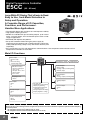
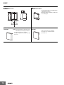
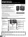
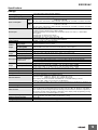
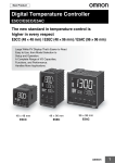
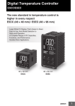
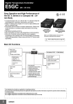
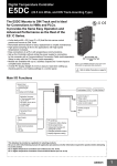
New Product
Digital Temperature Controller
E5CC/E5EC/E5AC
The new standard in temperature control is
higher in every respect
E5CC (48 × 48 mm) / E5EC (48 × 96 mm) / E5AC (96 × 96 mm)
Large White PV Display That's Easier to Read.
Easy to Use, from Model Selection to
Setup and Operation.
A Complete Range of I/O Capacities,
Functions, and Performance.
Handles More Applications.
48 × 48 mm
E5CC
48 × 96 mm
E5EC
96 × 96 mm
E5AC
1
Digital Temperature Controller
E5CC
(48 × 48 mm)
Large White PV Display That’s Easier to Read.
Easy to Use, from Model Selection to
Setup and Operation.
A Complete Range of I/O Capacities,
Functions, and Performance.
Handles More Applications.
• The white PV display with a height of 15.2 mm improves visibility.
• High-speed sampling at 50 ms.
48 × 48 mm
E5CC
• Models are available with up to 3 auxiliary outputs, up to 4 event
inputs, a transfer output, and a remote SP input to cover a wide
Refer to Safety Precautions on page 34.
range of applications.
• Short body with depth of only 60 mm.
• Set up the Controller without wiring the power supply by
connecting to the computer with a Communications Conversion
Cable (sold separately). Setup is easy with the CX-Thermo (sold
separately).
• Easy connections to a PLC with programless communications. Use component communications to link
Temperature Controllers to each other.
Main I/O Functions
Sensor Input
• Thermocouple
• Pt
• Universal analog
current/voltage input
E5CC
Dual displays: PV/SV
4-digit displays
Control Output 1
• Relay output
• Voltage output (for driving SSR)
• Current output
Indication Accuracy
• Thermocouple input:
±0.3% of PV
• Pt input: ±0.2% of PV
• Analog input:
±0.2% of FS
Control Output 2
• None
• Voltage output (for driving SSR)
Sampling Period
• 50 ms
Auxiliary Outputs
Event Inputs
• None
•2
•4
Remote SP Input
• None
•1
• PF (shift) Key
• Temperature status display
• Simple programming
• Independent heating and
cooling PID control
• Changed parameter display
• Display brightness setting
•3
Transfer Output
• None
•1
Serial Communications
• None
• RS-485
This datasheet is provided as a guideline for selecting products.
Be sure to refer to the following manuals for application precautions and other information required for operation before attempting
to use the product.
E5@C Digital Controllers User’s Manual (Cat. No. H174)
E5@C Digital Controllers Communications Manual (Cat. No. H175)
2
E5CC
Model Number Legend and Standard Models
Model Number Legend
E5CC-@@ @ @ @ @ -@@@ (Example: E5CC-RX3A5M-000)
−− − − − − −−−
A
B C D E
F
A
Model
Control outputs
1 and 2
B
C
D
No. of Power
Terminal
auxiliary supply
type
outputs voltage
E
F
Input
type
Options
Meaning
48 × 48 mm
Control output 1
Relay output
Voltage output
(for driving SSR)
Linear current output *2
Voltage output
(for driving SSR)
E5CC
RX
QX
*1 *3 CX
QQ
CQ
Linear current output *2
3
A
D
5
M
*1
000
001
*1
003
*3
004
005
006
007
Control output 2
None
None
None
Voltage output
(for driving SSR)
Voltage output
(for driving SSR)
3 (one common)
100 to 240 VAC
24 VAC/DC
Screw terminals (with cover)
Universal input
Event
Remote Transfer
HB alarm and
Communications
HS alarm
inputs
SP Input output
----------1
--2
----2
(for 3-phase
RS-485
------heaters)
--RS-485
2
--------4
--------2
Provided.
----2
Provided.
---
*1. Options with HB and HS alarms (001 and 003) cannot be selected if a current output is selected for the control output.
*2. The control output cannot be used as a transfer output.
*3. Option 004 can be selected only when "CX" is selected for the control outputs.
Heating and Cooling Control
● Using Heating and Cooling Control
A Control Output Assignment
If there is no control output 2, an auxiliary output is used as the cooling control output.
If there is a control output 2, the two control outputs are used for heating and cooling.
(It does not matter which output is used for heating and which output is used for cooling.)
B Control
If PID control is used, you can set PID control separately for heating and cooling.
This allows you to handle control systems with different heating and cooling response characteristics.
3
E5CC
Optional Products (Order Separately)
USB-Serial Conversion Cable
Model
E58-CIFQ2
Front Covers
Type
Hard Front Cover
Soft Front Cover
Model
Y92A-48H
Y92A-48D
Terminal Covers
CX-Thermo Support Software
Model
E53-COV17
E53-COV23
Model
EST2-2C-MV4
Note: The E53-COV10 cannot be used.
Refer to page 11 for the mounted dimensions.
Waterproof Packing
Model
Y92S-P8
Note: This Waterproof Packing is provided with the Digital
Temperature Controller.
Current Transformers (CTs)
Hole diameter
5.8 mm
12.0 mm
Model
E54-CT1
E54-CT3
Adapter
Model
Y92F-45
Note: Use this Adapter when the panel has already been prepared for
an E5B@ Controller.
Waterproof Cover
Model
Y92A-48N
Mounting Adapter
Model
Y92F-49
Note: This Mounting Adapter is provided with the Digital Temperature
Controller.
DIN Track Mounting Adapter
Model
Y92F-52
4
Note: CX-Thermo version 4.5 or higher is required for the E5CC.
For the system requirements for the CX-Thermo, refer to
information on the EST2-2C-MV4 on the OMRON website
(www.ia.omron.com).
E5CC
Specifications
Ratings
Power supply voltage
Operating voltage range
Power consumption
Sensor input
Input impedance
Control method
Relay output
Control
output
Auxiliary
output
Voltage output
(for driving SSR)
Current output
Number of outputs
Output specifications
Number of inputs
Event input External contact input
specifications
Transfer
output
Number of outputs
Output specifications
Setting method
Remote SP input
Indication method
Multi SP
Other functions
Ambient operating temperature
Ambient operating humidity
Storage temperature
A in model number: 100 to 240 VAC, 50/60 Hz
D in model number: 24 VAC, 50/60 Hz; 24 VDC
85% to 110% of rated supply voltage
Models with option selection of 000: 5.2 VA max. at 100 to 240 VAC, and 3.1 VA max. at 24 VAC or
1.6 W max. at 24 VDC
All other models: 6.5 VA max. at 100 to 240 VAC, and 4.1 VA max. at 24 VAC or 2.3 W max. at 24 VDC
Models with temperature inputs
Thermocouple: K, J, T, E, L, U, N, R, S, B, W, or PL II
Platinum resistance thermometer: Pt100 or JPt100
Infrared temperature sensor (ES1B): 10 to 70°C, 60 to 120°C, 115 to 165°C, or 140 to 260°C
Analog input
Current input: 4 to 20 mA or 0 to 20 mA
Voltage input: 1 to 5 V, 0 to 5 V, or 0 to 10 V
Current input: 150 Ω max., Voltage input: 1 MΩ min.
(Use a 1:1 connection when connecting the ES2-HB/THB.)
ON/OFF control or 2-PID control (with auto-tuning)
SPST-NO, 250 VAC, 3 A (resistive load), electrical life: 100,000 operations,
minimum applicable load: 5 V, 10 mA *
Output voltage: 12 VDC ±20% (PNP), max. load current: 21 mA, with short-circuit protection circuit
4 to 20 mA DC/0 to 20 mA DC, load: 500 Ω max., resolution: approx. 10,000*
3
N.O. relay outputs, 250 VAC, Models with 3 outputs: 2 A (resistive load),
Electrical life: 100,000 operations, Minimum applicable load: 10 mA at 5 V
2 or 4 (depends on model)
Contact input: ON: 1 kΩ max., OFF: 100 kΩ min.
Non-contact input: ON: Residual voltage: 1.5 V max., OFF: Leakage current: 0.1 mA max.
Current flow: Approx. 7 mA per contact
1 (only on models with a transfer output)
Contact output: 4 to 20 mA DC, load: 500 Ω max., resolution: approx. 10,000
Linear voltage output: 1 to 5 VDC, load: 1 kΩ max, resolution: Approx. 10,000
Digital setting using front panel keys
Current input: 4 to 20 mA DC or 0 to 20 mA DC (input impedance: 150 Ω max.)
Voltage input: 1 to 5 V, 0 to 5 V, or 0 to 10 V (input impedance: 1 MΩ min.)
11-segment digital display and individual indicators
Character height: PV: 15.2 mm, SV: 7.1 mm
Up to eight set points (SP0 to SP7) can be saved and selected using event inputs, key operations, or
serial communications.
Manual output, heating/cooling control, loop burnout alarm, SP ramp, other alarm functions, heater
burnout (HB) alarm (including SSR failure (HS) alarm), 40% AT, 100% AT, MV limiter, input digital
filter, self tuning, robust tuning, PV input shift, run/stop, protection functions, extraction of square root,
MV change rate limit, simple calculations, temperature status display, simple programming, moving
average of input value, and display brightness setting
-10 to 55°C (with no condensation or icing),
for 3-year warranty: -10 to 50°C (with no condensation or icing)
25% to 85%
-25 to 65°C (with no condensation or icing)
* You cannot select a relay output or current output for control output 2.
5
E5CC
Input Ranges
●Thermocouple/Platinum Resistance Thermometer (Universal inputs)
Platinum resistance
thermometer
Input type
Name
Pt100
Infrared temperature
sensor
Thermocouple
JPt100
K
J
T
E
L
U
N
R
S
B
W
PLII
10 to
70°C
60 to
120°C
115 to
165°C
120
165
140 to
260°C
2300
2300
1800
1800
1700
1700
1700
1600
1500
Temperature range (°C)
1400
1300
1300
1300
1300
1200
1100
1000
900
850
850
850
800
700
600
600
500.0
500
500.0
500.0
400.0
400
400
400.0
400
400.0
260
300
200
100.0
100
90
100
0
0.0
-100
-200
100.0
-200
-199.9
0
1
Setting
number
0.0
199.9
2
3
-20.0
-100
-20.0
6
7
8
-200
4
5
0
0
16
17
0
0
0
0
0
0
19
20
21
22
23
24
-100
-200
-199.9
-200
9
10
11
12
-200
-199.9
-200
13
14
15
18
Shaded settings are the default settings.
The applicable standards for the input types are as follows:
K, J, T, E, N, R, S, B: JIS C 1602-1995, IEC 60584-1
L: Fe-CuNi, DIN 43710-1985
U: Cu-CuNi, DIN 43710-1985
W: W5Re/W26Re, ASTM E988-1990
JPt100: JIS C 1604-1989, JIS C 1606-1989
Pt100: JIS C 1604-1997, IEC 60751
PL II: According to Platinel II electromotive force charts from BASF (previously Engelhard)
●Analog input
Input type
Input
specification
Current
4 to 20 mA 0 to 20 mA
Voltage
1 to 5 V
0 to 5 V
Usable in the following ranges by scaling:
-1999 to 9999, -199.9 to 999.9,
-19.99 to 99.99 or -1.999 to 9.999
Setting number
25
26
27
28
0 to 10 V
Setting range
6
29
E5CC
Alarm Outputs
Each alarm can be independently set to one of the following 19 alarm types. The default is 2: Upper limit. (see note.)
Auxiliary outputs are allocated for alarms. ON delays and OFF delays (0 to 999 s) can also be specified.
Note: In the default settings for models with HB or HS alarms, alarm 1 is set to a heater alarm (HA) and the Alarm Type 1 parameter is not displayed.
To use alarm 1, set the output assignment to alarm 1.
Set
value
0
Alarm function OFF
1
Upper- and lower-limit *1
ON
OFF
2
Upper-limit
ON
OFF
3
Lower-limit
ON
OFF
4
Upper- and lower-limit
range *1
ON
OFF
Upper- and lower-limit with
standby sequence *1
*5
Upper-limit with standby
sequence
ON
OFF
7
Lower-limit with standby
sequence
ON
OFF
8
Absolute-value upper-limit
ON
OFF
9
Absolute-value lower-limit
ON
OFF
10
Absolute-value upper-limit
with standby sequence
ON
OFF
11
Absolute-value lower-limit
with standby sequence
ON
OFF
12
13
LBA (alarm 1 type only)
PV change rate alarm
14
SP absolute value
upper limit
ON
OFF
15
SP absolute value
lower limit
ON
OFF
16
MV absolute value
upper limit *9
ON
OFF
17
MV absolute value
lower limit *9
ON
OFF
18
RSP absolute value
upper limit *10
ON
OFF
19
RSP absolute value
lower limit *10
ON
OFF
5
6
*1
*2
Alarm output operation
When alarm value When alarm value
X is positive
X is negative
Output OFF
Alarm type
L
H
*2
PV
SP
X
SP
PV
ON
OFF
PV
ON
OFF
X
SP
L
L
PV
*3
Case 2
PV
*4
X
SP
PV
ON
OFF
PV
ON
OFF
PV
ON
OFF
PV
ON
OFF
PV
ON
OFF
PV
ON
OFF
X
SP
X
0
X
0
X
0
X
0
H SP
H<0, L>0
|H| < |L|
X
0
SP
ON
OFF
SP
ON
OFF
MV
ON
OFF
MV
ON
OFF
RSP
ON
OFF
RSP
ON
OFF
X
0
X
0
X
0
X
0
X
0
H
SP L H
H
SP
L
H<0, L>0
|H| ≥ |L|
L SP
SP H
*3
L
H>0, L<0
|H| ≤ |L|
Set value: 4, Upper- and lower-limit range
Case 1
L
Case 3 (Always OFF)
Case 2
H SP
H<0, L>0
|H| < |L|
SP L
H
H
H>0, L<0
|H| > |L|
H
SP
L
L SP
SP H L
No alarm
Set the deviation in the set point by setting the alarm upper
limit (H) and alarm lower limit (L). The alarm is ON when the
PV is outside this deviation range.
Set the upward deviation in the set point by setting the alarm
value (X). The alarm is ON when the PV is higher than the SP
by the deviation or more.
Set the downward deviation in the set point by setting the
alarm value (X). The alarm is ON when the PV is lower than
the SP by the deviation or more.
Set the deviation in the set point by setting the alarm upper
limit (H) and alarm lower limit (L). The alarm is ON when the
PV is inside this deviation range.
A standby sequence is added to the upper- and lower-limit
alarm (1). *6
X
SP
PV
A standby sequence is added to the upper-limit alarm (2). *6
PV
A standby sequence is added to the lower-limit alarm (3). *6
X
SP
X
PV
0
X
0
PV
The alarm will turn ON if the process value is smaller than the
alarm value (X) regardless of the set point.
PV
A standby sequence is added to the absolute-value upper-limit alarm (8). *6
PV
A standby sequence is added to the absolute-value lower-limit
alarm (9). *6
X
0
X
0
The alarm will turn ON if the process value is larger than the
alarm value (X) regardless of the set point.
*7
*8
Case 3 (Always ON)
H>0, L<0
|H| > |L|
PV
SP
-
H<0, L<0
L
X
H
SP
With set values 1, 4 and 5, the upper and lower limit values can be set
independently for each alarm type, and are expressed as “L” and “H.”
Set value: 1, Upper- and lower-limit alarm
Case 1
PV
SP
H
SP
ON
OFF
X
Description of function
H<0, L<0
H<0, L>0
|H| ≥ |L|
H>0, L<0
|H| ≤ |L|
X
0
SP
This alarm type turns ON the alarm when the set point (SP) is
higher than the alarm value (X).
SP
This alarm type turns ON the alarm when the set point (SP) is
smaller than the alarm value (X).
MV
This alarm type turns ON the alarm when the manipulated
variable (MV) is higher than the alarm value (X).
MV
This alarm type turns ON the alarm when the manipulated
variable (MV) is smaller than the alarm value (X).
RSP
The alarm will turn ON when the remote SP (RSP) is larger
than the alarm value (X).
RSP
The alarm will turn ON when the remote SP (RSP) is smaller
than the alarm value (X).
X
0
X
0
X
0
X
0
X
0
*4
Set value: 5, Upper- and lower-limit with standby sequence
For Upper- and Lower-Limit Alarm Described Above *2
• Case 1 and 2
Always OFF when the upper-limit and lower-limit hysteresis overlaps.
• Case 3: Always OFF
*5. Set value: 5, Upper- and lower-limit with standby sequence
Always OFF when the upper-limit and lower-limit hysteresis overlaps.
*6 Refer to the E5@C Digital Controllers User's Manual (Cat. No. H174) for
information on the operation of the standby sequence.
*7 Refer to the E5@C Digital Controllers User's Manual (Cat. No.H174) for
information on the loop burnout alarm (LBA).
*8 Refer to the E5@C Digital Controllers User's Manual (Cat. No. H174) for
information on the PV change rate alarm.
*9 When heating/cooling control is performed, the MV absolute upper limit
alarm functions only for the heating operation and the MV absolute lower
limit alarm functions only for the cooling operation.
*10 This value is displayed only when a remote SP input is used. It functions in
both Local SP Mode and Remote SP Mode.
7
E5CC
Characteristics
Indication accuracy
(at the ambient temperature of 23°C)
Transfer output accuracy
Remote SP Input Type
Influence of temperature *2
Influence of voltage *2
Input sampling period
Hysteresis
Proportional band (P)
Integral time (I)
Derivative time (D)
Proportional band (P) for cooling
Integral time (I) for cooling
Derivative time (D) for cooling
Control period
Manual reset value
Alarm setting range
Affect of signal source resistance
Insulation resistance
Dielectric strength
resistance
Vibration
Malfunction
Shock resistance
Destruction
Malfunction
Weight
Degree of protection
Memory protection
Setup Tool
Setup Tool port
Standards
Approved standards
Conformed standards
EMC
Thermocouple:
(±0.3% of indicated value or ±1°C, whichever is greater) ±1 digit max. *1
Platinum resistance thermometer: (±0.2% of indicated value or ±0.8°C, whichever is greater) ±1 digit
Analog input:
±0.2% FS ±1 digit max.
CT input:
±5% FS ±1 digit max.
±0.3% FS max.
±0.2% FS ±1 digit max.
Thermocouple input (R, S, B, W, PL II): (±1% of PV or ±10°C, whichever is greater) ±1 digit max.
Other thermocouple input: (±1% of PV or ±4°C, whichever is greater) ±1 digit max. *3
Platinum resistance thermometer: (±1% of PV or ±2°C, whichever is greater) ±1 digit max.
Analog input: (±1%FS) ±1 digit max.
CT input: (±5% FS) ±1 digit max.
Remote SP input: (±1% FS) ±1 digit max.
50 ms
Temperature input: 0.1 to 999.9°C or °F (in units of 0.1°C or °F)
Analog input: 0.01% to 99.99% FS (in units of 0.01% FS)
Temperature input: 0.1 to 999.9°C or °F (in units of 0.1°C or °F)
Analog input: 0.1% to 999.9% FS (in units of 0.1% FS)
0 to 9999 s (in units of 1 s), 0.0 to 999.9 s (in units of 0.1 s) *4
0 to 9999 s (in units of 1 s), 0.0 to 999.9 s (in units of 0.1 s) *4
Temperature input: 0.1 to 999.9°C or °F (in units of 0.1°C or °F)
Analog input: 0.1% to 999.9% FS (in units of 0.1% FS)
0 to 9999 s (in units of 1 s), 0.0 to 999.9 s (in units of 0.1 s) *4
0 to 9999 s (in units of 1 s), 0.0 to 999.9 s (in units of 0.1 s) *4
0.1, 0.2, 0.5, 1 to 99 s (in units of 1 s)
0.0 to 100.0% (in units of 0.1%)
-1999 to 9999 (decimal point position depends on input type)
Thermocouple: 0.1°C/Ω max. (100 Ωmax.)
Platinum resistance thermometer: 0.1°C/Ω max. (10 Ω max.)
20 MΩ min. (at 500 VDC)
2,300 VAC, 50 or 60 Hz for 1 min (between terminals with different charge)
10 to 55 Hz, 20 m/s2 for 10 min each in X, Y, and Z directions
10 to 55 Hz, 20 m/s2 for 2 hrs each in X, Y, and Z directions
100 m/s2, 3 times each in X, Y, and Z directions
300 m/s2, 3 times each in X, Y, and Z directions
Controller: Approx. 120 g, Mounting Bracket: Approx. 10 g
Front panel: IP66, Rear case: IP20, Terminals: IP00
Non-volatile memory (number of writes: 1,000,000 times)
CX-Thermo version 4.5 or higher
E5CC top panel: An E58-CIFQ2 USB-Serial Conversion Cable is used to connect to a USB port on
the computer. *5
UL 61010-1, CSA C22.2 No. 611010-1 (evaluated by UL), KOSHA certified (some models) *6, Korean
Radio Waves Act (Act 10564)
EN 61010-1 (IEC 61010-1): Pollution level 2, overcurrent category II, Lloyd's standards *7
EMI:
EN61326
Radiated Interference Electromagnetic Field Strength: EN 55011 Group 1, class A
Noise Terminal Voltage:
EN 55011 Group 1, class A
EMS:
EN 61326
ESD Immunity:
EN 61000-4-2
Electromagnetic Field Immunity:
EN 61000-4-3
Burst Noise Immunity:
EN 61000-4-4
Conducted Disturbance Immunity:
EN 61000-4-6
Surge Immunity:
EN 61000-4-5
Voltage Dip/Interrupting Immunity:
EN 61000-4-11
*1 The indication accuracy of K thermocouples in the -200 to 1300°C range, T and N thermocouples at a temperature of -100°C max., and U and
L thermocouples at any temperatures is ±2°C ±1 digit max. The indication accuracy of the B thermocouple at a temperature of 400°Cmax. is
not specified. The indication accuracy of B thermocouples in the 400 to 800°Crange is ±3°C max. The indication accuracy of the R and S
thermocouples at a temperature of 200°C max. is ±3°C ±1 digit max. The indication accuracy of W thermocouples is ±0.3 of PV or ±3°C,
whichever is greater, ±1 digit max. The indication accuracy of PL II thermocouples is ±0.3 of PV or ±2°C, whichever is greater, ±1 digit max.
*2 Ambient temperature: -10°C to 23°C to 55°C, Voltage range: -15% to 10% of rated voltage
*3 K thermocouple at -100°C max.: ±10°C max.
*4 The unit is determined by the setting of the Integral/Derivative Time Unit parameter.
*5 External communications (RS-485) and USB-serial conversion cable communications can be used at the same time.
*6 Access the following website for information on certified models. http://www.ia.omron.com/support/models/index.html
*7 Refer to information on maritime standards in Shipping Standards on page 36 for compliance with Lloyd's Standards.
8
E5CC
USB-Serial Conversion Cable
Windows 2000, XP, Vista, or 7
Applicable software
CX-Thermo version 4.5 or higher
Applicable models
E5CC/E5EC/E5AC and E5CB
USB interface standard
Conforms to USB Specification 1.1.
DTE speed
38400 bps
Connector
specifications
Computer: USB (type A plug)
Digital Temperature Controller:
Setup Tool port
Power supply
Bus power (Supplied from USB host controller.)*
Power supply voltage
5 VDC
Current consumption
450 mA max.
Output voltage
4.7±0.2 VDC
(Supplied from USB-Serial Conversion Cable to
the Digital Temperature Controller.)
Output current
250 mA max.
(Supplied from USB-Serial Conversion Cable to
the Digital Temperature Controller.)
Ambient operating
temperature
0 to 55°C (with no condensation or icing)
Ambient operating
humidity
10% to 80%
Storage temperature
-20 to 60°C (with no condensation or icing)
Storage humidity
10% to 80%
Altitude
2,000 m max.
Weight
Approx. 120 g
Windows is a registered trademark of Microsoft Corporation in the
United States and or other countries.
* Use a high-power port for the USB port.
Note: A driver must be installed in the personal computer. Refer to
installation information in the operation manual for the
Conversion Cable.
Communications Specifications
Transmission line
connection method
RS-485: Multipoint
Communications
RS-485 (two-wire, half duplex)
Synchronization
method
Start-stop synchronization
Protocol
CompoWay/F, or Modbus
Baud rate
19200, 38400, or 57600 bps
Transmission code
ASCII
Data bit length*
7 or 8 bits
Stop bit length*
1 or 2 bits
Error detection
Vertical parity (none, even, odd)
Block check character (BCC) with
CompoWay/F or CRC-16 Modbus
Flow control
None
Interface
RS-485
Retry function
None
Communications buffer 217 bytes
Communications
response wait time
0 to 99 ms
Default: 20 ms
* The baud rate, data bit length, stop bit length, and vertical parity can
be individually set using the Communications Setting Level.
Communications Functions
Programless
communications*
• You can use the memory in the PLC to read
and write E5@C parameters, start and stop
operation, etc. The E5@C automatically
performs communications with PLCs. No
communications programming is required.
Number of connected Temperature
Controllers: 16 max.
Applicable PLCs
OMRON PLCs
SYSMAC CS Series, CJ Series, or CP
Series
Mitsubishi Electric PLCs
MELSEC Q Series or L Series
• When Temperature Controllers are
connected, the parameters can be copied from
the Temperature Controller that is set as the
master to Temperature Controllers that are set
as slaves.
Number of connected Temperature
Controllers: 16 max. (including master)
Communications
between components*
• When Temperature Controllers are
connected, set points and RUN/STOP
commands can be sent from the Temperature
Controller that is set as the master to
Temperature Controllers that are set as
slaves.
Slope and offsets can be set for the set point.
Number of connected Temperature
Controllers: 16 max. (including master)
* A Temperature Controller with version 1.1 or higher is required.
Current Transformer (Order Separately)
Ratings
Dielectric strength
Vibration resistance
Weight
Accessories
(E54-CT3 only)
1,000 VAC for 1 min
50 Hz, 98 m/s2
E54-CT1: Approx. 11.5 g,
E54-CT3: Approx. 50 g
Armatures (2)
Plugs (2)
Heater Burnout Alarms and SSR Failure
Alarms
CT input (for heater
current detection)
Maximum heater
current
Input current
indication accuracy
Heater burnout
alarm setting range
*1
SSR failure alarm
setting range *2
Models with detection for singlephase
heaters: One input
Models with detection for singlephase or
three-phase heaters: Two inputs
50 A AC
±5% FS ±1 digit max.
0.1 to 49.9 A (in units of 0.1 A)
Minimum detection ON time: 100 ms *3
0.1 to 49.9 A (in units of 0.1 A)
Minimum detection OFF time: 100 ms *4
*1 For heater burnout alarms, the heater current will be measured
when the control output is ON, and the output will turn ON if the
heater current is lower than the set value (i.e., heater burnout
detection current value).
*2 For SSR failure alarms, the heater current will be measured when
the control output is OFF, and the output will turn ON if the heater
current is higher than the set value (i.e., SSR failure detection
current value).
*3 The value is 30 ms for a control period of 0.1 s or 0.2 s.
*4 The value is 35 ms for a control period of 0.1 s or 0.2 s.
Electrical Life Expectancy Curve for
Relays (Reference Values)
Life (× 104 operations)
Applicable OS
500
300
100
50
30
10
5
E5CC
250 VAC, 30 VDC
(resistive load)
cosφ = 1
3
1
0
1
2
3
4
5
6
Switching current (A)
9
E5CC
External Connections
E5CC
Control output 1
Relay output
250 VAC, 3A
(resistive load)
Voltage output
(for driving SSR)
12 VDC, 21 mA
Current output
0 to 20 mA DC
4 to 20 mA DC
Load: 500 Ω max.
E5CC-@@ 3 @ 5 M - @ @ @
(1)
Auxiliary outputs 1 to 3
(1) Control outputs 1, 2
RX
QX
Models with
1 Relay
Output
QQ
CX
OUT1
+
- Q
1
2
3
(5) Sensor (Temperature/Analog) Input
TC
V
Pt
I
A
+ 4
4
4
4
B
mA
- 5
- 5
5
5
B
V
6
6
6
+ 6
+
(6) Options
001
Event Inputs 1
and 2, and CT1
13
14
EV1
15
EV2
CT1
16
17
18
003
Communications
(RS-485), CT1,
and CT2
B(+)
RS-485
A(-)
CT1
COM
CT2
The E5CC is set for a K-type thermocouple (input type = 5) by
default. An input error (s.err) will occur if the input type setting does
not agree with the temperature sensor. Check the input type.
(2) Auxiliary Outputs
Auxiliary outputs 1, 2, 3
Models with 2 Outputs: Current Output
and Voltage (for Driving SSR)
OUT1
+Q
- Q
+ OUT2
OUT1 1
+
- C
2
3
1
2
3
OUT1
+C
- Q
+ OUT2
7
8
9
10
1
13
7
2
14
8
3
15
9
4
16
10
5
17
11
6
18
12
Auxiliary output 2
Auxiliary output 1
●
●
11
11
12
12
(no polarity)
004
Communications
(RS-485), and
Event Inputs 3 and 4
13
14
B(+)
RS-485
A(-)
15
15
16
16
17
18
EV3
EV4
005
Event Inputs
1 to 4
13
14
17
18
Isolation/Insulation Block Diagrams
Models with 3 Auxiliary Outputs
Sensor input, CT inputs, and remote SP input
Communications and event inputs
Voltage output (for driving SSR),
current output, and transfer output
Relay output
Auxiliary outputs 1, 2, 3
: Reinforced insulation
: Functional isolation
Note: Auxiliary outputs 1 to 3 are not isolated.
10
Auxiliary output 3
(3) Input Power Supply
100 to 240 VAC
24 VAC/VDC
EV1
EV2
EV3
EV4
13
14
007
Event Inputs
1 and 2, and
Remote SP Input
13
14
006
Event Inputs
1 and 2, and
Transfer Output
15
13
14
EV1
15
EV2
16
16
17
17
18
18
Note: 1. The application of the terminals depends on the model.
2. Do not wire the terminals that are shown with a gray background.
3. When complying with EMC standards, the cable that connects the sensor must be 30 m or less.
If the cable length exceeds 30 m, compliance with EMC standards will not be possible.
4. Connect M3 crimped terminals.
Power
supply
(6)
CQ
Models with 2
Voltage Outputs
(for Driving SSR)
Models with
1 Current
Output
Models with 1
Voltage Output
(for Driving SSR)
OUT1 1
R
2
3
1
2
3
Relay outputs
Models with 3 auxiliary
outputs: 250 VAC, 2 A
(resistive load)
Control output 2
Voltage output
(for driving SSR)
12 VDC, 21 mA
(2) (3) (4) (5)
↑
Terminal type
EV1
+
+V
I
-
EV2
15
+
16
V +
mA 17
18
E5CC
Nomenclature
E5CC
Front panel
Temperature unit
No. 1 display
Operation indicators
PV or specified parameter
Top View of E5CC
No. 2 display
SP or specified parameter value
Top-panel Setup Tool port
Use the U D Keys to set the
parameter.
Press O Key once to go to Adjustment Level.
Use S Key to change the digit (default setting).
Press O Key for at least 3 seconds to go to Initial Setting Level.
Use the M Key to change to another parameter.
Dimensions
(Unit: mm)
Controllers
E5CC
Panel Cutout
Mounted Separately
Group Mounted
73.1
4
(48 × number of units - 2.5)+1.0
0
60
1
48 × 48
45+0.6
0
44.8 × 44.8 48.8 58
Group mounting does
not allow waterproofing.
60 min.
45+0.6
0
Waterproof Packing
(Accessory)
Mounting Adapter
(Accessory)
45+0.6
0
Terminal Cover
(E53-COV17)
(Sold separately)
The Setup Tool port is on the top of the Temperature Controller.
It is used to connect the Temperature Controller to the computer
to use the Setup Tool.
The E58-CIFQ2 USB-Serial Conversion Cable is required to
make the connection.
Refer to the instructions that are provided with the USB-Serial
Conversion Cable for the connection procedure.
Note: Do not leave the USB-Serial Conversion Cable
connected when you use the Temperature Controller.
• Recommended panel thickness is 1 to 5 mm.
• Group mounting is not possible in the vertical direction. (Maintain
the specified mounting space between Controllers.)
• To mount the Controller so that it is waterproof, insert the
waterproof packing onto the Controller.
• When two or more Controllers are mounted, make sure that the
surrounding temperature does not exceed the allowable operating
temperature specified in the specifications.
• To attach the USB-Serial Conversion Cable to the control panel,
use a panel thickness of 1 to 2.5 mm.
Accessories (Order Separately)
● USB-Serial Conversion Cable
E58-CIFQ2
(2,109.1)
250
(87)
(13)
1,740
(5) (15)
(250)
LED (RD)
USB connector (type A plug)
Serial connector
LED (PWR)
LED (SD)
● Terminal Covers
E53-COV17
48
● Terminal Covers
E53-COV23 (Three Covers provided.)
2
3.8
48.8
10
Terminal Cover
(E53-COV23)
22
44.8
9.1
11
E5CC
● Waterproof Packing
Y92S-P8 (for DIN 48 × 48)
The Waterproof Packing is provided with the Temperature Controller.
Order the Waterproof Packing separately if it becomes lost or damaged.
The Waterproof Packing can be used to achieve an IP66 degree of protection.
(Deterioration, shrinking, or hardening of the waterproof packing may occur depending on the
operating environment. Therefore, periodic replacement is recommended to ensure the level of
waterproofing specified in IP66. The time for periodic replacement depends on the operating
environment. Be sure to confirm this point at your site.
Consider three years a rough standard.)
The Waterproof Packing does not need to be attached if a waterproof structure is not required.
● Current Transformers
E54-CT1
21
15
Thru-current (Io) vs. Output Voltage (Eo)
(Reference Values)
E54-CT1
2.8
5.8 dia.
7.5
25
Maximum continuous heater current: 50 A (50/60 Hz)
Number of windings:
400±2
Winding resistance:
18±2 Ω
3
Output voltage (Eo) V (r.m.s.)
10.5
40
Two, 3.5 dia.
10
30
100V
Frequency: 50 Hz
∞
1kΩ
10
Distortion
factor
10%
1
3%
1%
100mV
100Ω
10
E54-CT3
2.36 dia.
30
RL=10Ω
1
12 dia.
9
100μV
10
1
40 × 40
10
100mA
1
10
100 1,000A
Thru-current (Io) A (r.m.s.)
Thru-current (Io) vs. Output Voltage (Eo)
(Reference Values)
E54-CT3
Two, M3 (depth: 4)
15
E54-CT3 Accessory
• Armature
Approx. 3 dia.
Connection Example
Plug
Armature
Lead
18
• Plug
Output voltage (Eo) V (r.m.s.)
Maximum continuous heater current: 120 A (50/60 Hz)
(Maximum continuous heater current for an OMRON
Digital Temperature Controller is 50 A.)
Number of windings:
400±2
Winding resistance:
8±0.8 Ω
30
100V
Frequency: 50 Hz
Distortion
factor
10%
3%
1%
∞
1kΩ
500Ω
10
1
100mV
100Ω
50Ω
10
RL=10Ω
1
Approx. 6 dia.
100μV
(22)
10
1
10
100mA
1
10
100 1,000A
Thru-current (Io) A (r.m.s.)
12
E5CC
● Adapter
Y92F-45
Note: 1. Use this Adapter when the Front Panel has already been prepared for the E5B@.
2. Only black is available.
3. You cannot use the E58-CIFQ2 USB-Serial Conversion Cable if you use the Y92F-45 Adapter. To use the USB-Serial
Conversion Cable to make the settings, do so before you mount the Temperature Controller in the panel.
Fixture (Accessory)
76
4.7
69.6 to 77.6
72 × 72
67 × 67 87
Mounted to E5CC
Panel (1 to 8 mm)
Mounting Adapter
Y92F-30
(Accessory)
72 × 72
48 × 48
2.2
4.7
62.8
To back of the E5CC
● DIN Track Mounting Adapter
Y92F-52
Note: This Adapter cannot be used together with the Terminal Cover.
Remove the Terminal Cover to use the Adapter.
61
3.5
50
This Adapter is used to mount the
E5CC to a DIN Track.
If you use the Adapter, there is no
need for a plate to mount in the
panel or to drill mounting holes in
the panel.
38
Mounted to E5CC
48
80.5
13
E5CC
● Watertight Cover
● Mounting Adapter
Y92A-48N
Y92F-49
21.9
14
The Mounting Adapter is provided with the
Temperature Controller.
Order this Adapter separately if it becomes
lost or damaged.
(2)
87.7
69
79.2
12
67.6
● Protective Cover
● Protective Cover
Y92A-48D
Y92A-48H
Note: This Protective Cover cannot be used
if the Waterproof Packing is installed.
This Protective Cover is soft type.
It is able to operate the controller with using
this cover.
14
This Protective Cover is hard type.
Please use it for the mis-operation
prevention etc.
MEMO
15
Digital Temperature Controller
E5EC/E5AC
(48 × 96 mm/96 × 96 mm)
Large White PV Display That’s Easier to Read.
Easy to Use, from Model Selection to
Setup and Operation.
A Complete Range of I/O Capacities,
Functions, and Performance.
Handles More Applications.
• A white LCD PV display with a height of approx. 18 mm for the
E5EC and 25 mm for the E5AC improves visibility.
• Tool ports are provided both on the top panel and the front panel.
96 × 96 mm
48 × 96 mm
Set up the Controller without wiring the power supply by
E5AC
E5EC
connecting to the computer with a Communications Conversion
Cable (sold separately). Setup is easy with the CX-Thermo (sold
Refer to Safety Precautions on page 34.
separately).
• High-speed sampling at 50 ms.
• Models are available with up to 4 auxiliary outputs, up to 6 event inputs, a transfer output, and a remote SP input
to cover a wide range of applications.
• Short body with depth of only 60 mm.
• Easy connections to a PLC with programless communications. Use component communications to link
Temperature Controllers to each other.
• The new position-proportional control models allow you to control valves as well.
Main I/O Functions
Sensor Input
• Thermocouple
• Pt
• Universal analog
current/voltage input
E5EC
E5AC
Three-level Display
PV, SV, and MV displayed
at the same time.
4-digit
displays
Indication Accuracy
• Thermocouple input:
±0.3% of PV
• Pt input: ±0.2% of PV
• Analog input: ±0.2% of FS
Control Output 1
• Relay output
• Voltage output (for driving SSR)
• Current output
Sampling Period
Control Output 2
• Voltage output (for driving SSR)
• Relay output
• Current output
• 50 ms
Event Inputs
• None
•2
•4
•6
Remote SP Input
• None
•1
• PF (shift) Key
• Setup Tool port on front panel
• Temperature status display
• Simple programming
• Independent heating and
cooling PID control
• Changed parameter display
• Display brightness setting
Auxiliary Outputs
•4
Transfer Output
• None
•1
Serial Communications
• None
• RS-485
This datasheet is provided as a guideline for selecting products.
Be sure to refer to the following manuals for application precautions and other information required for operation before attempting
to use the product.
E5@C Digital Controllers User’s Manual (Cat. No. H174)
E5@C Digital Controllers Communications Manual (Cat. No. H175)
16
E5EC/E5AC
Model Number Legend and Standard Models
Model Number Legend
E5EC-@@
@ @ @ @ -@@@ (Example: E5EC-RX4A5M-000)
−− − − − − −−−
A
B C D E
F
E5AC-@@ @ @ @ @ -@@@ (Example: E5AC-RX4A5M-000)
−− − − − − −−−
A
B C D E
F
A
Model
B
C
D
E
F
No. of auxil- Power
Terminal Input
iary out- supply
Options
type
type
puts
voltage
Control outputs
1 and 2
Meaning
48 × 96 mm
96 × 96 mm
Control output 1
Relay output
Voltage output
(for driving SSR)
Linear current output
Voltage output
(for driving SSR)
Voltage output
(for driving SSR)
Relay output
E5EC
E5AC
RX
QX
*2 CX
QQ
QR
RR
*2 CC
CQ
PR
*3 4
A
D
Control outputs 1 and 2
For RX,
QX, QQ,
For CX or
QR, RR, or CC
CQ
5
M
For PR
Selectable Selectable Selectable
Selectable Selectable
Selectable
Option
selection
conditions
*1
Selectable
000
004
005
009
Selectable
Selectable
Selectable
Selectable Selectable
010
011
013
014
Control output 2
None
None
None
Voltage output
(for driving SSR)
Relay output
Relay output
Linear current outLinear current output
put
Voltage output
Linear current output
(for driving SSR)
Position-proportionPosition-proportional relay output
al relay output
4 (auxiliary outputs 1 and 2 with same common and auxiliary outputs 3 and 4 with same common)
100 to 240 VAC
24 VAC/DC
Screw terminals (with cover)
Universal input
HB alarm
Event Remote Transfer
and
Communications
inputs SP Input output
HS alarm
------------RS-485
2
--------4
----2
(for 3-phase
RS-485
2
----heaters)
1
--4
----1
--6
Provided. Provided.
----6
Provided. Provided.
--RS-485
4
Provided. Provided.
*1. The options that can be selected depend on the type of control output.
*2. The control output cannot be used as a transfer output.
*3. A model with four auxiliary outputs must be selected.
Heating and Cooling Control
l Using Heating and Cooling Control
A Control Output Assignment
If there is no control output 2, an auxiliary output is used as the cooling control output.
If there is a control output 2, the two control outputs are used for heating and cooling.
(It does not matter which output is used for heating and which output is used for cooling.)
B Control
If PID control is used, you can set PID control separately for heating and cooling.
This allows you to handle control systems with different heating and cooling response characteristics.
17
E5EC/E5AC
Optional Products (Order Separately)
USB-Serial Conversion Cable
Model
E58-CIFQ2
Communications Conversion Cable
Note: Always use this product together with the E58-CIFQ2.
This Cable is used to connect to the front-panel Setup Tool
port.
Terminal Covers
Model
E53-COV24
Waterproof Packing
Model
Y92S-P9
Y92S-P10
Note: This Waterproof Packing is provided with the Digital
Temperature Controller.
Waterproof Cover
Applicable Controller
E5EC
E5AC
Model
Y92A-49N
Y92A-96N
Front Port Cover
Model
Y92S-P7
Note: This Front Port Cover is provided with the Digital Temperature
Controller.
Mounting Adapter
Model
Y92F-51
(Two Adapters are included.)
Note: This Mounting Adapter is provided with the Digital Temperature
Controller.
18
Hole diameter
5.8 mm
12.0 mm
Model
E54-CT1
E54-CT3
CX-Thermo Support Software
Model
E58-CIFQ2-E
Applicable Controller
E5EC
E5AC
Current Transformers (CTs)
Model
EST2-2C-MV4
Note: CX-Thermo version 4.5 or higher is required for the E5EC.
For the system requirements for the CX-Thermo, refer to
information on the EST2-2C-MV4 on the OMRON website
(www.ia.omron.com).
E5EC/E5AC
Specifications
Ratings
Power supply voltage
Operating voltage range
E5EC
Power consumption
E5AC
Sensor input
Input impedance
Control method
Relay output
Control
output
Auxiliary
output
Voltage output
(for driving SSR)
Current output
Number of outputs
Output specifications
Number of inputs
Event input External contact input
specifications
Transfer
output
Number of outputs
Output specifications
Remote SP input
Potentiometer input
Setting method
Indication method
Multi SP
Bank switching
Other functions
Ambient operating temperature
Ambient operating humidity
Storage temperature
A in model number: 100 to 240 VAC, 50/60 Hz
D in model number: 24 VAC, 50/60 Hz; 24 VDC
85% to 110% of rated supply voltage
Models with option selection of 000:6.6 VA max. at 100 to 240 VAC, and 4.1 VA max. at 24 VAC or
2.3 W max. at 24 VDC
All other models: 8.3 VA max. at 100 to 240 VAC, and 5.5 VA max. at 24 VAC or 3.2 W max. at 24 VDC
Models with option selection of 000:7.0 VA max. at 100 to 240 VAC, and 4.2 VA max. at 24 VAC or
2.4 W max. at 24 VDC
All other models: 9.0 VA max. at 100 to 240 VAC, and 5.6 VA max. at 24 VAC or 3.4 W max. at 24 VDC
Models with temperature inputs
Thermocouple: K, J, T, E, L, U, N, R, S, B, W, or PL II
Platinum resistance thermometer: Pt100 or JPt100
Infrared temperature sensor (ES1B): 10 to 70°C, 60 to 120°C, 115 to 165°C, or 140 to 260°C
Analog input
Current input: 4 to 20 mA or 0 to 20 mA
Voltage input: 1 to 5 V, 0 to 5 V, or 0 to 10 V
Current input: 150 Ω max., Voltage input: 1 MΩ min.
(Use a 1:1 connection when connecting the ES2-HB/THB.)
ON/OFF or 2-PID control (with autotuning)
SPST-NO, 250 VAC, 5 A (resistive load), electrical life: 100,000 operations,
minimum applicable load: 5 V, 10 mA
Output voltage: 12 VDC ±20% (PNP), max. load current: 40 mA, with short-circuit protection circuit
(The maximum load current is 21 mA for models with two control outputs.)
4 to 20 mA DC/0 to 20 mA DC, load: 500 Ω max., resolution: approx. 10,000
4
N.O. relay outputs, 250 VAC, Models with 4 outputs: 2 A (resistive load),
Electrical life: 100,000 operations, Minimum applicable load: 10 mA at 5 V
2, 4 or 6 (depends on model)
Contact input: ON: 1 kΩ max., OFF: 100 kΩ min.
Non-contact input: ON: Residual voltage: 1.5 V max., OFF: Leakage current: 0.1 mA max.
Current flow: Approx. 7 mA per contact
1 (only on models with a transfer output)
Current output: 4 to 20 mA DC, Load: 500 Ω max., Resolution: Approx. 10,000
Linear voltage output: 1 to 5 VDC, load: 1 kΩ max, Resolution: Approx. 10,000
Current input: 4 to 20 mA DC or 0 to 20 mA DC (input impedance: 150 Ω max.)
Voltage input: 1 to 5 V, 0 to 5 V, or 0 to 10 V (input impedance: 1 MΩ min.)
100 Ω to 10 kΩ
Digital setting using front panel keys
11-segment digital display and individual indicators
Character height: E5EC: PV: 18.0 mm, SV: 11.0 mm, MV: 7.8 mm
E5AC: PV: 25.0 mm, SV: 15.0 mm, MV: 9.5 mm
Three displays Contents: PV/SV/MV, PV/SV/Multi-SP, or PV/SV/Remaining soak time
Numbers of digits: 4 digits each for PM, SV, and MV displays
Up to eight set points (SP0 to SP7) can be saved and selected using event inputs, key operations, or
serial communications.
None
Manual output, heating/cooling control, loop burnout alarm, SP ramp, other alarm functions, heater
burnout (HB) alarm (including SSR failure (HS) alarm), 40% AT, 100% AT, MV limiter, input digital
filter, self tuning, robust tuning, PV input shift, run/stop, protection functions, extraction of square root,
MV change rate limit, simple calculations, temperature status display, simple programming, moving
average of input value, and display brightness setting
-10 to 55°C (with no condensation or icing),
for 3-year warranty: -10 to 50°C (with no condensation or icing)
25% to 85%
-25 to 65°C (with no condensation or icing)
19
E5EC/E5AC
Input Ranges
●Thermocouple/Platinum Resistance Thermometer (Universal inputs)
Platinum resistance
thermometer
Input type
Name
Pt100
Infrared temperature
sensor
Thermocouple
JPt100
K
J
T
E
L
U
N
R
S
B
W
PLII
10 to
70°C
60 to
120°C
115 to
165°C
120
165
140 to
260°C
2300
2300
1800
1800
1700
1700
1700
1600
1500
Temperature range (°C)
1400
1300
1300
1300
1300
1200
1100
1000
900
850
850
850
800
700
600
600
500.0
500
500.0
500.0
400.0
400
400
400.0
400
400.0
260
300
200
100.0
100
90
100
0.0
-100
-200
100.0
-200
-199.9
0
1
Setting
range
0.0
-199.9
2
3
-20.0
-100
-20.0
6
7
8
-200
4
5
0
0
16
17
0
0
0
0
0
0
19
20
21
22
23
24
-100
-200
-199.9
-200
9
10
11
12
-200
-199.9
-200
13
14
15
18
Shaded settings are the default settings.
The applicable standards for the input types are as follows:
K, J, T, E, N, R, S, B: JIS C 1602-1995, IEC 60584-1
L: Fe-CuNi, DIN 43710-1985
U: Cu-CuNi, DIN 43710-1985
W: W5Re/W26Re, ASTM E988-1990
JPt100: JIS C 1604-1989, JIS C 1606-1989
Pt100: JIS C 1604-1997, IEC 60751
PL II: According to Platinel II electromotive force charts from BASF (previously Engelhard)
●Analog input
Input type
Input
specification
Current
4 to 20 mA 0 to 20 mA
Voltage
1 to 5 V
0 to 5 V
Usable in the following ranges by scaling:
-1999 to 9999, -199.9 to 999.9,
-19.99 to 99.99 or -1.999 to 9.999
Setting number
25
26
27
28
0 to 10 V
Setting range
20
29
E5EC/E5AC
Alarm type
Each alarm can be independently set to one of the following 19 alarm types. The default is 2: Upper limit. (see note.)
Auxiliary outputs are allocated for alarms. ON delays and OFF delays (0 to 999 s) can also be specified.
Note: In the default settings for models with HB or HS alarms, alarm 1 is set to a heater alarm (HA) and the Alarm Type 1 parameter is not displayed.
To use alarm 1, set the output assignment to alarm 1.
Set
value
Alarm output operation
When alarm value When alarm value
X is positive
X is negative
Output OFF
Alarm type
0
Alarm function OFF
1
Upper- and lower-limit *1
ON
OFF
2
Upper-limit
ON
OFF
3
Lower-limit
ON
OFF
4
Upper- and lower-limit
range *1
ON
OFF
Upper- and lower-limit with
standby sequence *1
*5
Upper-limit with standby
sequence
ON
OFF
7
Lower-limit with standby
sequence
ON
OFF
8
Absolute-value upper-limit
ON
OFF
9
Absolute-value lower-limit
ON
OFF
10
Absolute-value upper-limit
with standby sequence
ON
OFF
11
Absolute-value lower-limit
with standby sequence
ON
OFF
12
13
LBA (alarm 1 type only)
PV change rate alarm
14
SP absolute value
upper limit
ON
OFF
15
SP absolute value
lower limit
ON
OFF
16
MV absolute value
upper limit *9
ON
OFF
17
MV absolute value
lower limit *9
ON
OFF
18
RSP absolute value
upper limit *10
ON
OFF
19
RSP absolute value
lower limit *10
ON
OFF
5
6
L
H
*2
PV
SP
X
SP
PV
ON
OFF
PV
ON
OFF
X
SP
L
L
PV
*3
PV
*4
X
SP
PV
ON
OFF
PV
ON
OFF
PV
ON
OFF
PV
ON
OFF
PV
ON
OFF
PV
ON
OFF
X
SP
X
0
X
0
X
0
X
0
X
0
SP
ON
OFF
SP
ON
OFF
MV
ON
OFF
MV
ON
OFF
RSP
ON
OFF
RSP
ON
OFF
X
0
X
0
X
0
X
0
X
0
H SP
Case 3 (Always ON)
H<0, L>0
|H| < |L|
H
SP L H
H>0, L<0
|H| > |L|
H
SP
L
H<0, L>0
|H| ≥ |L|
L SP
SP H
L
H>0, L<0
|H| ≤ |L|
*3. Set value: 4, Upper- and lower-limit range
Case 1
L
Case 3 (Always OFF)
Case 2
H SP
H<0, L>0
|H| < |L|
SP L
H
H
H>0, L<0
|H| > |L|
H
SP
L
L SP
SP H L
No alarm
Set the deviation in the set point by setting the alarm upper
limit (H) and alarm lower limit (L). The alarm is ON when the
PV is outside this deviation range.
Set the upward deviation in the set point by setting the alarm
value (X). The alarm is ON when the PV is higher than the SP
by the deviation or more.
Set the downward deviation in the set point by setting the
alarm value (X). The alarm is ON when the PV is lower than
the SP by the deviation or more.
Set the deviation in the set point by setting the alarm upper
limit (H) and alarm lower limit (L).
The alarm is ON when the PV is inside this deviation range.
A standby sequence is added to the upper- and lower-limit
alarm (1).*6
X
SP
PV
A standby sequence is added to the upper-limit alarm (2). *6
PV
A standby sequence is added to the lower-limit alarm (3).*6
X
SP
X
0
PV
X
0
PV
The alarm will turn ON if the process value is smaller than the
alarm value (X) regardless of the set point.
PV
A standby sequence is added to the absolute-value upperlimit alarm (8). *6
PV
A standby sequence is added to the absolute-value lower-limit
alarm (9). *6
X
0
X
0
The alarm will turn ON if the process value is larger than the
alarm value (X) regardless of the set point.
*7
*8
H<0, L<0
L
PV
SP
-
With set values 1, 4 and 5, the upper and lower limit values can be set
independently for each alarm type, and are expressed as “L” and “H.”
*2. Set value: 1, Upper- and lower-limit alarm
Case 2
X
H
SP
*1
Case 1
PV
SP
H
SP
ON
OFF
X
Description of function
H<0, L<0
H<0, L>0
|H| ≥ |L|
H>0, L<0
|H| ≤ |L|
X
0
SP
This alarm type turns ON the alarm when the set point (SP) is
higher than the alarm value (X).
SP
This alarm type turns ON the alarm when the set point (SP) is
smaller than the alarm value (X).
MV
This alarm type turns ON the alarm when the manipulated
variable (MV) is higher than the alarm value (X).
MV
This alarm type turns ON the alarm when the manipulated
variable (MV) is smaller than the alarm value (X).
RSP
The alarm will turn ON when the remote SP (RSP) is larger
than the alarm value (X).
RSP
The alarm will turn ON when the remote SP (RSP) is smaller
than the alarm value (X).
X
0
X
0
X
0
X
0
X
0
*4. Set value: 5, Upper- and lower-limit with standby sequence
For Upper- and Lower-Limit Alarm Described Above *2
• Case 1 and 2
Always OFF when the upper-limit and lower-limit hysteresis overlaps.
• Case 3: Always OFF
*5. Set value: 5, Upper- and lower-limit with standby sequence
Always OFF when the upper-limit and lower-limit hysteresis overlaps.
*6. Refer to the E5@C Digital Controllers User's Manual (Cat. No. H174) for information on the operation of the standby sequence.
*7. Refer to the E5@C Digital Controllers User's Manual (Cat. No. H174) for information on the PV change rate alarm. This setting cannot be used with a
position-proportional model.
*8. Refer to the E5@C Digital Controllers User's Manual (Cat. No. H174) for information on the PV change rate alarm.
*9. When heating/cooling control is performed, the MV absolute upper limit
alarm functions only for the heating operation and the MV absolute lower
limit alarm functions only for the cooling operation.
*10. This value is displayed only when a remote SP input is used. It functions in
both Local SP Mode and Remote SP Mode.
21
E5EC/E5AC
Characteristics
Thermocouple: (±0.3% of indicated value or ±1°C, whichever is greater) ±1 digit max. *1
Platinum resistance thermometer: (±0.2% of indicated value or ±0.8°C, whichever is greater) ±1 digit
Analog input: ±0.2% FS ±1 digit max.
CT input: ±5% FS ±1 digit max.
Potentiometer input: ±5% FS ±1 digit max.
Transfer output accuracy
±0.3% FS max.
Remote SP Input Type
±0.2% FS ±1 digit max.
Thermocouple input (R, S, B, W, PL II): (±1% of PV or ±10°C, whichever is greater) ±1 digit max.
Influence of temperature *2
Other thermocouple input: (±1% of PV or ±4°C, whichever is greater) ±1 digit max. *3
Platinum resistance thermometer: (±1% of PV or ±2°C, whichever is greater) ±1 digit max.
Analog input: (±1%FS) ±1 digit max.
Influence of voltage *2
CT input: (±5% FS) ±1 digit max.
Remote SP input: (±1% FS) ±1 digit max.
Input sampling period
50ms
Temperature input: 0.1 to 999.9°C or °F (in units of 0.1°C or°F)
Hysteresis
Analog input: 0.01% to 99.99% FS (in units of 0.01% FS)
Temperature input: 0.1 to 999.9°C or °F (in units of 0.1°C or °F)
Proportional band (P)
Analog input: 0.1 to 999.9% FS (in units of 0.1% FS)
Standard, heating/cooling, or Position-proportional (Close): 0 to 9999 s (in units of 1 s), 0.0 to 999.9 s (in
Integral time (I)
units of 0.1 s)
Position-proportional (Floating): 1 to 9999 s (in units of 1 s), 0.1 to 999.9 s (in units of 0.1 s)*4
Derivative time (D)
0 to 9999 s (in units of 1 s), 0.0 to 999.9 s (in units of 0.1 s) *4
Temperature input: 0.1 to 999.9°C or °F (in units of 0.1°C or °F)
Proportional band (P) for cooling
Analog input: 0.1 to 999.9% FS (in units of 0.1% FS)
Integral time (I) for cooling
0 to 9999 s (in units of 1 s), 0.0 to 999.9 s (in units of 0.1 s) *4
Derivative time (D) for cooling
0 to 9999 s (in units of 1 s), 0.0 to 999.9 s (in units of 0.1 s) *4
Control period
0.1, 0.2, 0.5, 1 to 99 s (in units of 1 s)
Manual reset value
0.0 to 100.0% (in units of 0.1%)
Alarm setting range
-1999 to 9999 (decimal point position depends on input type)
Thermocouple: 0.1°C/Ω max. (100 Ω max.)
Affect of signal source resistance
Platinum resistance thermometer: 0.1°C/Ω max. (10 Ω max.)
Insulation resistance
20 MΩ min. (at 500 VDC)
Dielectric strength
2,300 VAC, 50 or 60 Hz for 1 min (between terminals with different charge)
resistance
10 to 55 Hz, 20 m/s2 for 10 min each in X, Y, and Z directions
Vibration
Malfunction
10 to 55 Hz, 20 m/s2 for 2 hrs each in X, Y, and Z directions
resistance
100 m/s2, 3 times each in X, Y, and Z directions
Destruction
Malfunction
300 m/s2, 3 times each in X, Y, and Z directions
E5EC
Controller: Approx. 210 g, Mounting Brackets: Approx. 4 g × 2
Weight
E5AC
Controller: Approx. 250 g, Mounting Brackets: Approx. 4 g × 2
Degree of protection
Front panel: IP66, Rear case: IP20, Terminals: IP00
Memory protection
Non-volatile memory (number of writes: 1,000,000 times)
Setup Tool
CX-Thermo version 4.5 or higher
E5EC/E5AC top panel: An E58-CIFQ2 USB-Serial Conversion Cable is used to connect to a USB port
on the computer.*5
Setup Tool port
E5EC/E5AC front panel: An E58-CIFQ2 USB-Serial Conversion Cable and E58-CIFQ2-E Conversion
Cable are used together to connect to a USB port on the computer.*5
Approved standards UL 61010-1, CSA C22.2 No. 611010-1 (evaluated by UL), Korean Radio Waves Act (Act 10564)
Standards
Conformed standards EN 61010-1 (IEC 61010-1): Pollution level 2, overcurrent category II, Lloyd's standards *6
EMI
EN61326
Radiated Interference Electromagnetic Field Strength: EN 55011 Group 1, class A
Noise Terminal Voltage:
EN 55011 Group 1, class A
EMS:
EN 61326
ESD Immunity:
EN 61000-4-2
EMC
Electromagnetic Field Immunity:
EN 61000-4-3
Burst Noise Immunity:
EN 61000-4-4
Conducted Disturbance Immunity:
EN 61000-4-6
Surge Immunity:
EN 61000-4-5
Voltage Dip/Interrupting Immunity:
EN 61000-4-11
Indication accuracy
(at the ambient temperature of
23°C)
*1
The indication accuracy of K thermocouples in the -200 to 1300°C range, T and N thermocouples at a temperature of -100°C max., and U and L thermocouples at
any temperatures is ±2°C ±1 digit max. The indication accuracy of the B thermocouple at a temperature of 400°C max.
is not specified. The indication accuracy of B thermocouples in the 400 to 800°C range is ±3°C max. The indication accuracy of the R and S thermocouples at a
temperature of 200°C max. is ±3°C ±1 digit max. The indication accuracy of W thermocouples is ±0.3 of PV or ±3°C, whichever is greater, ±1 digit max. The
indication accuracy of PL II thermocouples is ±0.3 of PV or ±2°C, whichever is greater, ±1 digit max.
*2 Ambient temperature: -10°C to 23°C to 55°C, Voltage range: -15% to 10% of rated voltage
*3 K thermocouple at -100°C max.: ±10°C max.
*4 The unit is determined by the setting of the Integral/Derivative Time Unit parameter.
*5 External communications (RS-485) and USB-serial conversion cable communications can be used at the same time.
*6 Refer to information on maritime standards in Shipping Standards on page 36 for compliance with Lloyd's Standards.
22
E5EC/E5AC
USB-Serial Conversion Cable
Applicable OS
Windows 2000, XP, Vista, or 7
Applicable software
CX-Thermo version 4.5 or higher
Applicable models
E5CC/E5EC/E5AC and E5CB
USB interface standard
Conforms to USB Specification 1.1.
DTE speed
38,400 bps
Connector
specifications
Computer: USB (type A plug)
Digital Temperature Controller:
Setup Tool port
Power supply
Bus power (Supplied from USB host controller.)*
Power supply voltage
5 VDC
Current consumption
450 mA max.
Output voltage
4.7±0.2 VDC
(Supplied from USB-Serial Conversion Cable to
the Digital Temperature Controller.)
Output current
250 mA max.
(Supplied from USB-Serial Conversion Cable to
the Digital Temperature Controller.)
Ambient operating
temperature
0 to 55°C (with no condensation or icing)
Ambient operating
humidity
10% to 80%
Storage temperature
-20 to 60°C (with no condensation or icing)
Storage humidity
10% to 80%
Altitude
2,000 m max.
Weight
Approx. 120 g
Windows is a registered trademark of Microsoft Corporation in the
United States and or other countries.
*
Use a high-power port for the USB port.
Note: A driver must be installed in the personal computer. Refer to
installation information in the operation manual for the
Conversion Cable.
• When Temperature Controllers are
connected, the parameters can be copied from
the Temperature Controller that is set as the
master to Temperature Controllers that are set
as slaves.
Number of connected Temperature
Controllers: 16 max. (including master)
Communications
between components*
* A Temperature Controller with version 1.1 or higher is required.
Current Transformer (Order Separately)
Ratings
Dielectric strength
Vibration resistance
Weight
Accessories
(E54-CT3 only)
CT input (for heater
current detection)
Communications
RS-485 (two-wire, half duplex)
Synchronization
method
Start-stop synchronization
Protocol
CompoWay/F, or Modbus
Baud rate
19200, 38400, or 57600 bps
Transmission
code
ASCII
Data bit length*
7 or 8 bits
Stop bit length*
1 or 2 bits
Error detection
Vertical parity (none, even, odd)
Block check character (BCC) with
CompoWay/F or CRC-16 Modbus
Flow control
None
Interface
RS-485
Retry function
None
Communications buffer 217 bytes
Communications
response wait time
*
0 to 99 ms
Default: 20 ms
The baud rate, data bit length, stop bit length, and vertical parity can be individually set using the Communications Setting Level.
Communications Functions
Programless
communications*
• You can use the memory in the PLC to read
and write E5@C parameters, start and stop
operation, etc. The E5@C automatically
performs communications with PLCs. No
communications programming is required.
Number of connected Temperature
Controllers: 16 max.
Applicable PLCs
OMRON PLCs
SYSMAC CS Series, CJ Series, or CP
Series
Mitsubishi Electric PLCs
MELSEC Q Series or L Series
Maximum heater
current
Input current indication accuracy
Heater burnout
alarm setting range
*1
SSR failure alarm
setting range *2
Models with detection for singlephase
heaters: One input
Models with detection for singlephase or
three-phase heaters: Two inputs
50 A AC
±5% FS ±1 digit max.
0.1 to 49.9 A (in units of 0.1 A)
Minimum detection ON time: 100 ms *3
0.1 to 49.9 A (in units of 0.1 A)
Minimum detection OFF time: 100 ms *4
*1. For heater burnout alarms, the heater current will be measured when the
control output is ON, and the output will turn ON if the heater current is
lower than the set value (i.e., heater burnout detection current value).
*2. For SSR failure alarms, the heater current will be measured when the
control output is OFF, and the output will turn ON if the heater current is
higher than the set value (i.e., SSR failure detection current value).
*3. The value is 30 ms for a control period of 0.1 s or 0.2 s.
*4. The value is 35 ms for a control period of 0.1 s or 0.2 s.
Electrical Life Expectancy Curve for
Relays (Reference Values)
Life (× 104 operations)
RS-485: Multipoint
1,000 VAC for 1 min
50 Hz, 98 m/s2
E54-CT1: Approx. 11.5 g,
E54-CT3: Approx. 50 g
Armatures (2)
Plugs (2)
Heater Burnout Alarms and SSR Failure
Alarms
Communications Specifications
Transmission line
connection method
• When Temperature Controllers are
connected, set points and RUN/STOP
commands can be sent from the Temperature
Controller that is set as the master to
Temperature Controllers that are set as
slaves.
Slope and offsets can be set for the set point.
Number of connected Temperature
Controllers: 16 max. (including master)
500
300
E5EC/E5AC
250 VAC, 30 VDC
(resistive load)
cosφ = 1
100
50
30
10
5
3
1
0
1
2
3
4
5
6
Switching current (A)
23
E5EC/E5AC
External Connections
E5EC/E5AC
E5EC-@@ 4 @ 5 M - @ @ @
(1)
(2) (3) (4) (5)
↑
Terminal type
E5AC-@@ 4 @ 5 M - @ @ @
(6)
(1)
Control output 1
Control output 2
Auxiliary outputs 1 to 4
Relay output
250 VAC, 5 A
(resistive load)
Voltage output
(for driving SSR)
12 VDC, 40 mA
When There Is a
Control Output 2:
21 mA
Current output
0 to 20 mA DC
4 to 20 mA DC
Load: 500 Ω max.
Relay output
250 VAC, 5 A
(resistive load)
Voltage output
(for driving SSR)
12 VDC, 21 mA
Current output
0 to 20 mA DC
4 to 20 mA DC
Load: 500 Ω max.
Relay output
Models with 4 auxiliary
outputs: 250 VAC, 2 A
(resistive load)
(1) Control output
RX
Models with
1 Relay Output
QX
4
5
6
4
5
004
Communications
and 2 event inputs
B(+)
13
RS-485
14
A(-)
15
16
17
EV1
18
EV2
19
20
21
3
4
OUT1
+ C
-
QQ
100 to 240 VAC
3
5
6
+Q
OUT2
PR
6
RR
Models with 2
Relay Outputs
OUT1
3
R
4
5
R
6
OUT2
4
5
1
2
2
28
29
30
31
32
33
+
34
Remote V + 35
mA
SP
36
EV5
EV6
+
Transfer V +
I
output
-
(no polarity)
OUT1
+Q
R
OUT2
CC
Models with 2
Models with 2
Position-proportional Current Outputs
Relay Output
Open
3
4
5
6
R
R
Close
OUT1
3
+ C
-
4
5
+ C
-
6
OUT2
1
2
3
4
5
6
7
8
9
10
11
12
13
14
15
16
17
18
19
20
21
22
23
24
25
26
27
28
29
30
31
32
33
34
35
36
4
5
6
+ Q
OUT2
(2) Auxiliary Outputs
Auxiliary outputs 1, 2, 3, 4
7
8
9
10
11
12
Auxiliary output 4
Auxiliary output 3
Auxiliary output 2
Auxiliary output 1
13
14
EV3
15
EV4
16
17
EV1
18
EV2
19
CT1
20
21
28
Potentiometer Input
O
W
C
17
EV1
18
EV2
19
CT1
20
21
13
Models with 2 Outputs: Current Output and
Voltage (for Driving SSR)
OUT1
+ C
-
010
4 event inputs
and 1 CT input
14
EV3
15
EV4
16
013
6 event Inputs, transfer
output, and remote SP input
CQ
3
16
17
EV1
18
EV2
19
CT1
20
COM
CT2
21
17
EV1
18
EV2
19
20
21
24 VAC/VDC
Models with Voltage Output (for
Models with 2 Voltage
Outputs (for Driving SSR) Driving SSR) and Relay Output
OUT1
+Q
-
13
14
EV3
15
EV4
16
009
Communications, 2 event
inputs, and 2 CT inputs
B(+)
13
RS-485
14
A(-)
15
13
1
QR
3
4
005
4 event inputs
(3) Input Power Supply
5
6
6
The E5EC is set for a K-type thermocouple (input
type = 5) by default. An input error (s.err) will occur
if the input type setting does not agree with the
temperature sensor. Check the input type.
011
6 event Inputs, 1 CT input,
transfer output, and remote SP input
Models with 1
Current Output
OUT1
+Q
-
3
(6)
(6) Options
CX
Models with 1
Voltage Output
(for Driving SSR)
OUT1
R
3
(2) (3) (4) (5)
↑
Terminal type
EV5
EV6
+
Transfer V +
output
I
-
29
30
31
32
33
+
34
+
V
Remote
35
mA
SP
36
19
20
21
14
EV3
15
EV4
16
17
EV1
18
EV2
19
20
21
014
Communications, 4 event Inputs,
transfer output, and remote SP input
B(+)
13
RS-485
14
A(-)
15
EV5
EV6
+
Transfer V +
I
output
-
28
29
30
31
16
17
EV1
18
EV2
19
32
33
+
34
+
V
Remote
mA 35
SP
36
(5) Sensor (Temperature/Analog) Input
TC
22
- 23
+ 24
Pt
A
22
B
23
B
24
I
+ 22
mA
23
24
V
V
+
22
23
24
Note: 1. The application of the terminals depends on the model.
2. Do not wire the terminals that are shown with a gray background.
3. When complying with EMC standards, the cable that connects the sensor must be 30 m or less. If the cable length exceeds 30 m,
compliance with EMC standards will not be possible.
4. Connect M3 crimped terminals.
24
20
21
E5EC/E5AC
Isolation/Insulation Block Diagrams
Models with 4 Auxiliary Outputs
Sensor input, CT inputs, potentiometer input, and remote SP input
Communications and event inputs
Voltage output (for driving SSR),
current output, and transfer output
Power
Supply
Relay output
Auxiliary outputs 1, 2
Auxiliary outputs 3, 4
: Reinforced insulation
: Functional isolation
Nomenclature
E5EC
Front panel
No. 1 display
PV or specified parameter
Temperature unit
Top View of E5EC
No. 2 display
Operation indicators
SP or specified parameter value
No. 3 display
Front-panel Setup Tool port
Manipulated value or other value
Manipulated
or other
value
Use the Uvalue
D Keys
to set
Top-panel
Setup
Tool port
the parameter.
Use S Key to change the digit (default setting).
Use the M Key to change to another parameter.
Press O Key once to go to Adjustment Level.
Press O Key for at least 3 seconds to go to Initial Setting Level.
E5AC
Front Panel
Temperature unit
Operation indicators
Top View of E5AC
No. 1 display
PV or specified parameter
No. 2 display
SP or specified parameter value
Front-panel Setup Tool port
No. 3 display
Manipulated value or other value
Press the U or D Key to set the parameter.
Top-panel
Setup
Tool port
Press the S Key to change the digit (default setting).
Press the O Key once to go to the Adjustment Level.
Press the M Key to change to another parameter.
Press the O Key for at least 3 seconds to go to the Initial Setting Level.
25
E5EC/E5AC
Dimensions
(Unit: mm)
Controllers
E5EC
48
(64)
60
4
1
96
44
The Setup Tool port is on the top of the Temperature Controller.
It is used to connect the Temperature Controller to the computer to use the Setup Tool.
The E58-CIFQ2 USB-Serial Conversion
Cable is required to make the connection.
91 Refer to the instructions that are provided
with the USB-Serial Conversion Cable for the
connection procedure.
110
Note: Do not leave the USB-Serial
Conversion Cable connected when
you use the Temperature Controller.
Waterproof
Packing (Accessory)
Mounted Separately
Mounting Adapter
(Accessory)
Group Mounted *
(48 × number of units − 2.5)+1.0
0
45+0.6
0
*
Selections for Control Outputs 1 and 2: QQ, QR, RR, CC, PR, or CQ
If you also specify 011, 013, or 014 for the option selection and use
group mounting, the ambient temperature must be 45°C or less.
If the ambient temperature is 55°C, maintain the following mounting
spaces between Controllers.
92+0.8
0
60 min.
45-0.6
0
Group mounting does not
allow waterproofing.
120 min.
92+0.8
0
92-0.8
0
120 min.
• Recommended panel thickness is 1 to 8 mm.
• Group mounting is not possible in the vertical direction. (Maintain the
specified mounting space between Controllers.)
• To mount the Controller so that it is waterproof, insert the waterproof
packing onto the Controller.
• When two or more Controllers are mounted, make sure that the
surrounding temperature does not exceed the allowable operating
temperature specified in the specifications.
• To attach the USB-Serial Conversion Cable to the control panel, use a
panel thickness of 1 to 2.5 mm.
26
E5EC/E5AC
E5AC
(64)
60
4
1
96 x 96
91 x 91
110
Waterproof
Packing (Accessory)
91
Mounting Adapter
(Accessory)
The Setup Tool port is on the top of the Temperature Controller.
It is used to connect the Temperature Controller to the computer to use the Setup Tool.
The E58-CIFQ2 USB-Serial Conversion Cable is required to make the connection.
Refer to the instructions that are provided with the USB-Serial Conversion Cable for the connection procedure.
Note: Do not leave the USB-Serial Conversion Cable connected when you use the Temperature Controller.
Group Mounted *
Mounted Separately
(96 × number of units − 3.5)+1.0
0
92+0.8
0
92+0.8
0
Group mounting does not
allow waterproofing.
120 min.
• Recommended panel thickness is 1 to 8 mm.
• Group mounting is not possible in the vertical direction. (Maintain the
specified mounting space between Controllers.)
• To mount the Controller so that it is waterproof, insert the waterproof
packing onto the Controller.
• When two or more Controllers are mounted, make sure that the
surrounding temperature does not exceed the allowable operating
temperature specified in the specifications.
• To attach the USB-Serial Conversion Cable to the control panel, use a
panel thickness of 1 to 2.5 mm.
92+0.8
0
27