1
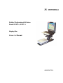
Mobile Workstation 800 Series
Model F5207A, F5217A
Display Box
Owner’s Manual
6802976C75-O
2
MW800 Owner’s Manual
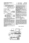
COMPUTER SOFTWARE COPYRIGHTS
The Motorola products described in this instruction manual may include copyrighted
Motorola computer programs stored in semiconductor memories or other media. Laws in
the United States and other countries preserve for Motorola certain exclusive rights for
copyrighted computer programs, including the exclusive right to copy or reproduce in
any form the copyrighted computer program. Accordingly, any copyrighted Motorola
computer programs contained in the Motorola products described in this instruction
manual may not be copied or reproduced in any manner without the express written
permission of Motorola. Furthermore, the purchase of Motorola products shall not be
deemed to grant either directly or by implication, estoppel or otherwise, any license under
the copyrights, patents or patent applications of Motorola, except for the normal nonexclusive, royalty free license to use that arises by operation of law in the sale of a
product.
COPYRIGHT
Copyright © 2003-2004 Motorola Inc. All rights reserved. No part of this manual may be
transmitted, stored in a retrieval system, or translated into any language or computer
language, in any form or by any means, without the prior written permission of Motorola
Inc.
TRADEMARKS
• Motorola and the Stylized M logo are registered trademarks of Motorola Inc.
• Microsoft, Windows and the Windows logo are registered trademarks of Microsoft
Corporation.
• The Bluetooth trademarks are owned by their proprietor and used by Motorola, Inc.
under license in the U.S. and other countries.
All other product or service names are the property of their respective owners.
WARRANTY DISCLAIMER
Motorola may add, delete, change, or withdraw, in whole or in part, this document or
software described in this document at any time and without notice. Such document
modifications will be incorporated in new releases of this document on an intermittent
basis. Motorola disclaims any responsibility for labor or material cost involved by
persons outside the company as a result of using this document.
3
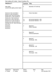
TABLE OF CONTENTS
Using this Manual .......................................................................................................................................... 5
Who Should Use this Manual .................................................................................................................... 5
Manual Introduction .................................................................................................................................. 5
Related Manuals ........................................................................................................................................ 5
Conventions Used in This Manual............................................................................................................. 6
Section 1:
Getting Started ................................................................................................................... 7
What is the Display Box? .......................................................................................................................... 7
Section 2:
Basic Operations ................................................................................................................ 8
Power On ................................................................................................................................................... 8
Normal operation .................................................................................................................................. 8
Extreme Temperature Conditions ......................................................................................................... 8
Discharged Vehicle Battery .................................................................................................................. 8
Turn Off..................................................................................................................................................... 9
Normal Operation ................................................................................................................................. 9
Extreme Shut Down.............................................................................................................................10
Power Management ..................................................................................................................................10
Standby ................................................................................................................................................10
Resume ................................................................................................................................................10
Volume Adjustment..................................................................................................................................11
Brightness Adjustment..............................................................................................................................11
Emergency key operation .........................................................................................................................11
Function key operation .............................................................................................................................12
Touch screen Calibration ..........................................................................................................................13
Section 3:
Display Configuration.......................................................................................................14
Display Configuration Parameters............................................................................................................14
Display Configuration Change .................................................................................................................16
Maintenance Programming Software...................................................................................................16
How to Modify Configuration Parameters...........................................................................................16
Section 5:
Software/Firmware Upgrade.............................................................................................19
Description/Tutorial..................................................................................................................................19
Display Firmware Update.........................................................................................................................19
Automatic Firmware Update................................................................................................................20
Manual Firmware Update ....................................................................................................................20
Display Utilities Update ...........................................................................................................................22
Automatic Display Utilities Update .....................................................................................................22
Manual Display Utilities Update..........................................................................................................22
Section 7:
Getting Assistance from Motorola....................................................................................23
Appendix A:
Safety Instructions........................................................................................................24
Appendix B:
Warranty Information...................................................................................................26
Appendix C:
FCC Information ..........................................................................................................29
Appendix D:
Display Factory Setup ..................................................................................................30
Appendix E:
Troubleshooting ...........................................................................................................31
Appendix F:
Acronyms and Abbreviations.......................................................................................33
TABLE OF FIGURES
Figure 1. ExtraKey Configuration .................................................................................................................12
Figure 2. Calibration Window .......................................................................................................................13
Figure 3. Main MPS Window........................................................................................................................17
Figure 4. Codeplug Editor .............................................................................................................................17
Figure 5. Support Kit, Main Menu ................................................................................................................19
Figure 6. EC Loader Setup ............................................................................................................................21
Figure 7. EC Loader Programming ...............................................................................................................21
4
MW800 Owner’s Manual
Figure 8. Successful Programming................................................................................................................22
Table 1. Error Messages About Abnormal Conditions..................................................................................31
Table 2. Failure Indications ...........................................................................................................................32
Table 3. Failures Without Notification..........................................................................................................32
5
Using this Manual
Before using this manual and products it describes, be sure to read the Safety
instructions in Appendix A, the Warranty information in Appendix B and the FCC
information in Appendix C.
Who Should Use this Manual
This manual is intended for staff who operate the Mobile Workstation 800 (MW800)
and need to configure, upgrade or maintain its display box. This manual assumes the
reader is familiar with the MW800 and basic Windows operations. If this is not the
case, be sure to read the MW800 User’s Guide and documentation that came with
your version of Windows.
For documentation of supplied software applications, refer to the help file attached to
each application.
Manual Introduction
The MW800 mobile workstation consists of three separate interconnected
components: CPU box, Display and Keyboard. This manual only deals with the
display box, which is also referred to as either device or Display in this manual. This
manual is organized as follows:
•
•
•
•
•
Section 1 provides an overview.
Section 2 provides a description of basic operations.
Section 3 describes various parameters that define Display configuration
when you turn on your computer.
Section 4 explains how to upgrade display firmware.
Section 5 describes how to get assistance from Motorola.
The Appendixes contain:
•
•
•
•
•
•
Appendix A:
Appendix B:
Appendix C:
Appendix D:
Appendix E:
Appendix F:
Safety instructions
Warranty information
FCC information
Display factory setup
Troubleshooting information
Acronyms and Abbreviations
Related Manuals
This manual describes the MW800 display box and provides basic operating
instructions. Please, note that although this manual refers to hardware and software
6
MW800 Owner’s Manual
components supplied with this product, it does not provide full component
description. For additional information refer to the following documents:
•
•
•
Mobile Workstation 800 Series, User’s Guide
Mobile Workstation 800 Series, CPU Owner’s Manual
Mobile Workstation 800 Series, Installation Manual
- 6802976C65
- 6802976C60
- 6802967C20
For documentation of software applications supplied with this product, refer to the
help file attached to each application. This manual is designed to supplement the online help or on-line context-sensitive help installed with every software component.
Please review this information to ensure proper use of the product.
Also, if you need to be able to change the configuration of your device, refer to
•
Mobile Workstation 800 Series,
Maintenance Programming Software, User’s Manual
- 6802976C70
For additional information visit the MW800 home page http://www.motorola.com.
Conventions Used in This Manual
Throughout this publication, you will notice the use of danger and caution marks.
These notations are used to emphasize that safety hazards exist, and care must be
taken. Do not proceed beyond a DANGER or CAUTION until the indicated
conditions are fully understood and met.
The following conventions are used throughout this manual:
Italics
Used for emphasis and for new terms.
Bold
Used to indicate keyboard keys or application buttons.
Program ->
Motorola ->
MW800 CPU->
CPU Manager
Used to designate the location and name of a menu function.
For example, Program -> Motorola -> MW800 CPU->
CPU Manager launch CPU Manager program.
Note:
Indicates an operational procedure, practice, or condition to
which you should pay special attention.
CAUTION:
Alerts you of conditions, which can result in loss or
corruption of data, or damage to device.
DANGER:
Indicates a potentially hazardous situation, which, if not
avoided, may result in injury. It may also be used to alert
against unsafe practices and property-damage-only accident
hazards.
7
Section 1:
Getting Started
What is the Display Box?
The MW 800 offers three choices of rugged display:
•
12.1’ XGA Display with touch screen
The 12.1” XGA display, with a resolution of 1024 x 768 pixels. The screen
contains 1200 NIT (1200 Cd/m2) high-brightness backlighting, ensuring glarefree viewing under virtually any lighting conditions.
•
12.1’ SVGA Display with touch screen
The 12.1” SVGA display, with a resolution of 800 x 600 pixels. The screen
contains 350 NIT (350 Cd/m2) standard brightness backlighting.
•
8.4’ SVGA Display
The 8.4” SVGA display, with a resolution of 800 x 600 pixels. The screen
contains 350 NIT (350 Cd/m2) standard brightness backlighting.
All displays are equipped with a touch screen (8-wire active matrix) that can be
activated with either a gloved finger or a stylus pen. All displays use TFT screen
technology. The screens are made of a tempered glass and are covered by a
protective film to prevent the glass from shattering in the event of breakage.
The 12.1” screens use built-in Bluetooth technology (optional) to provide wireless
connection to personal peripherals such as headset, mouse, printer etc. Two USB 1.1
ports provide connectivity to external USB devices.
This manual refers to all display options.
8
MW800 Owner’s Manual
Section 2:
Basic Operations
This section describes the following operations:
•
•
•
•
•
•
•
•
Power On
Power Off
Standby
Resume
Volume Adjustment
Brightness Adjustment
Emergency key operation
Function key operation
Power On
This chapter describes methods to power on he display in normal and extreme
conditions.
NOTE: Prior to power on the display, be aware, that the main power switch on the
rear CPU panel is in the ON position.
Normal operation
The display box can be turned off either from the CPU box or from the power button
located on the right display’s side.
•
If the display is configured to be powered on USB 5V presence (see section
3, Power up preferences setting is USB 5V Presence), the device will be
powered on as soon as the when USB 5V appears.
•
If the display is configured to be powered on by the power button, (see
section 3, Power up preferences setting is POWER BUTTON), the device
will be powered on when display’s or CPU power button is pressed.
You can select any of above options or use their combination.
Extreme Temperature Conditions
The device powers up only when the temperature is within the operating range.
When the ambient temperature is beyond the operational range, the display will
indicate about operational failure and will not power on.
Discharged Vehicle Battery
If the power source is 13.8VDC (see Power source parameter in section 3), the
device will normally power up when the voltage level exceeds 10.3VDC.
9
If the power source is 9VDC (see Power source parameter in section 3), the device
will normally power up when the voltage level exceeds 9VDC.
Turn Off
This chapter describes methods to power off the display box and the MW800 in
normal and extreme conditions.
Normal Operation
The display box can be turned off either from the CPU box or from the power button
located on the right display’s side.
•
If the display is configured to be powered off upon receiving CPU power off
request (see section 3, Power off preferences setting is CPU REQUEST),
the device will automatically shut itself down when the CPU issues power off
request.
•
If the display is configured to be turned off when USB 5V disappears (see
section 3, Power off preferences setting is USB 5V Absence), the device
will automatically shut itself down as soon as the CPU is powered off.
•
If the display is configured to be turned off by the power button, (see section
3, Power off preferences setting is POWER BUTTON), the device will be
turned off when display’s power button is pressed.
You can select any of above options or use their combination.
If powering off by Power Button is selected, the display will turn itself off
immediately after pressing of the Power Button, not waiting for the end of the CPU
shut down process.
This immediate turning the display off may force the CPU to shut down depending
on the Power off USB command to CPU parameter (see Section 3). If your
intention is to turn off the CPU when display’s power button is pressed, setting of
this parameter should be ENABLE. If it’s not your intention, disable sending of
Power Off notification to the CPU - it will prevent the CPU from shutting down.
TIP: If you want to disable CPU shut down when you press the Power button, set the
following:
•
•
•
•
Power off USB command to CPU = DISABLE.
Critical turn off = DISABLE.
Power off on CPU REQUEST = NO.
Power off from Power Button = NO.
10
MW800 Owner’s Manual
If the system does not respond, you can turn the device off by pressing and holding
the display power button for 6 seconds or more. To permit this option, Critical turn
off parameter (see Section 3) setting should be ENABLE. Be aware, this hardware
power off may damage your hard disk.
Extreme Shut Down
Some extreme events might cause the device to power off. These are ambient
temperature below the low or above the high operating limit or discharged car
battery.
•
Internal temperature is beyond the operational limit.
If during operation the internal temperature goes out of the low operational
limits, the display eventually powers off.
•
Vehicle battery is discharged.
If, during normal operation, the battery voltage drops below 10.5VDC the
display will provide Low Battery indication (the power indicator blinks
yellow). If the voltage continues to drop, the device automatically powers off
at 8.5VDC.
•
Drops in car battery voltage.
If battery voltage drops below the 8.8V limit for 20 seconds or more, the
device will execute critical shut off and power itself off.
Power Management
This chapter describes how to enter the CPU into low-power mode (standby) and
resume normal operating mode.
Standby
The display can enter the CPU into low-power state by pressing the Standby button
on the right display’s side.
One more way to move the CPU into low-power mode is to configure the Power
button to enter the CPU into a low-power state. For details about this option, refer to
the help file attached to Power Options (Start -> Settings -> Control Panel ->
Power Options).
Resume
The display can resume the CPU using the following methods:
•
A contact to the touch panel of the MW800 display
11
•
•
•
Pressing the Emergency key of the MW800 display
Pressing the Function key of the MW800 display
Power button (if configured)
A contact to the touch panel, pressing the Emergency key or function key can resume
the CPU out of standby if its setting specifies the operating system to come out of a
low power state when there is USB activity. To enable this feature, Allow this
device to bring the computer out of standby option (Power Management tab in
Properties) should be selected. For details about this option, refer to the help file
attached to the Properties of the device.
Default setting of the operating system allows resume from the touch panel,
emergency and function keys.
Pressing of the Power button will bring the computer out of standby if its setting
specifies the operating system to come out of a low power state when you press the
Power button. For details about this option, refer to the help file attached to Power
Options (Start -> Settings -> Control Panel -> Power Options).
Default setting of the operating system does not allow resume from the power
button.
Volume Adjustment
Two control buttons for volume adjustment (Volume Up and Volume Down) in
conjunction with software Volume Control application allow setting of volume level.
Volume window allows color modifications and pops-up on every volume change. If
your display unit includes BlueTooth component, this application also allows
commutation of audio stream to the BlueTooth device.
Brightness Adjustment
Two control buttons for brightness adjustment (Brightness Up and Brightness
Down) allow setting of brightness level. The display allows limiting relative
brightness level, which cannot be exceeded by this display. See the Maximum
Brightness parameter in section 3.
Emergency key operation
The display is equipped with the large bright-red emergency button. When the
emergency button is pressed, the display provides high-priority data event to the
CPU box operating system. That intends for a customer software emergency
applications that may hook and process this event.
12
MW800 Owner’s Manual
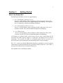
Function key operation
The display has a number of function keys (12.1’ – eight, 8.4’ – six) across the
bottom of the display that can be assigned different functions under mobile
application software control that can be configured for other Windows applications.
The Extrakey application, which is a part of the MW800 software, allows the
function key to operate like the standard keyboard hotkey, launch any application
(like Notepad or Calculator) or blank the display. ExtraKey application's desktop
toolbar is situated on one of the edges of the screen (default - the bottom edge).
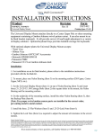
You can customize the Extrakey using Configuration window, which can be run
either from the Control Panel, or by left-clicking the ExtraKey tray icon and
choosing Configuration in the pop-up menu.
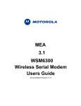
Each display function key can be mapped either to hot key (such as Ctrl + X, F1
etc.), to file (as a shortcut), or to the display switch:
Figure 1. ExtraKey Configuration
How to set a shortcut to the hot key
•
•
•
Choose Hot Key in the Map to drop-list.
Move cursor to Press new hotkey field and right-click once to activate it.
Press key you want on the keyboard. Field Name defines how the Extrakey
Bar button will be named (this is optional).
How to set a shortcut to the application
•
•
Choose File in the Map to drop-list.
Enter full path to file you want to open or click the button to browse. Field
Name defines how the Extrakey Bar button will be named (this is optional).
13
How to set a shortcut to the display switch
•
•
Choose Display switch in the Map to drop-list.
Field Name defines how the Extrakey Bar button will be named (this is
optional).
The ExtraKey Application on-line help provides context-sensitive information.
Please, take the time to read this information in order to operate the device correctly.
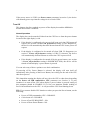
Touch screen Calibration
Sometimes there is a need to calibrate the touch panel attached to the display
monitor, i.e. to adjust the pushed position of the panel and its display position of the
monitor. Even if the touch panel has same dimensions as the display monitor, there
may be minor variations in between corresponding data points because of resistance
variance of each panel.
When you use touch panel module for the first time, or, when there is discrepancy
between the pushed and displayed positions, then calibration is required. This needs
to be done only once, and then, calibration data is stored. The CPU will
automatically calculate the touched position on display monitor.
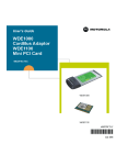
This adjustment may be executed with the MW800 Display Calibration Tool.
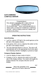
Figure 2. Calibration Window
This utility performs the following:
•
Calibrate Device
•
Reset Device
•
Simulate Calibration
saving calibration
Test
Double-Click Setting
•
•
Calibrates the touch screen and saves calibration
data
Nullifies calibration parameters in the MW800
display codeplug
Simulates calibration of the touch screen without
Briefly tests of the touch screen after calibration
Calibrates the double-click on the touch screen
14
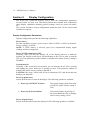
MW800 Owner’s Manual
Section 3:
Display Configuration
The device has a protected memory area to store the configuration parameters
accessed when you turn it on. That binary-format data contains basic information
about display capabilities including general settings, power-up, power-off modes,
etc.
This section describes various configuration parameters that can be selected and
modified as required
Display Configuration Parameters
Display configuration provides the following capabilities:
Power source
Provides capability to select a power source: either 13.8VDC or 9VDC car batteries.
Factory setting is 13.8VDC.
NOTE: if 9VDC battery is selected, power loss compensation during engine
cranking will be not supported.
Power off USB command to CPU
Normally, when you turn the display off, or the display discovers a hardware
problem, the Display sends Power Off notification to the CPU in order to turn the
CPU off. This parameter provides enables or disables this feature. Factory setting is
ENABLE.
Critical turn off
Normally, if the system does not respond, you can turn the device off by pressing
and holding the power button for 6 seconds or more. This parameter enables or
disables this feature. Factory setting is ENABLE.
CAUTION: Be aware, critical turn off forces immediate CPU shut down and may
damage your hard disk.
Power up preferences
Selects desired source to turn on the display. The following options are available:
•
Power Up on USB 5V Presence
Turn on the display on the front edge
of USB 5V signal. Factory setting is
YES.
•
Power Up by Power Button
Turn on the display on pressing of
the Power Button on CPU or Display
units. Factory setting is YES.
Power off preferences
Selects desired method to turn the display off. The following options are available:
15
•
Power off on USB 5V Absence
Turn the display off as soon as the
CPU unit is powered off. Factory
setting is NO.
•
Power off on CPU REQUEST
Turn the display off when CPU
power-off request is received.
Factory setting is YES.
•
Power off by Power Button
Turn the display off as soon as the
display Power Button is pressed.
Factory setting is YES.
Idle Time-out when CPU is not powered
This parameter provides several options to power on the display while the CPU is
off. The following options are available:
•
•
NEVER
10 sec
•
FOREVER
Does not power on if the CPU is off.
Power on and wait up to 10 seconds for the CPU trigger
(USB 5V presence). If 10-second time-out is expired and
the CPU trigger did not occur, the display will power itself
off.
Power on and wait for the CPU power up without any time
limitation.
Factory setting is 10 seconds.
Bluetooth Device on Power Up
Indicates presence of the Bluetooth hardware. This field is set when BT hardware
exists and supports audio; otherwise it is reset. Factory setting is ON.
Brightness Threshold
Shows relative brightness threshold for LCD temperature control. This is factory
setting.
Brightness Slope
Shows the slope of brightness decreasing for the LCD temperature control. This is
factory setting.
Maximum Brightness
Defines relative brightness level, which cannot be exceeded by this display. The
parameter can be changed in the range from 0 to 63; factory setting is 63.
Number of Displays
Defines connection of one or two displays to the CPU. Factory setting is ONE.
16
MW800 Owner’s Manual
Display Port
When one display is connected to the CPU, this parameter defines what CPU port the
display is connected to. Factory setting is DISPLAY 1.
BT MAC Address
Shows unique Bluetooth media access control address. This is read-only field.
Board Number
Shows internal identification of display main-board. This is read-only field.
Serial Number
Shows display serial number. This is read-only field.
NOTE: Understand that the Display configuration should be compatible with the
CPU and vice versa.
Refer to Appendix H for factory setting of the display configuration parameters.
Display Configuration Change
This chapter describes software tool and the most common method to change the
display configuration.
Maintenance Programming Software
The Maintenance Programming Software enables modification of the configuration
that starts when you turn the display on. Use the MPS context-sensitive on-line help
information for assisting in configuring the device.
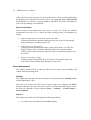
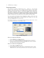
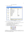
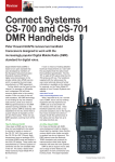
How to Modify Configuration Parameters
To modify the configuration parameters perform the following:
•
Double-click on the MPS icon; main MPS window appears on the screen.
17
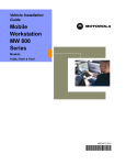
Figure 3. Main MPS Window
•
Click on Codeplug Editor
Figure 4. Codeplug Editor
To modify configuration parameters use the MPS tool as the following:
•
•
•
•
•
Click on Read from Display to read the codeplug parameters. If your device
is successfully read, you will see CPU parameters.
Click on Save to file to backup the original codeplug data.
Modify a parameter per your selection.
Click on Write to Display to program the device.
If the device is successfully programmed, the following message appears.
CAUTION: Incorrect configuration can make the device unworkable. Please, make
sure to acquire the appropriate codeplug. Always make a backup copy in case you
have made a mistake during the update.
18
MW800 Owner’s Manual
Note: For details refer to Maintenance Programming Software User’s Manual.
19
Section 4:
Software/Firmware Upgrade
Use the MW800 Support CD-ROM part No. FVN5413A kit when you need to install
or update unique software and firmware components.
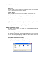
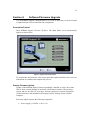
Description/Tutorial
Insert MW800 Support CD into CD drive. The Main Menu screen automatically
appears as shown next:
Figure 5. Support Kit, Main Menu
To perform the desired action, click on the particular option and follow the on-screen
instructions to continue and complete the process.
Display Firmware Update
Update of the MW800 display firmware (both 12.1’ and 8.4’ as well) can be done
ONLY from external desktop or notebook with Windows 2000 or XP operating
system and one free RS-232 serial port. It needs connection of special equipment
(Connection Box) and installation of Display Utilities Package on the external
computer.
Firmware update requires the following equipment:
•
Power supply (13.8VDC ± 20%, 5A)
20
MW800 Owner’s Manual
•
•
•
•
Power supply cable HKN4192B
Connection box FLN3218
Serial cable 308756V14.
Cable adaptor
Perform the following steps:
•
•
•
•
•
Turn off the Main Power Switch (on the rear of the CPU box) when
connecting the cables.
Connect the power supply to the display.
Attach the connection box to free RS-232 port on your computer via Serial
Port cable (RS-232 9-pin Female to Male straight Serial Port cable
308756V14).
Detach the display from the CPU box and attach Display-to-CPU cable to the
Connection box.
Put the MW800 display into the ‘Monitor’ mode as the following: press the
OSD button, then Power On button and wait until the blue LED on the
MW800 display panel is on.
Automatic Firmware Update
Insert the Support Kit into the CD-ROM drive and click on the Firmware Updates
and then 12’1’ Display (or 8.4’ Display) button. The MW800 Support kit
automatically replaces the display firmware.
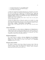
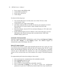
Manual Firmware Update
For manual CPU firmware update launch the MPS and then the EC Loader tool. This
tool provides ability to program a S-Record file to EC memory flash. The EC Loader
allows downloading the firmware into the device only if the firmware is compatible
with the type of embedded CPU controller. In a case of incompatibility the loader
reports an error and prevents users from mistakes like trying to download improper
file.
Set programming and connection settings as shown next:
•
•
•
•
•
Select serial port for communication with embedded controller.
Select External connection type.
Select Display firmware target.
Select a file to be downloaded into embedded controller.
Select Overwrite Codeplug if you want to replace the configuration
parameters in your device with factory default. Otherwise, keep it unselected.
21
Figure 6. EC Loader Setup
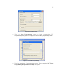
•
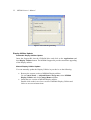
Click on Start Programming button to begin programming. EC
Programming dialog appears; the progress bar will show programming status.
Figure 7. EC Loader Programming
•
Wait for completion of programming process. When completed EC Flash
Programming has passed successfully will appear.
22
MW800 Owner’s Manual
Figure 8. Successful Programming
Display Utilities Update
Automatic Display Utilities Update
Insert the Support Kit into the CD-ROM drive and click on the Applications and
then Display Utilities button. The MW800 Support kit provides automatic upgrading
of the Display utilities.
Manual Display Utilities Update
You can manually update the Display Utilities in your device as the following:
•
•
Remove the current version of MW800 Display utilities.
Go to Control Panel -> Add and Remove Programs, select MW800
Display Utilities and click Change/Remove button.
Install the new version of MW800 Display utilities.
Double click on the icon of new version of MW800 Display Utilities and
follow to on-screen instructions.
23
Section 5:
Getting Assistance from Motorola
For your convenience, Motorola Web site provides up-to-date information about
MW800 products.
The address for MW800 home page is http://mw800.motorola.com.
This site includes general information about the device; here you can find answers to
most of your questions or problems on operating your device. Also, you could:
•
•
•
Obtain updates from Motorola
Update embedded firmware for your computer
Get the latest device drivers
24
MW800 Owner’s Manual
Appendix A: Safety Instructions
DANGER:
Reduce the risk of fire or electric shock by following basic safety instructions:
• Do not use your device during electrical storms.
• Do not connect or disconnect cables while you device is turned on.
• Protect your device from liquids. Keep your device away from water.
• Do not use any power cord where input or output pins show signs of corrosion
or overheating.
• Be sure that all power cord connections are securely plugged into receptions.
• Never wrap a power cord.
• Always route a power cord and communication cables so they will not be
damaged.
DANGER:
To avoid shock hazard, disconnect power cord and all communication cables when
you open the covers of your device.
DANGER:
Electric current from power and communication cables is hazardous. To prevent
shock hazard follow the installation recommended in the Installation Manual.
DANGER:
An improperly grounded device is hazardous. To prevent shock hazard follow the
installation recommended in the Installation Manual.
CAUTION:
The device dissipates some heat during normal operation. When the device is
operating, do not leave it in contact with any part of your body for an extended
period of time – it could cause a sense of discomfort.
CAUTION:
The device generates heat when on. Never block or cover ventilations slots and fans.
CAUTION:
The device is sensitive to uncontrolled shut down. Never turn off the device by
turning off the power supply or by disconnection of the power cable.
CAUTION:
Hard drive performance and lifetime could be shortened if the device is not used for
long period of time. Do not leave the device unused for more than 3 months.
CAUTION:
25
If you have added or upgraded a memory card or Mini PCI card or any other
component, do not use your device until you have closed the covers. Never use the
device when cover(s) is open.
CAUTION:
CMOS battery can degrade when your device is not used for long period of time.
Leaving a battery unused in a discharged state could shorten a lifetime of the battery.
CAUTION:
The device automatically shuts down then the internal temperature exceeds the upper
limit of the valid range. Never turn the device on until it cools down.
CAUTION:
Avoid inserting of any card into computer slots at an angle – it could damage
connectors in the device.
CAUTION: Normally, if the system does not respond, you can turn the device off
by pressing and holding the power button for 6 seconds or more. Be aware, this
hardware power off may damage the hard disk.
CAUTION: Do not insert or remove card when the MW800 is in Suspend mode.
Before you insert or remove a card, make sure that you exit all software applications
that access the card.
CAUTION: When replacing a device, verify that it is hot swappable. Otherwise,
turn off your device prior to replacement.
CAUTION: Wrong configuration can make your device unworkable. Please, make
sure to acquire the appropriate codeplug. Always make a backup copy in case you
have made a mistake during the update.
26
MW800 Owner’s Manual
Appendix B: Warranty Information
EPS – 34440- B
This warranty applies within the fifty (50) United States, the District of Columbia and
Canada.
LIMITED WARRANTY
MOTOROLA COMMUNICATION PRODUCTS
If the affected product is being purchased pursuant to a written Communications System
Agreement signed by Motorola, the warranty contained in that written agreement will
apply. Otherwise, the following warranty applies.
I. WHAT THIS WARRANTY COVERS AND FOR HOW LONG:
Motorola Inc. or, if applicable, Motorola Canada Limited ("Motorola") warrants the
Motorola manufactured radio communications product, including original equipment
crystal devices and channel elements ("Product"), against material defects in material and
workmanship under normal use and service for a period of One (1) Year from the date of
shipment. Motorola, at its option, will at no charge either repair the Product (with new or
reconditioned parts), replace it with the same or equivalent Product (using new or
reconditioned Product), or refund the purchase price of the Product during the warranty
period provided purchaser notifies Motorola according to the terms of this warranty.
Repaired or replaced Product is warranted for the balance of the original applicable
warranty period. All replaced parts of the Product shall become the property of Motorola.
This express limited warranty is extended by Motorola to the original end user purchaser
purchasing the Product for purposes of leasing or for commercial, industrial, or
governmental use only, and is not assignable or transferable to any other party. This is the
complete warranty for the Product manufactured by Motorola. Motorola assumes no
obligations or liability for additions or modifications to this warranty unless made in
writing and signed by an officer of Motorola.
Unless made in a separate written agreement between Motorola and the original end user
purchaser, Motorola does not warrant the installation, maintenance or service of the
Product. Motorola cannot be responsible in any way for any ancillary equipment not
furnished by Motorola, which is attached to or used in connection with the Product, or for
operation of the Product with any ancillary equipment, and all such equipment is
expressly excluded from this warranty. Because each system, which may use the Product,
is unique, Motorola disclaims liability for range, coverage, or operation of the system as a
whole under this warranty.
II. GENERAL PROVISIONS:
This warranty sets forth the full extent of Motorola’s responsibilities regarding the
Product. Repair, replacement or refund of the purchase price, at Motorola’s option, is the
exclusive remedy. THIS WARRANTY IS GIVEN IN LIEU OF ALL OTHER EXPRESS
WARRANTIES. MOTOROLA DISCLAIMS ALL OTHER WARRANTIES OR
CONDITIONS, EXPRESS OR IMPLIED, INCLUDING THE IMPLIED
WARRANTIES OR CONDITIONS OF MERCHANTABILITY AND FITNESS FOR A
PARTICULAR PURPOSE. IN NO EVENT SHALL MOTOROLA BE LIABLE FOR
27
DAMAGES IN EXCESS OF THE PURCHASE PRICE OF THE PRODUCT, FOR
ANY LOSS OF USE, LOSS OF TIME, INCONVENIENCE, COMMERCIAL LOSS,
LOST PROFITS OR SAVINGS OR OTHER INCIDENTAL, SPECIAL, INDIRECT OR
CONSEQUENTIAL DAMAGES ARISING OUT OF THE USE OR INABILITY TO
USE SUCH PRODUCT, TO THE FULL EXTENT SUCH MAY BE DISCLAIMED BY
LAW.
III. HOW TO GET WARRANTY SERVICE:
Purchaser must notify Motorola’s representative or call Motorola’s Customer Response
Center at 1-800-247-2346 within the applicable warranty period for information
regarding warranty service.
IV. WHAT THIS WARRANTY DOES NOT COVER:
A) Defects or damage resulting from use of the Product in other than its normal and
customary manner.
B) Defects or damage from misuse, accident, water, or neglect.
C) Defects or damage from improper testing, operation, maintenance, installation,
alteration, modification, or adjustment.
D) Breakage or damage to antennas unless caused directly by defects in material
workmanship.
E) A Product subjected to unauthorized Product modifications, disassemblies or repairs
(including, without limitation, the addition to the Product of non-Motorola supplied
equipment) which adversely affect performance of the Product or interfere with
Motorola’s normal warranty inspection and testing of the Product to verify any warranty
claim.
F) Product, which has had the serial number removed or made illegible.
G) Batteries (they carry their own separate limited warranty).
H) Freight costs to the repair depot.
I) A Product, which, due to illegal or unauthorized alteration of the software/firmware in
the Product, does not function in accordance with Motorola’s published specifications or
with the FCC type acceptance labeling in effect for the Product at the time the Product
was initially distributed from Motorola.
J) Scratches or other cosmetic damage to Product surfaces that do not affect the operation
of the Product.
K) That the software in the Product will meet the purchaser’s requirements or that the
operation of the software will be uninterrupted or error-free.
L) Normal and customary wear and tear.
M) Non-Motorola manufactured equipment unless bearing a Motorola Part Number in
the form of an alphanumeric number (i.e., TDE6030B).
V. GOVERNING LAW
In the case of a Product sold in the United States and Canada, this Warranty is governed
by the laws of the State of Illinois and the Province of Ontario, respectively.
VI. PATENT AND SOFTWARE PROVISIONS:
Motorola will defend, at its own expense, any suit brought against the end user purchaser
to the extent that it is based on a claim that the Product or its parts infringe a United
28
MW800 Owner’s Manual
States patent, and Motorola will pay those costs and damages finally awarded against the
end user purchaser in any such suit which are attributable to any such claim, but such
defense and payments are conditioned on the following:
A) that Motorola will be notified promptly in writing by such purchaser of any notice of
such claim;
B) that Motorola will have sole control of the defense of such suit and all negotiations for
its settlement or compromise; and
C) should the Product or its parts become, or in Motorola's opinion be likely to become,
the subject of a claim of infringement of a United States patent, that such purchaser will
permit Motorola, at its option and expense, either to procure for such purchaser the right
to continue using the Product or its parts or to replace or modify the same so that it
becomes non-infringing or to grant such purchaser a credit for the Product or its parts as
depreciated and accept its return. The depreciation will be an equal amount per year over
the lifetime of the Product or its parts as established by Motorola. Motorola will have no
liability with respect to any claim of patent infringement which is based upon the
combination of the Product or its parts furnished hereunder with software, apparatus or
devices not furnished by Motorola, nor will Motorola have any liability for the use of
ancillary equipment or software not furnished by Motorola which is attached to or used in
connection with the Product. The foregoing states the entire liability of Motorola with
respect to infringement of patents by the Product or any of its parts thereof.
Laws in the United States and other countries preserve for Motorola certain exclusive
rights for copyrighted Motorola software such as the exclusive rights to reproduce in
copies and distribute copies of such Motorola software. Motorola software may be used
only in the Product in which the software was originally embodied and such software in
such Product may not be replaced, copied, distributed, modified in any way, or used to
produce any derivative thereof. No other use including, without limitation, alteration,
modification, reproduction, distribution, or reverse engineering of such Motorola
software or exercise of rights in such Motorola software is permitted. No license is
granted by implication, estoppel or otherwise under Motorola patent rights or copyrights.
29
Appendix C: FCC Information
CAUTION: Changes or modifications made in the CPU box or Display, not expressly
approved by Motorola, will void the user's authority to operate the equipment
EPS – 48759 – O
FCC INTERFERENCE WARNING
The FCC requires that manuals pertaining to Class A and Class B computing devices
must contain warnings about possible interference with local residential radio and TV
reception. This warning reads as follows:
NOTE: This equipment has been tested and found to comply with limits for a Class B
digital device, pursuant to Part 90 of the FCC Rules. These limits are designed to provide
reasonable protection against harmful interference when the equipment is operated in a
commercial or residential environment. This equipment generates, uses, and can radiate
radio frequency energy and, if not installed and used in accordance with the instruction
manual, may cause harmful interference to radio communications.
For detailed product safety and RF exposure for mobile stations with two-way radios
installed in vehicles, refer to Electromagnetic Emission (EME) safety leaflet, Motorola
publication number 68P02967C16.
FCC Compliance Notice
The FCC requires that manuals pertaining to Class A and Class B computing devices
must contain warnings about possible interference with local residential radio and TV
reception. This warning reads as follows:
NOTE: This equipment has been tested and found to comply with limits for a Class B
digital device, pursuant to Part 90 of the FCC Rules. These limits are designed to provide
reasonable protection against harmful interference when the equipment is operated in a
commercial or residential environment. This equipment generates, uses, and can radiate
radio frequency energy and, if not installed and used in accordance with the instruction
manual, may cause harmful interference to radio communications.
This device complies with Part 90 of the FCC Rules. Operation is subject to the following
two conditions:
(1) This device may not cause harmful interference.
(2) This device must accept any interference received, including interference that may
cause undesired operation.
For detailed product safety and RF exposure for mobile workstations, with two-way
radios, installed in vehicles, refer to Electromagnetic Emission (EME) safety leaflet,
Motorola publication number 68P02967C16.
30
MW800 Owner’s Manual
Appendix D: Display Factory Setup
Power source
Power off USB command to CPU
Critical turn off
Power Up on USB 5V Presence
Power Up from Power Button
Power off on USB 5V Absence
Power off on CPU REQUEST
Power Off from Power Button
Idle Time-out when CPU is not powered
Bluetooth Device on Power Up
Brightness Threshold
Brightness Slope
Maximum Brightness
Number of Displays
Display Port
BT MAC Address
Board Number
Serial Number
- 13.8V
- ENABLE.
- ENABLE
- YES
- YES
- NO
- YES
- YES
- 10 seconds
- ON
- Factory setting
- Factory setting
- 63
- ONE
- DISPLAY 1
- Factory setting
- Factory setting
- Factory setting
31
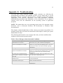
Appendix E: Troubleshooting
You can solve many problems without outside assistance by following the
troubleshooting procedures that MW800 provides in the online help or in the
documents that are provided with the device, operating system and software
applications. Most software applications come with description containing
troubleshooting procedures and explanation of error information. If you suspect a
software issue, refer the information for the operating system or application
programs.
NOTE: This manual does not cover operating system issues. For operation system
directions, refer to Microsoft Windows XP Professional or Windows 2000
documentation.
This chapter contains helpful hints to follow when you encounter any problem. If a
problem persists after you follow the instructions in this chapter, contact your system
administrator for help.
The following table describes error messages that warn you about conditions that
might prevent the normal operation mode.
Table 1. Error Messages About Abnormal Conditions
Message
Vehicle Battery is Low. The system
will shutdown in 3 minutes.
MW800 CPU temperature is high. The
system will shutdown in 3 minutes.
Warning condition is over
MW800 CPU temperature is low. The
system will shutdown in 3 minutes.
PC Card error was detected. Please
remove the PC Card device and than
press OK.
MW800 hard drive heater may be
malfunctioned.
Over current is detected in device
connected to Firewire port.
MW800 CPU Fan Failure.
Do the following
The car battery voltage is below of the low operational
limit. Please save your work before shutting down
The internal temperature is higher than the valid limit.
Please save your work before shutting down. Never turn
on the device until it cools down to normal operating
temperature.
Cancel Warning
The internal temperature is below of the valid limit.
Please save your work before shutting down. Never turn
on the device until it heats up to normal operating
temperature.
Card Bus over-current is discovered. Please remove the
PC Card device and than press OK
Heater over-current is discovered. Please, contact your
system administrator.
The MW800 cannot work with this Firewire device.
Please, disconnect the device.
This is Fan alarm. Please, contact your system
administrator.
32
MW800 Owner’s Manual
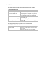
The MW800 display provides the following indication about a failure condition.
Table 2. Failure Indications
Indication
Power LED is off
Power LED is steady yellow
Temperature LED blinks red
Temperature LED blinks yellow
Communication LED is steady blue
Communication LED is steady yellow
Communication LED is steady purple
Link LED is yellow & green
What’s the problem
Check the plug and the power cord.
Vehicle battery is low (9.4 to 10.3 VDC) during
workstation power up.
Display temperature is extremely high during power on
Display temperature is extremely low during operation.
CPU box to display USB power problem, or display in
programming mode. Check the plugs and CPU cable.
CPU box fails to communicate with display. Check the
plugs and CPU cable.
CPU box to display USB power and communication
problem. Check the plugs and CPU cable.
NO valid input signal from CPU box. Check the plugs
and CPU cable.
The following table describes CPU failures without a user notification.
Table 3. Failures Without Notification
Problem
Cannot turn the device off, the system
does not respond
Do the following
Turn off the device by pressing and holding the power
button for 6 seconds or more. Use either CPU or display
power buttons.
If the device is still not responding, turn off and on the
main power switch on the rear side of the CPU unit.
33
Appendix F: Acronyms and Abbreviations
The following acronyms and abbreviations are used in this document:
CD
COM
CPU
EME
FAQ
FCC
LCD
MPS
MW
NIT
OSD
SVGA
TFT
USB
VDC
XGA
Compact Disk
Communication
Central Processor Unit
Electromagnetic Emission
Frequently Asked Questions
Federal Communications Commission
Liquid Crystal Display
Maintenance Programming Software
Mobile Workstation
Near Infrared Transmission
On-Screen Display
Super Video Graphics Array
Thin Film Transistor
Universal Serial Bus
Volts Direct Current
eXtended Video Graphics Array