1
Standard Operating Procedure for:
X-MET3000TXS+ Handheld XRF Analyzer
(XRF.doc)
Missouri State University
and
Ozarks Environmental and Water
Resources Institute (OEWRI)
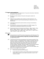
Prepared by: __________________________________
OEWRI Quality Assurance Manager
Date: _____________
Approved by: __________________________________
OEWRI Director
Date: _____________
ID: XRF
Revision: 2
October 2007
Page 2 of 32
Table of Contents
1
Identification of the test method ................................................................................. 3
2
Applicable matrix or matrices...................................................................................... 3
3
Detection Limit ............................................................................................................. 3
4
Scope of the test method ............................................................................................. 3
5
Summary of test method.............................................................................................. 3
6
Definitions ..................................................................................................................... 4
7
Interferences ................................................................................................................. 6
8
Health and safety .......................................................................................................... 7
9
Personnel qualifications .............................................................................................13
10
Equipment and supplies .............................................................................................14
11
Reagents and standards .............................................................................................14
12
Sample collection, preservation, shipment and storage ..........................................14
13
Quality control .............................................................................................................15
14
Calibration and standardization .................................................................................16
15
Procedure ....................................................................................................................16
16
Data acquisition, calculations, and reporting ............................................................24
17
Computer hardware and software ..............................................................................26
18
Method performance ...................................................................................................26
19
Pollution prevention ....................................................................................................26
20
Data assessment and acceptable criteria for quality control measures..................26
21
Corrective actions for out-of-control or unacceptable data .....................................27
22
Waste management .....................................................................................................27
23
References ...................................................................................................................29
24
Tables, diagrams, flowcharts and validation data .....................................................28
ID: XRF
Revision: 2
October 2007
Page 3 of 32
1 Identification of the test method
Operation of the X-MET3000TXS+ handheld elemental analyzer for heavy metal
screening and measurement of contaminated soil. The instrument is classified as a
portable hand-held open-beam X-ray tube based analytical X-ray device.
2 Applicable matrix or matrices
This instrument can be used for natural soil samples.
3 Detection Limit
The detection limits for this instrument are: Antimony = 19ppm, Arsenic = 7ppm,
Barium = 60ppm, Cadmium = 23ppm, Cobalt = 18ppm, Copper = 15ppm, Chromium =
40ppm, Gold = 16ppm, Lead = 15ppm, Mercury = 13ppm, Nickel = 16ppm, Selenium =
4ppm, and Zinc = 8ppm.
4 Scope of the test method
4.1
This procedure will be used as a field and laboratory reference guide for the
collection of heavy metal data from soil samples.
4.2
The instrument measures antimony, arsenic, barium, cadmium, cobalt, copper,
chromium, gold, lead, mercury, nickel, selenium, and zinc concentrations in
natural soil sediments from cutbank profiles, soil cores, or prepared samples in a
laboratory setting.
4.3
The procedures described here present principal components of the instrument,
pre-operating instruction, actual sample analyses, instrument settings, safety
components associated with ionizing radiation, and reporting procedures. The
user should review the instrument manuals for further information about the
instrument.
5 Summary of test method
5.1
The X-MET3000TXS+ handheld elemental analyzer is based on energy
dispersive X-ray fluorescence technology and uses an X-ray tube as the source of
X-rays. The X-ray tube has a Ru target, 40kV HV supply and a high resolution
high count-rate PentaPIN® SiPIN detector system which allows for fast and
accurate soil analyses. The instrument is operated by a HP iPAQ PDA with a
Windows Mobil 5.0 operating system.
5.2
X-rays produced by the instrument, bombard the atoms of the target sample.
Photons collide with electron shells and electrons move. The movement of the
electrons decreases the atom’s energy and an X-ray photon is emitted. The
energy of the photon being emitted is approximately equal to the decrease in the
atom’s energy and the X-rays fluoresce. Each element produces uniquely defined
energy changes and the quantities of electrons in various shells are proportional
to the number of atoms of the element in the sample. The detector system
measures the fluorescent X-rays and the energies that are produced from each Xray. The net intensities of the X-rays are converted into element concentrations
using empirical coefficients and linear and polynomial multi-parameter regressions
derived from calibration standards.
5.3
ID: XRF
Revision: 2
October 2007
Page 4 of 32
The instrument comes pre-calibrated from the manufacturer. The Universal Soils
Fundamental Parameters calibration for assay of 24 common alloying elements
was used. This calibration was based on Certified Reference Materials and
Reference Materials as defined in ISO 30:1981 standard.
5.4
All technicians using the X-MET3000TXS+ must have read this SOP, have been
trained in the appropriate use of the instrument by the responsible party or other
designated authority, have signed an acknowledgement form indicating that they
have read and understand the SOP, and must provide necessary information for
record keeping associated with use of this instrument.
5.5
Charged batteries are inserted into the instrument or the instrument is plugged
into an outlet, the PDA is locked into position, the power key is turned to the “ON”
position to activate the instrument, the yellow indicator light comes on, the peltier
cooler and X-ray tube stabilize, the PDA is turned on, and the software is used to
set up sample data storage information and to operate the instrument.
5.6
Timed Assay’s are used to increase accuracy and precision of soil analyses. The
instrument is activated by a single press of the trigger and measures the sample
for a preprogrammed time which decreases error associated with analysis
duration.
5.7
In the field soil profiles are screened in-situ by creating a divet in the soil that
encompasses the entire analysis window, covering the soil divot with premeasured plastic film, positioning the analysis window into the divot, ensuring a
correct measurement angle of 90°, activating the trigger, and performing a timed
assay. Soil samples screened and collected in the field are dried, ground, and
sieved and placed in plastic freezer bags in the laboratory. The instrument is
positioned in the bench top stand to ensure a correct measurement angel of 90°
and is plugged into an outlet to reduce wear on battery supply. The soil samples
are analyzed in the laboratory by placing the entire bag of sample in the sample
bag holder, closing the door of the holder, activating the trigger, and performing a
timed assay.
5.8
The sample analysis spectra and results are stored on the PDA, the software
program is exited, the PDA is powered off, the power key is turned to the “OFF”
position to deactivate the instrument, and analysis spectra and results are
downloaded to a PC for further processing.
6 Definitions
6.1
Acute Dose: A large amount of radiation received in a short period of time that
results in physical reactions due to massive cell damage.
6.2
Analytical batch: The set of samples processed at the same time.
6.3
Blank: The plastic film used to cover the sample analysis divet during field
determinations or the exact brand of plastic freezer bag containing the samples
during laboratory analysis. Only the plastic film or plastic bag is measured to
ID: XRF
Revision: 2
October 2007
Page 5 of 32
determine additions or interferences present from field procedures, storage
procedures, apparatus, or the laboratory environment.
6.4
Backscattering: Deflection of radiation in a scattering process through an angle
greater than 90°. X-rays that reflect back to the detector and scatter in the
direction of the instrument operator.
6.5
Bremsstrahlung: X-rays or “braking” radiation produced by the deceleration of
electrons. X-ray tubes produce bremsstrahlung as accelerated electrons interact
with the target material.
6.6
Chain of Custody (COC): Used to describe the written record of the collection,
possession and handling of samples. Chain of custody forms should be
completed as described in the Chain of Custody SOP # 1030R01. Chain of
custody (COC) forms are located on a board in Temple Hall 125.
6.7
Characteristic X-rays: A form of electromagnetic radiation with a wavelength in the
range of 10 to 0.01 nanometers, corresponding to frequencies in the range 30
PHz to 30 Ehz. X-rays are a form of ionizing radiation, have no mass or electrical
charge, and are emitted from electrons during electron shell transfers. X-rays can
travel several hundred feet in air, have the highest penetrating power of the types
of ionizing radiation, and are best shielded by using concrete, lead, or steel.
6.8
Check Standard: Standard sediment sample of known concentration and purity
that produce consistent concentrations of analytes. These standards are used to
check instrument performance.
6.9
Chronic Dose: A small amount of radiation received continually over a long period
of time which can be from natural background sources.
6.10
Controlled Area: An area where access, occupancy, and working conditions are
monitored by the responsible person to control radiation exposure to personnel.
6.11
Fundamental Parameters (FP): An Assay & Grade method used for analyses
performed using this SOP that measures the elemental concentrations of
unknown samples. Specifically, “Soil FP” will be used for analyzing heavy
element concentrations in soil.
6.12
Ion: An atom that has lost or gained an electron.
6.13
Ionizing Radiation: Energy in the form of waves or moving subatomic particles that
has enough energy to remove electrons from neutral atoms or molecules.
Ionizing radiation has the potential to alter the chemical structure of living cells.
6.14
Laboratory Duplicate (LD): Two samples taken at the same time and placed under
identical circumstances and that are treated identically throughout field and
laboratory procedures. Analysis of laboratory duplicates indicates the precision
associated with sample collection, preservation, and storage as well as laboratory
procedures.
ID: XRF
Revision: 2
October 2007
Page 6 of 32
6.15
Method detection limit (MDL): The lowest level at which an analyte can be
detected with 99 percent confidence that the analyte concentration is greater than
zero.
a.
To calculate the MDL:
b.
Prepare triplicates of two sediment samples with low organic matter. The
laboratory director or supervisor will choose appropriate samples to use to
determine MDL.
c.
Analyze all samples.
d.
Include all sample processing steps in the determination.
e.
Calculate the standard deviation (s).
f.
From a table of the one-sided t distribution select the value of t for 7 – 1 =
6 degrees of freedom at the 99% level. This value is 3.14
g.
The product 3.14 times s is the desired MDL.
6.16
Minimum Quantification Interval: The lowest level that can be quantitated
accurately and is generally defined as four times the method detection limit =
4(MDL).
6.17
Primary Beam: Ionizing radiation from an X-ray tube that is directed through an
aperture in the radiation source housing for use in conducting X-ray fluorescence
measurements.
6.18
Radiation: Energy in the form of waves or moving subatomic particles that is
classified as non-ionizing and ionizing.
6.19
Relative Percent Difference (RPD): calculated as the difference between a sample
and duplicate results, divided by the average of the sample and duplicate results,
multiplied by 100%.
6.20
Sievert (Sv): Current unit of measure for radiation and the SI unit for dose
equivalence that takes into account the energy absorbed (dose), the quality of
radiation, and the biological effect of different types of radiation in the body. 1Sv =
100rem.
6.21
System Barrier: The portion of an area that clearly defines the transition from a
controlled area to a radiation area an that provides the necessary shielding to limit
the dose rate in the controlled area during normal operation.
7 Interferences
7.1
Window distance from the sample and angle of measurement are important
aspects of these analyses. In field determinations the analysis window will be
placed directly on the plastic film that is placed directly on the soil sample. The
appropriate measurement angle of 90° and timed assays will be used.
7.2
Penetration depth is important for some elemental determinations. Precise
determination of cadmium requires at least 6mm of soil depth.
7.3
ID: XRF
Revision: 2
October 2007
Page 7 of 32
The sample should be as smooth and clean as possible. Rust, oil, and dust
buildup in and around the analysis window will interfere with element analyses.
7.4
The sand fraction of a sample can affect its homogeneity which can alter
elemental determinations. To determine the homogeneity of the sample, it should
be dried and measured at least three times and each element should be
averaged. Particles with diameter >2mm should be removed from the sample and
the samples should be re-analyzed at least three times and each element should
be averaged. If the average of the 2 sets of measurements differ <20% the
sample is considered homogeneous and “semi-quantitative”. If the average of the
2 sets of measurements differ >20% the sample is considered heterogeneous and
particle size is affecting elemental determination. Additional sieving should take
place and will be dictated by the project manager as well as the laboratory
supervisor.
7.5
Soil moisture can interfere with elemental determinations. Sample moisture
should not be higher than 10-20%. Field determinations will produce less
accurate analyses if moist samples are analyzed. All determinations in the
laboratory will be performed using oven-dried sediments.
7.6
X-ray spectra can be very close in energy and can interfere by giving overlapping
peaks. Standards used during manufacturer calibration enhance the isolation of
the specific peak of each element. In addition, Oxford Instruments has a unique
spectrum analysis algorithm that corrects for interfering absorption coefficients
and their effects on calculated concentrations by monitoring the X-ray intensity
from the interfering elements and applying correction factors derived during
calibration.
7.7
Compton or back scattering peaks can interfere with a peak of an element. The
sample bag holder will be used in the laboratory and the background plate should
be used when ever possible in the field to minimize interference.
8 Health and safety
8.1
Researchers, faculty members, staff members, and students will use X-ray
producing equipment in accordance with their departments’ established
procedures and the requirements of this standard practice. Only trained personnel
are allowed to operate this instrument.
8.2
The responsible person for this instrument is the director of the Ozarks
Environmental and Water Resources Institute.
8.3
The manufacturer, Oxford Instruments, designed the X-MET3000TXS+ to conform
to ANSI N43.2-2001 and the 21CFR 1020.40 safety requirements for cabinet Xray systems with the exception of using a totally enclosed beam. Switches,
required keys, indicator lights, and an infrared beam safety sensor were designed
to prevent operators from being exposed to an open X-ray beam. The instrument
was tested by TUV Rheinland against safety requirement of IE 61010-1, “Safety
Requirements for Electrical Equipment for measurement, Control, and Laboratory
ID: XRF
Revision: 2
October 2007
Page 8 of 32
use, Part 1 General Requirements”. The instrument passes the ionizing radiation
leakage requirements in IEC61010-1, section 12.2.1 of <1 µSv/hour at 100mm.
8.4
Ionizing radiation can damage chromosomes of a cell and incomplete repair of
that cell may result in the development of cancerous cells. A red LED indicates
that the instrument is producing X-rays. The instrument’s X-ray beam is
collimated through an aperture that is approximately 0.14 inch in diameter.
8.5
The instrument’s safety system consists of a key lock, three lights, a trigger to
activate X-rays, and an infrared sensor. The key lock controls power to all
components and must be turned on before any actions can take place. The yellow
light indicates that the HV supply is energized when illuminated. The trigger must
be activated for the instrument to produce X-rays. The infrared beam interrupter
sensor must be covered with a sample for the instrument to produce X-rays. The
red light indicates that X-rays are being generated when illuminated.
8.6
The X-ray tube and high voltage power supply are sealed in a fluid filled subassembly. The X-ray tube is shielded by a variety of materials to minimize any
stray X-ray radiation. The X-ray tube and shielding material are mounted in the
instrument housing and the housing is closed using tamper-proof fasteners.
8.7
Radiation dose form an x-ray device must not exceed 20mSv per year averaged
over five years as developed by the International Commission of Radiological
Protection (ICRP-1990), the Biological Effects of Ionizing Radiation (BEIR)
Committee, the US Environmental Protection Agency (EPA), and the National
Council of Radiation Protection (NCRP).
8.8
All technicians will practice As Low As Reasonably Achievable (ALARA) program
guidelines that were designed to prevent unnecessary exposures to humans or
the environment. Technicians will limit the amount of time spent in a radioactive
area because the less time that a person is exposed the smaller dose is received.
Technicians will maintain the maximum possible distance from the radiation
source because as distance increases exposure rate decreases. Technicians will
follow all precautions to shield themselves from exposure. All persons not directly
involved in operating the instrument will remain three feet away from the
instrument during analyses. The sample bag holder attachment shields others in
the laboratory and beyond the walls of the laboratory from exposure which is why
samples will only be analyzed using the sample bag holder while in the
laboratory. Walls and partitions are not safe shields. Radiation does bounce off
surfaces and extends around corners. The beam of radiation, when looking at the
instrument from the top, exits the instrument at approximately 45° to the left.
Never point the instrument at any person when the probe is activated or
otherwise.
ID: XRF
Revision: 2
October 2007
Page 9 of 32
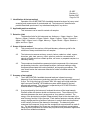
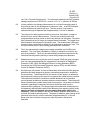
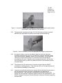
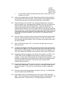
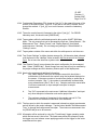
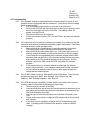
Figure 1. Incorrect Procedure: All persons not directly involved in operating the
instrument will remain three feet away from the instrument during analyses.
8.9
Small sample volume that do not allow the entire measurement window to be
covered present additional risk because part of the primary radiation could go
through the sample un-attenuated. The safety shield for small samples will be
used during analyses of samples that do not cover the entire measurement
window.
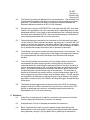
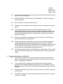
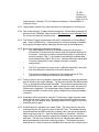
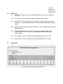
8.10
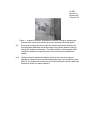
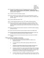
The figure below illustrates the radiation profile of the instrument that was
obtained by measuring doses from backscattering using a low scintillation probe
[NaI(Tl)]. No sample was in place and an artificial instrument condition was used
that did not contain the safety interlocks.
ID: XRF
Revision: 2
October 2007
Page 10 of 32
Figure 2. Background Radiation Measurements: These measurements indicate that the
air kerma rate at 5cm form any accessible surface was lower than 4.38 µGy/hr.
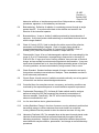
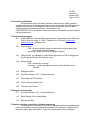
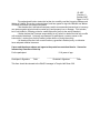
8.11
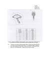
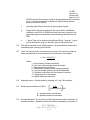
The bone in the finger will absorb radiation about 3-5 times more than soft tissue,
so DO NOT HOLD A SAMPLE IN FRONT OF THE MEASUREMENT WINDOW
WITH THE FINGERS IN THE DIRECT BEAM OR DIRECT THE BEAM AT ANY
PART OF THE HUMAN BODY. Always use the background plate.
ID: XRF
Revision: 2
October 2007
Page 11 of 32
Figure 3. Incorrect Procedure: Do not hold a sample in front of the measurement window
with the fingers in the direct beam or point the beam at any part of the body.
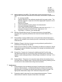
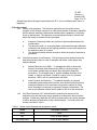
8.12
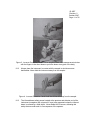
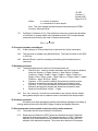
Always place the instrument in contact with the sample to minimize excess
backscatter. Never hold the instrument away from the sample.
Figure 4. Incorrect Procedure: Never hold the instrument away from the sample.
8.13
The infrared beam safety sensor located at the aperture and detector end of the
instrument (nosepiece) will not permit X-rays to be generated unless the infrared
beam is covered by a solid object. Never defeat the IR sensor, defeating this
safety feature could result in over-exposure of the operator.
ID: XRF
Revision: 2
October 2007
Page 12 of 32
Figure 5. Incorrect Procedure: Never defeat the IR sensor, defeating this safety feature
could result in over-exposure of the operator.
8.14
The appropriate measurement angle of 90° will be used at all times to prevent
additional risk associated with primary beam angle and backscattering.
Figure 6. Correct Procedure: Use of the appropriate 90° angle of measurement.
8.15
A beryllium window is used in the radiation detector inside the instrument.
Corrosion of beryllium may occur if it is exposed to moisture, particularly when
ions such as chlorine, sulphates, copper, or iron are present. Do not store the
instrument in high humidity areas or in circumstances where atmospheric
condensation may occur. Beryllium and its compounds are toxic, but the solid
form of beryllium which is used in the detector window of this instrument, poses
no health hazard.
8.16
The instrument will be tested every six months to ensure that the ON/OFF
mechanism is working properly. If the instrument fails, an OIA representative will
be contacted immediately for instructions.
8.17
Instrument use and instrument service records will be maintained for two years or
until the ownership of the instrument is transferred or the instrument is
decommissioned. If the instrument is transferred to non-MSU persons, that
transfer must be reported to regulatory agencies and the OIA representative. The
QA/QC manager will maintain records and report necessary information regarding
the instrument.
ID: XRF
Revision: 2
October 2007
Page 13 of 32
8.18
Any damage to shielding will be immediately recorded and that information will be
given to the QA/QC manager.
8.19
NEVER REMOVE LABELS FROM THE INSTRUMENT. Removal of labels will
void all warranties.
8.20
Never attempt to override any safety feature.
8.21
The battery can be pulled from the instrument during an emergency to terminate
power.
8.22
Timed Assay measurements will be used for all sample analyses. These
measurements allow the user to activate the trigger by pressing the trigger once
verus keeping the trigger pressed during the entire measurement window. The
instrument measures the sample for a specified time each time and increases
precision and safety.
8.23
Dosimetry is available to any student using the instrument or in the laboratory
while the instrument is being operated.
8.24
The primary operator is responsible for the instrument and should always be in
the operators possession either in direct sight or in a secure area. NEVER
LEAVE THE KEY IN AN UNATTENDED ANALYZER. Notify the QA/QC manager
at 417-836-3198 if the instrument is stolen or lost. The QA/QC manager will
contact the police and appropriate regulatory agencies.
8.25
The instrument will be stored in a locked cabinet in the laboratory. The key will be
stored by the QA/QC manager and in a separate location to avoid unauthorized
usage.
9 Emergency Procedures and Call List
9.1
The first action to take in the event of an accident involving the instrument is to
stop all X-ray production by turning the instrument off and removing the battery
pack or unplugging the instrument.
9.2
If any hardware item is damaged, even if the instrument remains operable,
contact the Oxford Radiation Safety Officer (RSO) at 1-847-439-4404. Use of a
damaged instrument may lead to unnecessary radiation exposure and inaccurate
analyses.
9.3
Questions and additional instruction should be directed to the QA/QC manager at
417-836-3198.
9.4
The QA/QC manager will contact university emergency personnel or off-campus
contacts as necessary.
ID: XRF
Revision: 2
October 2007
Page 14 of 32
10 Personnel qualifications
Soil parameters will be collected by Missouri State University (MSU) graduate
assistants who have received appropriate training, prior coursework, and field experience
regarding the collection of soil parameter data, and who are familiar with all of MSU’s
sample handling and labeling procedures. All operators of the
X-MET3000TXS+ will be trained and will know all safety and operation procedures before
using the instrument.
11 Equipment and supplies
10.1
X-MET3000TXS+ Handheld Elemental Analyzer, Oxford Instruments, 945 Busse
Road, Elk Grove Village, IL, 60007, Telephone: 847-439-4404, www.oxfordinstruments.com in shipping case
10.2
Power Supply:
Field - all three batteries charged as indicated by a green status light
while plugged into the charger
Laboratory - power cord, PDA AC adapter and plug
10.3
Charged PDA (as indicated by a solid amber light when the PDA is plugged into
the charger) with Stylus and protection cover
10.4
Sample Holder:
Field – sample film and bags
Laboratory – sample bag holder accessory, safety shield for small
samples
10.5
Background Plate
10.6
Soil Check Sample “2 A1” Oxford Instruments
10.7
Power Key and PDA lock key
10.8
Field or Laboratory Book, Pen
10.9
Instrument Use Record
12 Reagents and standards
11.1
Soil Check Sample “2 A1” Oxford Instruments
11.2
Blank: Sample Film or Sample Bag
11.3
Background Plate
13 Sample collection, preservation, shipment and storage
The analyses are conducted in situ and only samples containing a predetermined
level of contaminants will be collected and transferred to the laboratory. Samples will be
placed into plastic bags and labeled. There are no special provisions for shipment.
ID: XRF
Revision: 2
October 2007
Page 15 of 32
Sample bags should be opened and placed into 60º C oven immediately upon return to
laboratory.
14 Quality control
14.1
Quality control program: The minimum requirements of the quality control
program for this analysis consist of an initial demonstration of laboratory capability
and the periodic analysis of blanks and standard check samples as a continuing
check on performance. The laboratory must maintain performance records that
define the quality of the data that are generated.
a.
b.
c.
14.2
14.3
Analyses of laboratory blanks are required to demonstrate freedom from
contamination.
The laboratory shall, on an ongoing basis, demonstrate through calibration
verification and analysis of the ongoing precision and recovery sample that
the analysis system is in control.
The laboratory should maintain records to define the quality of data that is
generated.
Initial demonstration of performance. The following must be satisfied before the
analytical procedure may be used for samples and before a new analyst may
analyze samples.
a.
Method Detection Limit (MDL) – To establish the ability to detect the
analyte, the analyst shall determine the MDL by carrying through 7 or
more blanks (sample bags and plastic film) through the analytical
procedures. The average value, X, and the standard deviation of the
values, s, shall be calculated. The MDL is equal to 3s (3 x standard
deviation). MDL’s will vary with element and batch.
b.
Initial Precision and Recovery – To establish the ability to generate
acceptably precise and accurate results, the manufacturer performed an
extensive calibration of the instrument using various masses of solids
which illustrate the instrument’s response to analyte concentration. The
instrument calibration should remain stable for the life of the instrument.
Soil Check Standard “2A1” and blank will be measured at the start of the
analytical cycle and after every twenty samples or at least twice during a batch
analysis. A laboratory duplicate (LD) will be analyzed after every twenty samples
or will be analyzed at least twice during a batch analysis. The criteria for these
checks are noted in Table 1.
Table 1. Quality control samples and acceptance criteria.
Check
Acceptance Criteria
Blank
≤ MDL
MD
± 20% of each element
Soil Check Stnd
± 20% of each element
ID: XRF
Revision: 2
October 2007
Page 16 of 32
15 Calibration and standardization
15.1
Errors are inherent in the measurement of X-rays due to the nature of radioactive
disintegration of the ray source.
15.2
Randomness of the emission of X-rays form the sample is random but
predictable.
15.3
Calibration was completed by the manufacturer, Oxford Instruments. The
calibration certificate is kept with original operating and safety manuals in the
OEWRI office.
15.4
The background plate will be used to minimize accuracy errors and reduce
backscattering.
15.5
Any damage to the instrument will be reported to the QA/QC manager. The
instrument will be maintained as defined in the user manual.
15.6
The detection limits for this instrument are: Antimony = 19ppm, Arsenic = 7ppm,
Barium = 60ppm, Cadmium = 23ppm, Cobalt = 18ppm, Copper = 15ppm,
Chromium = 40ppm, Gold = 16ppm, Lead = 15ppm, Mercury = 13ppm, Nickel =
16ppm, Selenium = 4ppm, and Zinc = 8ppm.
16 Procedure
Field
16.1
All three batteries for the XRF should be recharged prior to field deployment. Plug
each battery into the charger located in Temple 125. Each battery could take up
to 2 hours to fully recharge. Each fully charged battery will operate the instrument
for approximately 4 hours.
16.2
The instrument will be reserved and signed out by the primary operator for field
activities for that day. The reservation sheet is located on the cabinet where the
instrument is stored in the OEWRI office. When reserving the instrument, the
primary user will provide their name and the date of use. When the primary
operator actually removes the instrument from the cabinet, they must list a
secondary operator if applicable, field team members, and the date and time that
the instrument was removed from the cabinet. The primary operator is
responsible for the instrument for the entire time that it is out of the cabinet. See
Section 8.23 for additional security information.
16.3
Seat and lock the PDA into the instrument:
a.
Remove the stylus from the PDA computer.
b.
On the right side of the XRF, unlock the PDA computer lock with the key.
Slide the PDA computer into the cradle and take care to seat it on the
connector correctly.
c.
ID: XRF
Revision: 2
October 2007
Page 17 of 32
Lock the PDA computer into place and remove key. Store key in the key
container in the case.
16.4
Insert a fully charged battery into the instrument by pushing it into the handle of
the instrument until it clicks into place. Place the other 2 fully charged batteries
into the performed area in the case that is specifically for the batteries.
16.5
Place the instrument into the XRF case. Arrange all attachments, instrument
safety and power keys, and supplemental materials in the case in a manner that
ensures that they stay in place during transport. Close the case and lock it
making sure that the key for the outside lock is outside of the XRF case. The
instrument will be stored in a cool, dry location within the case during transport to
and from the field. The instrument should never be left unattended and should be
in direct sight of the primary operator for the field activities or in a secure area as
designated by the primary operator. See Section 8.23 for additional security
information.
16.6
Once on location in the field, unlock the case and secure the lock and key within
the case. Insert the instrument power key and turn it to the “ON” position. The
yellow indicator light will illuminate. Wait 1-2 minutes for the peltier cooler and Xray tube to stabilize.
16.7
Push the PDA power switch “ON”. It is located in the upper right corner just
above the screen.
16.8
To adjust the backlight on the PDA use the stylus to tap the on the small circular
slider below the “light bulb” icon located on the right side of the screen and move
it back and forth. When plugged in, the PDA draws power from the battery in the
XRF, so the brighter the backlight, the more power it pulls from the XRF battery.
16.9
Activate the software by tapping on the “Start” menu and then on “X-MET”. The
“X-MET3000” screen will appear and will contain a “Waiting for Connection”
message. A screen with a white background will appear shortly thereafter. If the
software is started before the instrument power is turned on the program cannot
communicate with the instrument. If this occurs, refer to Section 24 for
troubleshooting instructions.
16.10 Fundamental Parameters (FP), shown as “[soil_fp]” in the upper left corner of the
screen, is the method used. This XRF is only set to use the FP method, do not
change the method. If “[soil_fp]” is not on the screen, contact the Laboratory
Director.
16.11 The active results format is illustrated to the right of “[soil_fp]”. For OEWRI field
work, this should read: [OWERI-field].
16.12 Tap anywhere within the white background to bring up the X-MET 3000 Main
Menu. The only menus that can be accessed by users are: “Name Sample”, “Set
Measurement Time”, “Result Format”, and “Display Spectra” (that follows
ID: XRF
Revision: 2
October 2007
Page 18 of 32
measurements, if desired). Do not change any settings in “Select Method” or
“Settings” menus.
16.13 Tap anywhere outside of the menu and within the white space to exit the menu.
16.14 Tap “Output Settings” to define the data storage file. All field data collected must
be saved in the “FieldData” folder located in My Documents on the Storage Card.
Do not save the data files anywhere else.
16.15 The “Results Format” menu chooses the output configuration for the measured
data. Select “[OWERI-field]”. Result formats can vary and will only be modified
by the project manager and the Laboratory Director prior to field deployment.
16.16 Naming the samples and additional information:
a.
Tap “Name Sample” and input the sample name which should be a
combination of location and site number using the keyboard displayed on
the screen. If the name consists of a continuous phrase, a space then a
number (example: “Site 1”), the number is automatically increased after
every measurement (Site 2, Site 3, etc.). Samples cannot be named after
it has been measured, so input sample name prior to sample
measurement.
b.
Tap “OK” to proceed to the next screen “Additional Information” and input
any other descriptive information such as the project title.
c.
The maximum number of characters for the sample name is 20. The
maximum for the additional information is 80 characters.
16.17 The time span in which the sample is measured is based on project requirements
and will be set by the project manager. Tap the button labeled “Set Measurement
Time:” to change the measurement time span. The minimum measurement time
for [OEWRI-field] is set to 5 seconds. When screening in the field, a minimum of
20 seconds is suggested. This measurement time provides relative elemental
concentration peaks, not exact values, which is adequate for screening samples
in the field.
16.18 All samples will be analyzed by using the “Timed Assay” trigger operating mode
which the instrument is set to use. The timed assay allows the operator to push
the trigger once and release versus applying pressure to the trigger for the entire
measurement time span.
16.19 Carefully place the standard in the safety shield. The safety shield is the small
metal box stored in the upper left corner of the XRF case. The standard should
be positioned with the plastic wrap side up taking care to not tear or damage the
plastic wrap on the top of it. Input the sample name as “Standard”. Press the
trigger on the instrument handle to analyze the standard for the set measurement
time span. The red x-ray indicator light will turn on indicating that radiation is
being emitted and the instrument is working properly. The standard has been
analyzed and it is safe to remove the standard when the red x-ray indicator light is
ID: XRF
Revision: 2
October 2007
Page 19 of 32
not illuminated. The results of the measurement will be shown on the white
background in table form. Return the standard to its case and place it back into
the XRF case. The standard will be the first analysis for each field outing.
16.20 Remove the background plate from the XRF case. Place an empty sample bag
on the background plate. Input the sample name as “Bag Blank”. Press the
trigger on the instrument handle to analyze the sample bag for the set
measurement time span. The red x-ray indicator light will turn on indicating that
radiation is being emitted and the instrument is working properly. The analysis is
complete and it is safe to remove the standard when the red x-ray indicator light is
not illuminated. The results of the measurement will be shown on the white
background in table form. The empty sample bag, or “Bag Blank” will be the
second analysis for each field outing.
16.21 Before analyzing samples during screening processes or from the bag, remove
any leaves, grass, or stones from the measurement surface area.
16.22 When screening samples in situ, cover the measurement surface area with a
sample bag to protect the measurement window.
16.23 When screening bagged samples, place the background plate underneath the
sample to prevent interference from materials behind the sample and to reduce xray scattering. The background plate may be used when analyzing soil cores as
dictated by field conditions and project management. Field notes should indicate
whether a background plate was used or not.
16.24 Place the instrument measurement window directly over the sample and hold the
instrument perpendicular to the sample surface during the entire length of the
measurement. Ensure that the thickness of material being sampled is at least 1
cm for best results.
16.25 Press the trigger once to start the analysis and measure elements for the set
measuring time. The red x-ray indicator light will turn on indicating that radiation
is being emitted and the instrument is working properly.
16.26 The results of the measurement will be shown on the white background in table
form.
16.27 Continue analyzing samples either in situ, from cores, or in sample bags, inputting
appropriate sample names. In addition to the PDA, a field notebook should record
sample analyses and their locations. Global positioning points should be
recorded in the field notebook or incorporated into the sample name if various
locations are being analyzed for the project.
16.28 The XRF can be left on between analyses or while moving to different sites. Turn
the PDA off to save battery power. To begin analyzing again, press the power
button in the upper right corner on the PDA.
ID: XRF
Revision: 2
October 2007
Page 20 of 32
16.29 When all analyses are complete, select “Exit” from the Main Menu to exit the
program. The program will prompt for a confirmation in case you mistakenly tap
the “Exit” button.
16.30 Push the PDA power switch “OFF”.
16.31 Turn the instrument power key to the “OFF” position and remove the key.
16.32 Return the XRF back to the case provided for transport. Make sure to verify that
the PDA lock and instrument power keys, standard, and background plate are in
the case. Close the case and lock it making sure that the key for the outside lock
is outside of the XRF case.
16.33 Upon returning to the University, the primary operator will:
a.
Return the batteries to the bench top and plug one in to charge.
b.
Remove the PDA from the instrument and place it in the PDA cradle for
charging and data extraction.
c.
Secure the instrument within the locked cabinet located in the OEWRI
office.
d.
Sign the instrument reservation sheet providing the time and date of return
and verifying that that instrument was returned complete and clean.
16.34 Return the instrument case lock key and the instrument use record to the QA/QC
manager.
Laboratory
16.35 The instrument will be reserved and signed out by the primary operator for
laboratory activities for that day. The reservation sheet is located on the cabinet
where the instrument is stored in the OEWRI office. When reserving the
instrument, the primary user will provide their name and the date of use. When
the primary operator actually removes the instrument from the cabinet, they must
list a secondary operator if applicable, others in the laboratory during analyses,
and the date and time that the instrument was removed from the cabinet. The
primary operator is responsible for the instrument for the entire time that it is out of
the cabinet. See Section 8.23 for additional security information.
16.36 Position the instrument in the bench top stand as shown below. Ensure that the
grooves on the side of the XRF main body and handle are lined up with the stand.
Slip the black rubber band attached to the peg below the handle over the end of
the handle to ensure proper instrument stability.
ID: XRF
Revision: 2
October 2007
Page 21 of 32
Figure 7. Instrument position in bench top stand.
16.37 Attach the auxiliary power cord to the instrument by removing the battery and
plugging the cord into the bottom of the handle. The outlet is located to the right
of the work station and the auxiliary power supply cord should not be removed
from the bench at any time.
16.38 Connect the PDA to the instrument with the remote extension cable using the port
on the front of the instrument. Ensure that the red mark on the round end of the
cable is pointing downward when inserting it into the instrument. The opposite
end of the cord plugs into the bottom of the PDA only one correct way. Do NOT
force the cord into the PDA.
16.39 Place the sample bag holder (large metal box) on the instrument and tighten it to
the instrument. It is a snug fit so be sure that it is fully set on the instrument
before tightening the black knobs. Never analyze any sample in the laboratory
without using the sample bag holder.
16.40 Insert the instrument power key and turn it to the “ON” position. The yellow
indicator will illuminate. Wait 1-2 minutes for the peltier cooler and X-ray tube to
stabilize.
16.41 Push the PDA power switch “ON”. It is located in the upper right corner just
above the screen.
16.42 To adjust the backlight on the PDA use the stylus to tap the on the small circular
slider below the “light bulb” icon located on the right side of the screen and move
it back and forth.
16.43 Activate the software by tapping on the “Start” menu and then on “X-MET”. The
“X-MET3000” screen will appear and will contain a “Waiting for Connection”
message. A screen with a white background will appear shortly thereafter. If the
software is started before the instrument power is turned on the program cannot
communicate with the instrument. If this occurs, refer to Section 24 for
troubleshooting instructions.
ID: XRF
Revision: 2
October 2007
Page 22 of 32
16.44 Fundamental Parameters (FP), shown as “[soil_fp]” in the upper left corner of the
screen, is the method used. This XRF is only set to use the FP method, do not
change the method. If “[soil_fp]” is not on the screen, contact the Laboratory
Director.
16.45 The active results format is illustrated to the right of “[soil_fp]”. For OEWRI
laboratory work, this should read: [OWERI-lab].
16.46 Tap anywhere within the white background to bring up the X-MET 3000 Main
Menu. The only menus that can be accessed by users are: “Name Sample”, “Set
Measurement Time”, “Result Format”, and “Display Spectra” (that follows
measurements, if desired). Do not change any settings in “Select Method” or
“Settings” menus.
16.47 Tap anywhere outside of the menu and within the white space to exit the menu.
16.48 Tap “Output Settings” to define the data storage file. All laboratory data collected
must be saved in the “LabData” folder located in My Documents on the Storage
Card. Do not save the data files anywhere else.
16.49 The “Results Format” menu chooses the output configuration for the measured
data. Select “[OWERI-lab]”. Result formats can vary and will only be modified by
the project manager and the Laboratory Director prior to field deployment.
16.50 Naming the samples and additional information:
a.
Tap “Name Sample” and input the sample name which should be a
combination of location and site number using the keyboard displayed on
the screen. If the name consists of a continuous phrase, a space then a
number (example: “Site 1”), the number is automatically increased after
every measurement (Site 2, Site 3, etc.). Samples cannot be named after
it has been measured, so input sample name prior to sample
measurement.
b.
Tap “OK” to proceed to the next screen “Additional Information” and input
any other descriptive information such as the project title.
c.
The maximum number of characters for the sample name is 20. The
maximum for the additional information is 80 characters.
16.51 The time span in which the sample is measured is based on project requirements
and will be set by the project manager. Tap the button labeled “Set Measurement
Time:” to change the measurement time span. The minimum measurement time
for [OEWRI-lab] is set to 90 seconds.
16.52 All samples will be analyzed by using the “Timed Assay” trigger operating mode
which the instrument is set to use. The timed assay allows the operator to push
the trigger once and release versus applying pressure to the trigger for the entire
measurement time span.
ID: XRF
Revision: 2
October 2007
Page 23 of 32
16.53 Carefully place the standard in the sample bag holder over the sampling window.
Place a small piece of paper over the proximity sensor that is located left of the
measurement window. The standard should be positioned with the plastic wrap
side down taking care to not tear or damage the plastic wrap on the top of it.
Input the sample name as “Standard”. Press the trigger on the instrument handle
to analyze the standard for the set measurement time span. The red x-ray
indicator light will turn on indicating that radiation is being emitted and the
instrument is working properly. The standard has been analyzed and it is safe to
remove the standard when the red x-ray indicator light is not illuminated. The
results of the measurement will be shown on the white background in table form.
Return the standard to its case and place it back into the XRF case. The standard
will be the first analysis for each laboratory batch.
16.54 Place an empty sample bag into the sample bag holder. Input the sample name
as “Bag Blank”. Press the trigger on the instrument handle to analyze the sample
bag for the set measurement time span. The red x-ray indicator light will turn on
indicating that radiation is being emitted and the instrument is working properly.
The analysis is complete and it is safe to remove the standard when the red x-ray
indicator light is not illuminated. The results of the measurement will be shown on
the white background in table form. The empty sample bag, or “Bag Blank”, will be
the second analysis for each laboratory batch.
16.55 Before analyzing samples, remove any leaves, grass, or stones from the
measurement surface area.
16.56 Organize the project sample bags to minimize confusion when preparing samples
and to ensure that sample information is entered into the database correctly.
16.57 Insert each sample bag into the sample bag holder directly over the measurement
window. The thickness of material being sampled should be at least 1 cm, if it is
not, note the approximate thickness in the laboratory notes or incorporate the
information into the sample name.
16.58 Press the trigger on the instrument handle to analyze the sample bag for the set
measurement time span. The red x-ray indicator light will turn on indicating that
radiation is being emitted and the instrument is working properly. The analysis is
complete and it is safe to remove the standard when the red x-ray indicator light is
not illuminated. The results of the measurement will be shown on the white
background in table form.
16.59 Continue analyzing each sample.
16.60 Include a laboratory duplicate for every 20 samples analyzed. Input the sample
name as the original sample name adding “-LD” at the end of the sample name.
Laboratory duplicates for this method are a re-analysis of a sample. Analyze the
sample initially, remove the sample bag, shake it, and reanalyze it. There must
be 2 LD’s for each batch analyzed.
ID: XRF
Revision: 2
October 2007
Page 24 of 32
16.61 Reanalyze the standard after every 20 samples and at the end of the batch
analysis. Input the sample name as “Check Standard”. Reanalyze an empty
sample bag after every 20 samples and at the end of the batch analysis. Input the
sample name as “Bag Blank”.
16.61 The XRF can be left on between analyses.
16.62 When all analyses are complete, select “Exit” from the Main Menu to exit the
program. The program will prompt for a confirmation in case you mistakenly tap
the “Exit” button.
16.63 Push the PDA power switch “OFF”.
16.64 Turn the instrument power key to the “OFF” position and remove the key.
16.65 Return the XRF back to the case. Make sure to verify that the PDA lock and
instrument power keys, standard, and background plate are in the case. Close
the case and lock it making sure that the key for the outside lock is outside of the
XRF case.
16.66 Remove the PDA from the instrument and place it in the PDA cradle for charging
and data extraction.
16.67 Secure the instrument within the locked cabinet located in the OEWRI office.
16.68 Sign the instrument reservation sheet providing the time and date of return and
verifying that that instrument was returned complete and clean.
16.69 Return the instrument case lock key and instrument use record to the QA/QC
manager.
17 Data acquisition, calculations, and reporting
17.1
To down load data from the instrument to a computer:
a.
Ensure that the Microsoft ActiveSync software is installed on the
destination computer.
b.
Insert the PDA into the PDA cradle and plug the USB cord into the
computer.
c.
Navigate to Tools>Explore Pocket PC on the toolbar of the ActiveSync
window that opens. A new Windows Explorer window will open.
d.
Navigate to: Mobile Device> My Windows Mobile-Based Device> Storage
Card> My Documents. If the Storage Card is not visible, turn off the PDA,
gently remove the storage card in the back and reinsert it carefully. Turn
the PDA back on and try to navigate to the destination again.
e.
Choose the data location: FieldData or LabData and then copy and paste
the “*.log.txt” files to any folder on a different drive (local, network, etc.). All
ID: XRF
Revision: 2
October 2007
Page 25 of 32
OEWRI raw data files must be copied to the appropriate project removable
drive. It is recommended that an additional copy the file be saved to
another location for backup.
f.
Open the pasted files to ensure they were properly copied.
g.
Delete all files that were copied from the source folder (FieldData or
LabData) on the PDA. All OEWRI raw data files must be copied to the
appropriate project removable drive before deleting data files from the
PDA.
h.
“*.log.txt” files can be opened using Microsoft Excel. Save the “*.log.txt”
files as Workbooks using the “Save As” option in Microsoft Excel.
17.2
Files will be removed from the PDA regularly. All data should be downloaded
immediately upon returning from the field.
17.3
The X-ray intensity which is measured from the size of the spectrum peaks is
directly proportional to the concentration of the elements in the sample.
I = N/t = (k)(lo)(T)(C)
H
Where:
I = X-ray Intensity (counts per second)
N = Net count (minus background and overlap)
t = Measurement time (seconds)
k = Geometrical constant (sensor-sample geometry)
lo = Source strength (photons per second/steradian)
T = Excitation cross section for the element in question
C = Weight fraction of the element
H = Matrix absorption coefficient.
17.4
Reporting results: Results should be reported to 0.1 mg TN/L precision.
17.5
Relative percent difference (RPD):
(A-B)
AVERAGE(A,B) 100
A = original sample concentration
B = duplicate sample concentration
17.6
Standard Deviation: The evaluation of MDL and precision require calculation of
standard deviation. Standard deviations should be calculated as in equation 2.
∑ x2 – [ (∑ x)2/n)]
s = { --------------------------- } ½
n-1
ID: XRF
Revision: 2
October 2007
Page 26 of 32
Where:
n = number of samples,
x = concentration in each sample.
Note: This is the sample standard deviation calculated by the STDEV
function in Microsoft Excel.
17.7
Coefficient of Variation (Cv%): The evaluation of accuracy require the calculation
of coefficient of variation which is the standard deviation of the multiple sample
measurements divided by the mean of those measurements.
Cv% = (s/ x )100
18 Computer hardware and software
18.1
X-Met software on PDA provided for the instrument by Oxford Instruments.
18.2
This document is created using Microsoft Word. The Word file name for this SOP
is: XRF.doc
18.3
Microsoft Excel is used for recording and reviewing the final data from the
instrument.
19 Method performance
19.1
The desired performance criteria for this measurement are:
a.
Detection limit: varies by element and batch, but the instrument detection
limits are: Antimony = 19ppm, Arsenic = 7ppm, Barium = 60ppm,
Cadmium = 23ppm, Cobalt = 18ppm, Copper = 15ppm, Chromium =
40ppm, Gold = 16ppm, Lead = 15ppm, Mercury = 13ppm, Nickel = 16ppm,
Selenium = 4ppm, and Zinc = 8ppm.
b.
Precision: ± 20%, precision data will be reported as relative percent
difference and project managers will determine what data is used.
c.
Accuracy: ± 20%, accuracy data will be reported as relative percent
difference and project managers will determine what data is used.
d.
Minimum Quantification Interval: 1.0 ppm
19.2
Zinc, iron, chromium, and calcium concentrations are routinely found in blanks
during batch analysis due to materials used to manufacture the sample holder.
20 Pollution prevention
All wastes from these procedures shall be collected and disposed of according to
existing waste policies within the MSU College of Natural and Applied Sciences.
21 Data assessment and acceptable criteria for quality control measures
21.1
The analyst should review all data for correctness.
21.2
Relative percent difference (RPD) should be calculated for pairs of duplicate
analyses to determine precision. The desired precision is ± 20%. Laboratory
duplicate (LD) measurements will be randomly selected from each set of 20
samples in the batch and analyzed. There must be at least two LD analyses
ID: XRF
Revision: 2
October 2007
Page 27 of 32
during each batch analysis. Precision data will be reported as relative percent
difference and project managers will determine what data is used.
21.3
The soil check standard will be used to determine accuracy associated with each
batch. The soil check standard is measured after each set of 20 samples or at
least twice during each batch analysis. The RPD between the average of the
measurements of the check standard for each batch and the initial soil check
standard report will be determined for each element and recorded with each
laboratory report. The soil check standard report is included in Section 26. The
desired accuracy is ± 20%. Accuracy data will be reported as relative percent
difference and project managers will determine what data is used.
21.4
The completed Excel spreadsheet is reviewed by the analyst’s supervisor or the
OEWRI QA officer.
22 Corrective actions for out-of-control or unacceptable data
22.1
The results for precision and accuracy are compared to the acceptable value of ±
20% for this analysis for all analytes. The initial soil check standard (2A1) report
contains the concentrations of each element within the soil check standard and is
included in Section 26.
22.2
Zinc, iron, chromium, and calcium concentrations are routinely found in blanks
during batch analysis due to materials used to manufacture the sample holder.
22.3
If data are unacceptable for any reason, the analyst should review their analytical
technique prior to conducting this analysis again.
22.4
When measurement time is increased the signal, N, increases. The time of
analysis can be increased to increase precision and accuracy. The count rate
should be increased by a factor of four to reduce the standard deviation by onehalf.
22.5
If the sensor is not against the sample at a direct and consistent angle, the
geometrical constant (k) will vary. Maintain direct and consistent angle of
measurement.
22.6
The excitation cross section, T, varies with atomic number of the element and with
source energy. The closer the element’s absorption energy is to the source
energy, the higher the excitation cross section. Certain elemental energies may
further away from the source energy and will result in lower excitation efficiency.
22.7
The instrument may require trouble shooting techniques if the data are
unacceptable. All instrument maintenance will be conducted by the QA/QC
manager or sent to the manufacturer.
23 Waste management
There are no wastes generated using this method. All samples remain is sample
bags and no other consumables are used.
ID: XRF
Revision: 2
October 2007
Page 28 of 32
24 Troubleshooting
24.1
If the software program is started before the instrument power is turned on, the
program cannot communicate with the instrument. If this occurs, follow the steps
below to reset the PDA.
a.
Exit the software program and turn off power to the instrument.
b.
Remove the PDA from the instrument and use the stylus to press the reset
button on the bottom left corner of the PDA. The loading screen will
appear, turn the PDA off.
c.
Remount the PDA onto the instrument.
d.
Switch the instrument power “ON”, turn the PDA on, and start the software
program.
24.2
If the instrument will not perform an analysis of a sample, first, make sure that the
instrument was powered on before the software program was started. If that does
not initiate analyses, follow the steps below.
a.
Make sure that the infrared sensor is covered completely with sample.
The safety sensor must be activated before analyses can begin.
b.
Make sure that the yellow power light is on. If the yellow light is dim or is
blinking, change the battery or connect the instrument to the AC adaptor.
c.
If the instrument was powered before the software program and the PDA
has been reset and the PDA is still not communicating with the instrument,
make sure that the PDA is seated properly on the instrument. Exit the
software, remove the PDA, reseat the PDA, and restart the software
program.
d.
If the sample surface is too darkly colored to reflect light, the infrared
sensor may not activate. If the sample is clearly dark and the instrument
will not perform an analysis, insert a piece of white paper between the
sample and the infrared sensor.
24.3
If the X-MET software locks up, PDA memory may be the cause. Close all other
programs by tapping on “Start”, then “Settings”, then “System” tab, then
“Memory”, then “Running Programs”, then “Stop All”.
24.4
If the PDA touchscreen completely “freezes” and the reset button did not fix the
problem, perform a hard reset by following the steps below.
a.
Take the memory card out of the PDA.
b.
Press and hold down the left and right function buttons at the bottom of the
front panel and simultaneously press the reset button at the bottom of the
PDA until the display turns dark.
c.
Use the stylus to press the reset button on the bottom left corner of the
PDA.
d.
Follow screen instructions to realign the PDA screen and set the time and
date settings.
e.
If this does not fix the problem, recharge the PDA and perform a hard
reset. If recharging the PDA does fix the problem, contact the QA/QC
manager.
ID: XRF
Revision: 2
October 2007
Page 29 of 32
25
26
References
25.1 19 CSR 20, “Radiation Protection”, Missouri Department of Health and Senior
Services.
25.2
29 CFR Part 1910, Occupational Safety and Health Administration.
25.3
N 43.2-2001, “Radiation Safety for X-ray Diffraction and Fluorescence Analysis
Equipment”, American National Standard Institute (ANSI)/Health Physics Society
(HPS).
25.4
Missouri Statutes Section 192.400, “Radiation Control”, Department of Health and
Senior Services.
25.5
US EPA Method 6200, “ITRV: XRF Technologies for Measuring Soil and
Sediment (Niton XLt 700 Series XRF)”, EPA publication EPA/540/R-06/004,
February 2006.
25.6
User’s Manual. 2006. Eureka Environmental Engineering, Austin Texas.
25.7
Safety Manual. 2004. Eureka Environmental Engineering, Austin Texas.
Appendices
Figure 8. Soil Check Standard (2A1) Report.
ID: XRF
Revision: 2
October 2007
Page 30 of 32
XRF SOP ACKNOWLEDMENT FORM
Name ________________________________________ SS # ___________________
Address ______________________________________________________________________
Street/Box
City
State
Zip
Phone (local): ___________________________(permanent) _____________________
Name of Guardian:
______________________________________________________________
Guardian’s Address ______________________ Phone: _________________________
ACTIVITY INFORMATION
Type of Activity: Operation of the X-MET3000TXS+ handheld elemental analyzer for heavy metal
screening and measurement of contaminated soil.
ACKNOWLEDMENT
“I, the undersigned participant, being the age of 18 or above, desire to participate in the
Activity described above, which includes transportation to and from Springfield. The Activity is
potentially hazardous and I have read and understand the standard operating procedures (SOP)
associated with this instrument. I should not engage in the Activity unless I am alert and
observant, which I represent myself to be. I assume any and all risks associated with the Activity
including but not limited to, fall, personal injury, collision with other persons, the effects of
weather, including high heat and humidity and motor vehicle transportation, all such risks being
known and appreciated by me. I attest that I am sufficiently physically fit to participate in this
Activity.
Knowing the risks, and in consideration of being permitted to participate in the Activity
described above, I for myself and my personal representatives, heirs, and assigns, do hereby
hold harmless and release, waive discharge and covenant not to sue the board of Governors of
Missouri State University from any and all claims or liability on account of death or injury to
person or property of the undersigned of any kind of nature whatsoever arising out of or in any
way connected with, the undersigned’s participation in the Activity and transportation activities,
even though the claim or liability may arise out of the negligence or carelessness on the part of
Missouri State University, or any third person, whether foreseen or unforeseen, known or
unknown.
The undersigned hereby expressly agrees that this release and waiver is intended to be as broad
and inclusive as permitted by the laws of the State of Missouri and that if any portion hereof is
held invalid, it is agreed that the balance, notwithstanding, continues in full legal force and effect.
ID: XRF
Revision: 2
October 2007
Page 31 of 32
The undersigned further states that he/she has carefully read the foregoing Release and
Waiver of Liability, knows the contents thereof, and has agreed to sign this Release and Waiver
of Liability as his/her own free act and deed.
I also declare that I will take all necessary and/or recommended precautions to insure my
own person against physical and/or mental injury and property loss or damage. This includes,
but is not limited to, following printed or verbal instruction given by the activity leader(s).
I further declare that I assume responsibility for my actions or behaviors that may conflict
with accepted standards. University requirements for participants, common sense or the
instructions, I receive from Activity leader(s) either before or during the activity.
I do hereby affirm that I am covered under my guardian’s medical policy or otherwise
have adequate medical insurance.
I have read the above release and agree to the provisions contained herein. I have also
informed my Guardian of this trip.
For the participant:
____________________________
Participant’s Signature
Date
If 18 years of age:
_________________________________
Guardian’s Signature
Date
This form should be returned to the QA/QC manager in Temple Hall Room 326.
ID: XRF
Revision: 2
October 2007
Page 32 of 32


![2013 Gun List internet copy[2]](http://vs1.manualzilla.com/store/data/005851443_1-16b4e1bd3fc391c408d2005c48a2e336-150x150.png)