1
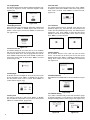
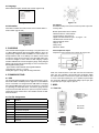
FG-7000T Digital Torque Gauge
Operation Manual
SHIMPO INSTRUMENTS
Operators should wear protection such as a mask and gloves in case
pieces or components break away from the unit under test.
Whether the unit is ON or OFF, DO NOT exceed the capacity of the
sensor. NEVER exceed 120% of the rated capacity, or the torque sensor
will be damaged. At 110% of the rated capacity the display will flash
a warning.
If mounting FG-7000T Series Digital Torque Gauges, use M6 mounting
screws with a maximum insertion depth of 7 mm into the gauge. Hand
tightens mounting screws, DO NOT use tools. Do not use damaged
clamp.
Measure in line torque only. DO NOT attempt to measure forces at an
angle to the sensor – damage to sensor may result.
Do not attempt to repair or alter this instrument. Warranty will be voided
and damage to the unit may result.
Use and store within the stated temperature and humidity ranges, or
damage and failure may result.
If not using this instrument for extended periods of time, remove the
batteries to prevent potential battery leakage from causing product
damage.
DO NOT use tools to over torque the connection adapter. Hand-tighten
only so damage does not occur.
The FG-7000T Series digital torque gauges provide testing flexibility with their external torque sensor input. Torque sensors
with standard chuck adapter are immediately recognized when
connected to the display base and are available for your specific
testing needs in 1 N-m (9 in-lb) 5 N-m (44 in-lb), 10 N-m (88 inlb) capacities. The multiple-language FG-7000T’s provide menu
programming for easy selection and set-up of the instrument to
your desired requirements. Four selectable modes of operation
include: Track mode for live readings, Peak mode for displaying
the maximum reading, First Peak where only the initial peak is
recorded once a decrease is sensed and Preset which initiates
user-programmed tolerance alarms for go/no go testing. The
display has two selectable operations, numerical view with directional bar graph or graphical view with directional bar graph.
In graphical view when alarm tolerances are set, the process is
plotted in relation to the upper and lower limit graph lines. Combined with the go/no go icons, a simple pass/fail determination is
recognized. These high-tech instruments can data log a reading
at the push of a button for simple data acquisition or be set to
continuous data storage. Data can be viewed on the screen, sent
to the optional printer, or loaded to be analyzed and graphed on
the free software program. The 1,000 point memory with definable
groups allows for multiple tests to be recorded and easily separated upon loading. In addition, the comparator output can be set
up for integration of the instrument into a quality system for repetitive testing such as on a production line. The FG-7000T’s robust
housings are designed to fit perfectly in the operator’s hand for
portable testing. The large back-lit, 180° auto-reversible display,
CW/CCW directional bar graph, combined with the dual labeled
key pad allows for usage of the gauge in various positions while
still being able to easily view and operate. These various features
make the FG-7000T the ideal torque instrument for various applications such as closing or opening analysis of containers, valves
and door hardware, failure or destructive torque testing, or almost
any torque testing requirement involving incoming quality inspection, finished goods testing to R&D.
SPECIFICATIONS
Accuracy: ± 0.3% F.S.
Selectable Units: N-m, N-cm, kgf-cm, lbf-in (Depending on
Range)
Overload Capacity: 120% of F.S. (LCD flashes beyond 110% of
F.S.)
Measurement method: Peak, First Peak Preset or Track Mode
Data Sampling Rate: 1000 Hz
Display: 160*128 dot matrix LCD with LED Backlight
Display Update Rate: 10 times/second
Resolution: (See page 2 Resolution Table)
Memory: 1000 data
Set Point: Programmable high and low limits
Battery Indicator: Display flashes battery icon when battery is
low
Power: 3.6VDC 800mAH Ni-MH rechargeable batteries
Battery Life: Approximately 16 hours continuous use per full
charge
Charger / Adapter: Universal USB/BM charger, Input: 110 ~
240VAC
Temperature Effects: <0.054% per °F (0.03% FS per °C)
Outputs: USB, Serial Port RS-232, High & Low Limit NPN
Operating Temperature: 14 to 104°F (-10 to 40°C)
Storage Relative Humidity: 20 to 80%
Housing: Aluminum
Storage Temperature: -4 to 122°F (-20 to 50°C)
Oper. Relative Humidity: 5 to 95%
Dimensions: 5.7 x 2.9 x 1.4” (145 x 73 x 35.5 mm)
Product Weight: 3.7 (1.7 kg)
Package Weight: 5.5 (2.5 kg)
Warranty: 1 year
Included Accessories: Key Chuck, AC Adapter/Charger, USB
cable, calibration cert.
1. LCD SCREEN STANDARD VIEW
Test Mode Icons:
Track: Real Time, live measuring mode
Peak: Reading will not change until a higher value is measured
Preset: Set the upper & lower limit for GO/NG testing
First Peak: Captures First Peak after a decrease has been
detected. Drop Ratio set in menus.
4
9
2. Battery Icon: Battery level or charging status. Flashes when gauge needs to be recharged.
3. OK/OV Indicator:
2
Under Lower Limit
Between Low Limit & Upper Limit
7
Over Upper Limit
Digital View
4. Torque Icons: Indicates force direction.
Clockwise (CW)
Counterclockwise (CCW)
1
5. Current measured value
6. Analog Bar: Indicates current position within full scale. When
the bar enters the area enclosed by the dotted line, this
signifies the full scale capacity is exceeded by an overload
condition.
7. Storage Icon: Indicates data is being saved.
8. System time
9. Units Indicator: Selected engineering unit.
10. Load Cell Capacity Icon:
3
5
6
If no load cell is connected, this symbol appears & blinks
8
10
Graphic View
2. RESOLUTION TABLE
Model
1 N-m
5 N-m
10 N-m
2
N-m
N-cm
kgf-cm
lbf-ft
lbf-in
Interface Type
Capacity
1
100
10
-
8.9
Resolution
0.001
0.1
0.01
-
0.005
Capacity
5
500
50
3.68
44.3
Drill
Chuck
1-10 mm
(0.034 to 0.39 in)
Resolution
0.001
0.1
0.01
0.001
0.01
Capacity
10
1000
100
7.38
88.5
Resolution
0.01
1
0.1
0.001
0.01
Drill Chuck
2-13 mm
(0.079 to 0.512 in)
3. KEY FUNCTIONS
From the home screen, touch “MENU” to enter the main menu.
(Figure 4-1)
All keys are capacitive touch.
ON/OFF: Push for 2 seconds to power On or Off
During Measurement: Print the current force value or store data, depending on the key setting. (See 4.5.8 for key setting)
In Menus: Back or quit.
During Measurement: Enter the menus.
In Menus: Select or Enter
During Measurement: Track mode, tares weight of
attachment. In Peak & Auto Peak modes, resets the
peak value.
In Menus: Moves selection up or increases the value.
Figure 4-1a
Figure 4-1b
4.2 Measurement
The Measurement menu contains six selectable items: Unit,
Group, Test Mode, Alarm and Calibration. (Figure 4-2a)
During Measurement: Changes the measure mode from Track, Peak, Auto Peak, First Peak
In Menus: Moves selection down or decreases the
value.
Figure 4-2a
4.2.1 Unit
The measuring unit can be selected under this menu. Different range models may have different unit selection capabilities. Touch “ZERO” or “MENU” keys to shift to the next selection. Press “LOG” to cancel or touch “MENU” to confirm and
exit. (Figure 4-2c)
4. ADVANCED MENU OPTIONS
4.1 Menu Structure
Unit
Group
Measurement
Test Mode
Alarm
Figure 4-2c
Calibration
Storage Mode
Browse All
Memory
Browse Selected
Delete Selected
Delete All
Print Recent
Printing
Print Selected
4.2.2 Group
When several test samples need to be measured, the samples can be coded into groups. The range is 01-99. When set
to “00”, become, “01” automatically. Press “ZERO” to adjust
the value, touch “MODE” to shift to the next position. Touch
“LOG” to cancel; press “MENU” to confirm and exit. (Figure
4-2d)
Print All
Menu
Display Mode
Display Direction
Auto Power Off
Backlight
System
Key Tone
Figure 4-2d
Date/Time
Password
Key Setting
RS-232 Baud Rate
Default Setting
Language
Information
3
4.2.4 Test Mode
Change the mode of operation between the four modes.
Press “ZERO” or “MODE” keys to select. Press “LOG” to cancel or “MENU” to confirm and exit. This adjustment can also
be changed at the home screen display by simply pressing
“MODE” (Figure 4-2f). First Peak Mode will display a drop ratio menu (Figure 4-2g). This drop ratio actives the first peak
recording.
Load a standard force on the gauge. Wait a moment for the
force to stabilize. The current value (2) should equal the standard force applied.
If the values do not match, press “ZERO” and “MODE” keys to
correct the standard input value (3).
Press “MENU” to enter the next calibration point. After any of
the calibration points have been completed, touch “LOG” to
exit the calibration mode. Then save the calibration or discard
by pressing “Yes” or “No”.
After completing the calibration of the 5th point, the confirmation window will automatically ask to “Save and Exit” by selecting “Yes” or “No”. (Figure 4-7c)
Figure 4-2f
Figure 4-2g
4.2.5 Tolerance
In the Preset menu, program high and low limit values to enable ok/ov testing. The lower limit value cannot be greater than
the upper limit value, and neither limit value can be greater
than 110% of the rated capacity. Press “ZERO” to adjust the
value, touch “MODE” to shift to the next position. Press “LOG”
to cancel; touch “MENU” to confirm and exit.
(Figure 4-2h)
Figure 4-7c
Press “ZERO” or “MODE” to select, then press “MENU”. If
“Yes” is selected, “Calibration Complete!” is displayed.
NOTE:
1. Ensure that the tare of attachment has been cleared before
calibration.
Figure 4-2h
4.2.6 Alarm
The alarm function can be turned on or off to activate or deactivate the user programmed tolerances set in the Tolerance
Menu. Touch “ZERO” or “MODE” keys to shift to the next position. Press “LOG” to cancel, touch “MENU” to confirm and
exit. (Figure 4-2i)
2. For higher measuring precision throughout the test range,
calibrating a point with a force at full scale is recommended.
3. Compression and tension calibrations are saved separately.
The force gauge can identify the direction of the force, but each
must be completed in a separate procedure.
4.3 Memory
In the Memory menu, the user can browse, delete, or print the
data. (Figure 4-3a)
Figure 4-2i
4.2.7 Calibration
Users can field-calibrate the gauge. First, enter the system password (Default is 123) by pressing the “ZERO” and
“MODE” keys. Then press “MENU” to confirm. (Figure 4-7a)
1
2
3
Figure 4-7a
jCalibration Point
kCurrent Value
lStandard Input Value
4
Figure 4-7b
Figure 4-3a
4.3.2 Browse All
The data will be displayed. Touch “ZERO” or “MODE” keys to
shift to the next position. Touch “MENU” to see Delete or Print
options. Touch “LOG” to go back. (Fig. 4-3c)
Figure 4-3c
4.3.4 Browse Selected
User can choose the data to browse. The available range of
data stored is shown. Touch “ZERO” to adjust the value. Press
“MODE” to shift to the next position. Press “LOG” to cancel;
touch “MENU” to confirm. (Figure 4-3d)
Figure 4-3d
4.3.5 Delete Selected
Select the range of data to be deleted. Touch “ZERO” to adjust
the value. Press “MODE” to shift to the next position. Touch
“LOG” to cancel; touch “MENU” to confirm. (Figure 4-3e)
Figure 4-3e
4.3.6 Delete All
In this menu, a prompt will appear. All data will be deleted by
selecting “YES” and canceled by selecting “NO” or pressing
“LOG”. (Figure 4-3f)
Figure 4-4b
4.4.1 Print Recent
Print recently stored data in this menu. The range is 0~19. (Figure 4-4c) Touch “ZERO” to adjust the value. Touch “MODE”
to shift to the next position. Press “LOG” to cancel. Press
“MENU” to confirm.
Figure 4-4c
4.4.2 Print Selected
In this menu, select the data range to print. Touch “ZERO” to
adjust the value, touch “MODE” to shift to the next position.
Press “LOG” to cancel; touch “MENU” to confirm. (Figure 4-4d)
Figure 4-4d
4.4.3 Print All
To print all data saved in memory, a prompt window will display. All data will be printed by selecting “YES”. This operation
will be canceled by selecting “NO” or touching “LOG”. (Figure
4-4e)
4.5 System
Figure 4-3f
Figure 4-4c
Figure 4-4e
Under the System menu, several parameters may be set per Figure 4-5a, 4-5b.
4.4 Printing
The Printing menu contains three selectable items: Print Recent,
Print Selected Print All and Print Diagram. (Figure 4-4a) The data
saved in memory can be output to a printer through the serial port
RS232 connection. (See 6.2.1 RS232 for more information) An example test report is shown in Figure 4-4b, 4-4c.
Figure 4-5a
Figure 4-5b
Figure 4-4a
5
4.5.1 Display Mode
Two display modes may be selected: Digital and Graphic (Figure 4-5c). If diagram is chosen, select the diagram’s scale.
(Figure 4-5d)
Figure 4-5c
Figure 4-5d
4.5.2 Display Direction
Select the mode of the LCD display: Automatic, Obverse and
Reverse. Touch “ZERO” or “MODE” keys to shift to the next
position. Press “LOG” to cancel; Push “MENU” to confirm and
exit. (Figure 4-5d)
Figure 4-5e
4.5.3 Auto Power Off
To maximize battery life, the power can be set to shutdown
after non-use. The time can be set in this menu. The range is
01-99 minutes. When set to “99” the gauge will never turn off.
Touch “ZERO” to adjust the value, touch “MODE” to shift to the
next position. Press “LOG” to cancel; Push “MENU” to confirm
and exit. (Figure 4-5f)
Figure 4-5f
4.5.4 Backlight
Under this menu, the backlight can be set to ON, OFF or have
an auto shutdown. Touch “ZERO” or “MODE” keys to shift to
the next position. Press “LOG” to cancel. Press “MENU” to
confirm and exit. (Figure 4-5g)
Figure 4-5g
4.5.5 Key Tone
Turn the key sound ON or OFF. Touch “ZERO” or “MODE”
keys to shift to the next position. Touch “LOG” to cancel; Press
“MENU” to confirm and exit. (Figure 4-5h)
4.5.6 Date/Time
The system time may be set under this menu. Touch “ZERO”
to adjust the value. Press “MODE” to shift to the next position.
Touch “LOG” to cancel. Press “MENU” to confirm and exit.
(Figure 4-5i)
Figure 4-5i
4.5.7 Password
The system password can be changed. First, enter the old
password (Figure 4-5j), then enter the new password and
confirm the new password (Figure 4-5k). The default System
password is “123”. Touch “ZERO” to adjust the value. Press
“MODE” to shift to the next position. Touch “LOG” to cancel;
Push “MENU” to confirm and exit.
Figure 4-5j
4.5.8 Key Setting
Set the default function of the “LOG” key from the home
screen. The function can be set to print or store the current
displayed value. Press “ZERO” or “MODE” to select the proper
setting. Press “LOG” to cancel; touch “MENU” to confirm and
exit. (Figure 4-5l)
Figure 4-5l
4.5.9 RS232 Baurate
Adjust Baurate to available bits per second selection in Figure
4-5m.
Figure 4-5m
4.5.10 Default Setting
If you make a selection that you feel has caused the gauge
to operate improperly, you can restore it to the factory default
settings. Carefully use this function! (Figure 4-5n, Figure 4-5o)
Figure 4-5l
6
Figure 4-5h
Figure 4-5k
Figure 4-5o
4.6 Language
Select between English, German and Chinese (Figure 4-6a)
Figure 4-6a
4.8 Information
Information includes the model, version of the software and the
serial number. (Figure 4-8a)
1N-m
SN
Figure 4-8a
5. CHARGING
The FG-7000L Series Digital Force Gauge is supplied with a set
of 3 Nickel Metal Hydride AAA rechargeable batteries, which are
supplied fully charged to allow immediate use. Users need to recharge batteries when a low battery icon flashes. Users should
connect the gauge and the charger using the USB cable. Then
connect the charger to an AC socket to start charging. Laptops
and other USB devices can also charge the gauge. A fully charged
battery pack will provide approximately 16 hours of constant use.
Rechargeable battery pack:
- Type: Ni-MH 3.6VDC 800mAH rechargeable batteries
-Charging time: approx. 3~4 hours
-Battery life: approx. charge and discharge 500 times
6. COMMUNICATIONS
6.1 USB
The FG-7000L Series Digital Force Gauge is designed in accordance with USB2.0 standard protocol. (Figure 6-1a) The USB Port
can be connected to a charger with the USB cable for charging
the internal Ni-MH battery and can be connected to a computer
for uploading the measured values. Connect the gauge and the
computer with the USB cable, then open the computer software.
Upload the values. Please refer to the software manual for additional information.
Figure 6-1a
6.2.1 RS232
The RS232 serial port is used to connect a printer to print the
memory data.
RS-232 specifications are as follows:
-Data transmission: serial interface
-Synchronization: asynchronous
-Signal Level: RS-232 level, logic 1:-5v, logic 0: +5v
-Hardware Flow Control: None
-Data word length: 8 bits
-Stop bit: 1bit
-Parity: None
-Baud rate: 38400
6.2.2 Comparison Output
Comparison Output internal circuit shown as Figure 6-2a.
When the measured value is less than the lower limit tolerance
value, the “pc2” operates, 7pin and 6pin line conduction. When
the measured value is more than the upper limit tolerance value
or 110% of the rated capacity, the “pc1” operates, 4pin and 6pin
line conduction. Maximum permissible voltage: 7pin to 6pin, 4pin
to 6pin 35V; 6pin to 7pin, 6pin to 4pin 6V.
7. MISC.
7.1 Parts List
6.2 Port Pin Assignments
Sensor
PIN#
Definition
1
RS232-Transmit
2
RS232-Receive
3
RS232-Ground
4
Comparison Output B
5
Reserved
6
Comparison Output C
7
Comparison Output A
8
Reserved
Figure 6-2a
Key Chuck
Not Shown
Indicator
Charger
Manual
USB Cable
7
7.2 Diagram
Sensor
Adapter
Connection
160*128 Dots LCD
(See LCD Screen)
Robust Metal Housing
Capacitive
Touch Keys
USB Port:
Recharge the internal
Ni-MH battery or
connect to PC
Communications Port
(See Figure 6-1a)
7.3 Dimensions
Torque Sensor Dimensions
Capacity
D0
L0
L
L1
D1
L2
1 N-m
Ø 40
48
156
88
Ø 42.8
216
5 N-m
Ø 46
48
156
88
Ø 42.8
216
10 N-m
Ø 46
48
178
88
Ø 52.8
240
ELECTROMATIC Equip’t Co., Inc., 600 Oakland Ave, Cedarhurst, New York 11516 - USA
Tel: 800-645-4330 / 516-295-4300 Fax: 516-295-4399 Web: CheckLine.com Email: [email protected]


![j:j_"Xt$l"j:]:":,lg]:"r/Human Resources have been duty - e](http://vs1.manualzilla.com/store/data/005657435_1-26d97049bf04f0fd92265d73e45a9ab3-150x150.png)