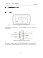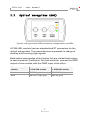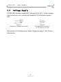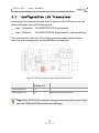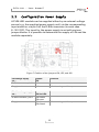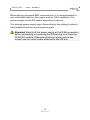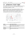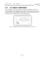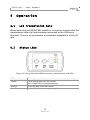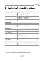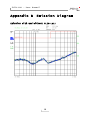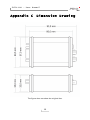
1
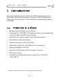
PLIN-LWL
Optical Coupler for
LIN Data Transmission
User Manual
Document version 1.1.0 (2015-11-16)
PLIN-LWL – User Manual
Relevant products
Product Name
Model
Part number
PLIN-LWL
IPEH-004049
All product names mentioned in this document may be the trade marks or registered
trademarks of their respective companies. They are not explicitly marked by „™“and
„®“.
Copyright © 2015 PEAK-System Technik GmbH
Duplication (copying, printing, or other forms) and the electronic distribution of this
document is only allowed with explicit permission of PEAK-System Technik GmbH.
PEAK-System Technik GmbH reserves the right to change technical data without
prior announcement. The general business conditions and the regulations of the
license agreement apply. All rights are reserved.
PEAK-System Technik GmbH
Otto-Roehm-Straße 69
64293 Darmstadt
Germany
Phone:
Fax:
+49 (0)6151 8173-20
+49 (0)6151 8173-29
www.peak-system.com
[email protected]
Document version 1.1.0 (2015-11-16)
2
PLIN-LWL – User Manual
Contents
1
1.1
1.2
1.3
2
2.1
2.2
2.3
3
3.1
3.2
3.3
3.4
4
4.1
4.2
5
Introduction
4
Properties at a Glance
Operation Requirements
Scope of Supply
Connectors
4
5
5
6
LIN
Optical Waveguides (OWG)
Voltage Supply
Configuration
6
7
8
9
Configuration LIN Transceiver
Configuration Power Supply
Configuration Internal Supply
LIN Master Termination
Operation
10
11
13
14
15
LIN Transmission Rate
Status LEDs
15
15
Technical Specifications
16
Appendix A
CE Certificate
17
Appendix B
Emission Diagram
18
Appendix C
Dimension Drawing
19
3
PLIN-LWL – User Manual
1
Introduction
For use in explosion-proof areas or for EMC measurements, the
PLIN-LWL can be used to replace a stretch of LIN network with a
fiber-optic line at any point. The modules are supplied with power
externally.
1.1
Properties at a Glance
Bit rates from 2.4 kbit/s 1 up to 20 kbit/s
2 types of the TJA1028T LIN transceiver built in, use depending
on the bit rates and EMC requirements
LED display for power supply and transceiver status
Switchable master termination
LIN bus connection via D-Sub, 9-pin
Fiber-optic duplex line, 62.5/125 μm, ST connectors
Supply voltage 8 to 30 V DC
Supply via D-Sub 9-pin or DC connector (jumper)
Aluminum casing
Extended operating temperature range from -40 to 85 °C
(-40 to 185 °F)
1
2.7 kbit/s if 16 (instead of 13) bits are used for the break pulse
4
PLIN-LWL – User Manual
1.2
Operation Requirements
LIN network (Master or Slave termination can be selected per
module)
D-Sub sockets for connection to the PLIN-LWL modules
Power supply with power supply unit or via the D-Sub connector
1.3
Scope of Supply
2 PLIN-LWL modules including power supply units
A choice of 5 or 10 m FO cable, 62.5/125 μm duplex line ST
connector, other lengths available on request
Manual in PDF format
5
PLIN-LWL – User Manual
2
2.1
Connectors
LIN
Figure 1: Casing side with toggle switch and D-Sub connector for LIN
The LIN bus is connected to the 9-pin D-Sub connector on the left
casing side.
Figure 2: Pin assignment D-Sub connector
Pin 9 can be used to supply a PLIN-LWL module. See section 3.2
Configuration Power Supply on page 11 for further information.
6
PLIN-LWL – User Manual
2.2
Optical Waveguides (OWG)
Figure 3: Casing side with OWG connectors, voltage socket, and LEDs
A PLIN-LWL module has two standardized ST connectors for the
optical waveguides. The connections are separately in charge of
sending and receiving light signals.
Both optical waveguides of the duplex line are marked with colors
at each connector (red/black). For both modules, connect the OWG
output of one module with the OWG input of the other.
Optical wave guide
(marker)
Connector at
1st PLIN-LWL module
Connector at
2nd PLIN-LWL module
Red
OWG IN (gray)
OWG OUT (light gray)
Black
OWG OUT (light gray)
OWG IN (gray)
7
PLIN-LWL – User Manual
2.3
Voltage Supply
A PLIN-LWL module needs a DC voltage of 8 to 30 V. At the voltage
input socket you can connect the supplied 12-Volt power supply
unit.
Figure 4:
Assignment voltage input socket
Figure 5:
Diameter barrel connector:
a = 5.5 mm, b = 2.1 mm
See section 3.2 Configuration Power Supply on page 11 for further
information.
8
PLIN-LWL – User Manual
3
Configuration
At the PLIN-LWL housing, a termination for the Master operation
mode can be switched on with a toggle switch. On the circuit board
of the module, you can do the following jumper settings affecting
the basic operation:
Choice between High-speed and Low-speed LIN transceiver
Configuration of the power supply
Configuration of the internal supply
Tip: At delivery, the PLIN-LWL modules use the High-speed
transceiver for the data transmission. The power supply for the
module and the LIN bus is configured to be done with the
power supply units via the DC socket. If you use this common
configuration, a change of the settings as described in this
chapter is not needed.
For doing jumper settings, the circuit board must be taken out of the
casing.
To do so, do the following:
1.
If extant, remove the protecting caps from the OWG connectors (right housing side).
2.
Remove the two screws on the left housing side (the one
with the D-Sub connector).
3.
Pull the circuit board with the lid out of the case.
After changing the settings (see the following subsections), the
assembly is done in the reversed order.
9
PLIN-LWL – User Manual
3.1
Configuration LIN Transceiver
According the highest bit rate that is used on the LIN bus, you can
select between two LIN transceivers:
max. 10,4 kbit/s: TJA1028T/5V0/10 (Low-speed)
max. 20 kbit/s:
TJA1028T/5V0/20 (High-speed, default setting)
The transceiver with the /10 ending generates less steep slopes,
thus the electromagnetic compatibility is enhanced.
Figure 6: Position of the jumper blocks JP3 and JP7
Transceiver
Jumper setting
JP3 and JP7
Low-speed (/10)
1-2
High-speed (/20)
2-3
Comment
Default setting at delivery
Tipp: Both PLIN-LWL modules being connected with each other
can use different LIN transceiver settings.
10
PLIN-LWL – User Manual
3.2
Configuration Power Supply
A PLIN-LWL module can be supplied either by an external voltage
source (e.g. the supplied power supply unit) via the corresponding
input socket or via pin 9 of the D-Sub connector (in each case
8 - 30 V DC). The input for the power supply is set with various
jumper blocks. It is possible to determine the supply of LIN and the
module separately.
Figure 7: Position of the jumpers JP4, JP5, and JP6
LIN voltage supply
via…
Jumper
JP5
Comment
D-Sub connector, pin 9
1-2
Supply socket
2-3
Default setting at delivery
Module voltage supply
via…
Jumper
JP4 and JP6
Comment
D-Sub connector, pin 9
JP4 closed
JP6 open
Supply socket
JP4 open
JP6 closed
Default setting at delivery
11
PLIN-LWL – User Manual
When having increased EMC requirements, it is recommended to
use a shielded cable for the supply and for LIN. In addition, the
power supply via the DC socket should be preferred.
The unused power supply input (according to the setting) is electrically isolated from the actual power supply.
Attention! Switch off the power supply at the D-Sub connector
before connecting or removing the D-Sub plug to or from the
PLIN-LWL module. Otherwise electronic parts may be destroyed, even on other nodes attached to the LIN bus.
12
PLIN-LWL – User Manual
3.3
Configuration Internal Supply
The PLIN-LWL has a linear and a switching regulator for generating
the internal 5-volt supply. The jumpers JP8 and JP9 determine
which voltage transformer is used.
Switching regulators can cause unwanted oscillations. Linear
regulators are no problem regarding electromagnetic interference
(EMI), but lead to warming in the upper voltage supply range
instead. At delivery the PLIN-LWL is configured to switch
automatically from the linear to the switching regulator at 20 V.
Figure 8: Position of the jumper blocks JP8 and JP9
Jumper
Used voltage transformer
JP8 open
JP9 closed
For voltages lower 20 V the linear regulator is used. At
20 V the module switches automatically to the switching
regulator. Default setting at delivery
JP8 open
JP9 open
Only the switching regulator is used.
JP8 closed
JP9 open
Only the linear regulator is used.
13
PLIN-LWL – User Manual
3.4
LIN Master Termination
The PLIN-LWL can be operated in a LIN bus as Master or Slave. If
using as Master, the toggle switch at the left side must be set to the
lower position. This enables a termination of 1 kΩ which enhances
the level and the flanks of the transmitted signal.
Figure 9: Toggle switch at the casing side with D-Sub connector
14
PLIN-LWL – User Manual
4
Operation
4.1
LIN Transmission Rate
When operating the PLIN-LWL modules, it must be ensured that the
transmission rate of all participants connected to the LIN bus is
identical. There is no conversion or automatic adaptation of the bit
rate.
4.2
Status LEDs
Figure 10: Casing side with OWG connectors, voltage socket, and LEDs
LED
Meaning
Yellow
Transmitting data onto the LIN bus
(the orange LED is lit simultaneously)
Orange
Receiving data from the LIN bus
Green
Ready for operation, voltage is applied
15
PLIN-LWL – User Manual
5
Technical Specifications
LIN
High-speed LIN
D-Sub male connector, 9-pin
Transceiver: TJA1028T/5V0/20
Bit rates: 2.4 2 - 20 kbit/s
Low-speed LIN
D-Sub male connector, 9-pin
Transceiver: TJA1028T/5V0/10
Bit rates: 2.42 – 10.4 kbit/s
Optical waveguide
Fiber optic duplex line with ST connector
Power supply
Supply voltage
8 - 30 V DC
Current consumption
per module
max. 50 mA (at 12 V)
Environment
Operating temperature
-40 - +85 °C (-40 - +185 °F)
Temperature for storage
and transport
-40 - +100 °C (-40 - +212 °F)
Relative humidity
15 - 90 %, not condensing
EMC
EN 55024:2011-09
EN 55022:2011-12
EC directive 2004/108/EG
Ingress protection
(IEC 60529)
IP20
Measures
2
Size
60 x 35 x 80 mm (W x H x D)
See also dimension drawing Appendix C on page 19
Weight per module
150 g
2.7 kbit/s if 16 (instead of 13) bits are used for the break pulse
16
PLIN-LWL – User Manual
Appendix A
CE Certificate
17
PLIN-LWL – User Manual
Appendix B
Emission Diagram
Emission with and without PLIN-LWL:
18
PLIN-LWL – User Manual
Appendix C
Dimension Drawing
The figure does not show the original size.
19