1
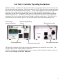
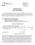
Temperature Control for Research and Industry
LS -120
Lab S afe ty Co ntro lle r
Us e r's Manual
Warranty
J-KEM Scientific, Inc. warrants this unit to be free of defects in materials and workmanship and to give
satisfactory service for a period of 12 months from date of purchase. If the unit should malfunction, it
must be returned to the factory for evaluation. If the unit is found to be defective upon examination by
J-KEM, it will be repaired or replaced at no charge. However, this WARRANTY is VOID if the unit
shows evidence of having been tampered with or shows evidence of being damaged as a result of
excessive current, heat, moisture, vibration, corrosive materials, or misuse. Components which wear or
are damaged by misuse are not warranted. This includes contact points, fuses and solid state relays.
THERE ARE NO WARRANTIES EXCEPT AS STATED HEREIN. THERE ARE NO OTHER
WARRANTIES, EXPRESSED OR IMPLIED, INCLUDING BUT NOT LIMITED TO THE IMPLIED
WARRANTIES OF MERCHANTABILITY AND OF FITNESS FOR A PARTICULAR PURPOSE. IN
NO EVENT SHALL J-KEM SCIENTIFIC, INC. BE LIABLE FOR CONSEQUENTIAL, INCIDENTAL
OR SPECIAL DAMAGES. THE BUYER'S SOLE REMEDY FOR ANY BREACH OF THIS
AGREEMENT BY J-KEM SCIENTIFIC, INC. OR ANY BREACH OF ANY WARRANTY BY J-KEM
SCIENTIFIC, INC. SHALL NOT EXCEED THE PURCHASE PRICE PAID BY THE PURCHASER TO
J-KEM SCIENTIFIC, INC. FOR THE UNIT OR UNITS OF EQUIPMENT DIRECTLY AFFECTED BY
SUCH BREACH.
Service
J-KEM Scientific maintains its own service facility and technical staff to service all parts of the controller,
usually in 24 hours. For service, contact:
J-KEM Scientific, Inc.
6970 Olive Boulevard
St. Louis, MO 63130
(314) 863-5536
FAX (314) 863-6070
Web site: http://www.jkem.com
E-Mail: [email protected]
This manual contains parameters specific to temperature controller Serial #_________________.
When calling with a technical question, please have the controller’s serial number available.
2
Lab Safety Controller Operating Instructions
J-KEM’s Lab Safety Controller (LS-120) combines both an over-temperature limit controller and a coolant
flow monitor in the same instrument. When in operation, the LS-120 allows the user to monitor and control
power to an attached instrument, normally a heater. As long as the temperature of the attached instrument
says below an over-temperature limit, entered by the user, power is applied to the instrument. If the
temperature exceeds the over-temperature limit, power is removed from the attached instrument until the
LS-120 is manually reset. In addition to entering an over temperature limit, the LS-120 can optionally
monitor the flow rate of coolant, typically water, through a condenser or other device. If the flow rate of
water falls below a user set value, power is also removed from the heater until being manually reset.
Thermocouple
sensed temperature
Flow rate programming
selector
Thermocouple input
Instrument power outlet
Mode selection switch
Flow monitor connector
The Lab Safety Controller can be used to monitor just temperature, just coolant flow rate, or both. The
setup procedure for each of these modes is listed below.
Any piece of equipment can be plugged into the power receptacle of the Lab Safety Controller as long as it
draws less than 15 amps @ 120 volts; 1800 watts.
3
Setup for Monitoring Reaction Temperature and Coolant Flow Rate
1.
Setup the controller by:
a)
b)
c)
d)
e)
2.
Turn power to the lab safety controller on.
Connect the flow meter to the flow monitor connector on the back of the controller.
Set the mode selection switch on the back of the controller to “Temp & flow”.
Plug a thermocouple into the thermocouple input and place the thermocouple at the point in the
reactor where you want to measure the temperature of the process.
Plug the heater, or monitored instrument, into the instrument power outlet on the front of the
controller.
Enter the over-temperature limit into the digital meter.
To enter a set point (i.e., the desired temperature).
Hold in the * button and simultaneously press the s
key to increase or the t key to decrease the set point.
The set point can be seen at anytime by holding in
the * key. The set point appears as a blinking
number in the display.
3.
Enter the minimum coolant flow rate by:
a)
b)
c)
d)
e)
4.
Place the flow sensing head on the outlet line of the condenser or whatever piece of equipment the
flow rate is to be monitored in. Note the direction of flow printed on the side of the sensing head.
Set the flow rate programming selector to the “Set” position.
Adjust the flow rate of the coolant through the sensor to the minimum acceptable flow rate.
Turn the flow rate programming selector knob to “RUN” and the green LED (OK) should turn on.
This establishes the current flow rate going through the sensing head as the minimum acceptable
flow rate.
Increase the flow rate of the coolant to the desired level. Note: the flow rate should be increased
some amount above the flow set in Step D, so that a small change in flow rate doesn’t falsely
trigger the monitor.
If the heater, or monitored instrument, has a power switch, turn it on now. Power is applied to the
instrument power outlet on the front of the Lab Safety Controller as long as the flow of liquid going
through the flow sensor stays above the level established in Step 3 and the temperature of the reaction
stays below the limit temperature entered in Step 2.. If flow falls below the entered level, or the
temperature rises above the limit temperature, power is permanently disconnected from the instrument
power outlet. To reset the controller from an alarm state, the controller must be turned off, and then
back on.
4
Setup for Monitoring Reaction Temperature Only
1.
Setup the controller by:
a)
b)
d)
e)
2.
Turn power to the lab safety controller on.
Set the mode selection switch on the back of the controller to “Temp only” position.
Plug a thermocouple into the thermocouple input and place the thermocouple at the point in the
reactor where you want to measure the temperature of the process.
Plug the heater, or monitored instrument, into the instrument power outlet on the front of the
controller.
Enter the over-temperature limit into the digital meter.
To enter a set point (i.e., the desired temperature).
Hold in the * button and simultaneously press the s
key to increase or the t key to decrease the set point.
The set point can be seen at anytime by holding in
the * key. The set point appears as a blinking
number in the display.
3.
If the heater, or monitored instrument, has a power switch, turn it on now. Power is applied to the
instrument power outlet on the front of the Lab Safety Controller as long as the temperature of the
reaction stays below the limit temperature entered in Step 2.. If the temperature rises above the limit
temperature, power is permanently disconnected from the instrument power outlet. To reset the
controller from an alarm state, the controller must be turned off, and then back on.
5
Setup for Monitoring Coolant Flow Rate Only
1.
Setup the controller by:
a)
b)
c)
d)
e)
2.
Turn power to the lab safety controller on.
Connect the flow meter to the flow monitor connector on the back of the controller.
Set the mode selection switch on the back of the controller to “Temp & flow”.
A thermocouple must be connected to the thermocouple input, but it can be left sitting at room
temperature and does not need to be connected to the reaction.
Plug the heater, or monitored instrument, into the instrument power outlet on the front of the
controller.
Enter a high over-temperature limit into the digital meter, this will effectively inactivate the limit
temperature controller.
To enter a set point (i.e., the desired temperature).
Hold in the * button and simultaneously press the s
key to increase or the t key to decrease the set point.
The set point can be seen at anytime by holding in
the * key. The set point appears as a blinking
number in the display.
3.
Enter the minimum coolant flow rate by:
a)
b)
c)
d)
e)
4.
Place the flow sensing head on the outlet line of the condenser or whatever piece of equipment the
flow rate is to be monitored in. Note the direction of flow printed on the side of the sensing head.
Set the flow rate programming selector to the “Set” position.
Adjust the flow rate of the coolant through the sensor to the minimum acceptable flow rate.
Turn the flow rate programming selector knob to “RUN” and the green LED (OK) should turn on.
This establishes the current flow rate going through the sensing head as the minimum acceptable
flow rate.
Increase the flow rate of the coolant to the desired level. Note: the flow rate should be increased
some amount above the flow set in Step D, so that a small change in flow rate doesn’t falsely
trigger the monitor.
If the heater, or monitored instrument, has a power switch, turn it on now. Power is applied to the
instrument power outlet on the front of the Lab Safety Controller as long as the flow of liquid going
through the flow sensor stays above the level established in Step 3. If flow falls below the entered
level, power is permanently disconnected from the instrument power outlet. To reset the controller
from an alarm state, the controller must be turned off, and then back on.
6
Change between Latching / Nonlatching and Deviation High / Low
This controller is initially configured as an Over Temperature Limit (deviation
high). That means the controller turns power ON when below the entered
temperature and OFF when above it. The controller also has a Latching feature
which requires that the power switch be turned off for three seconds and back on
again to reset. The controller will turn OFF power permanently the first time
the reaction reaches the entered temperature.
To change the configuration of the controller :
1-Press and hold both the UP and DOWN arrow buttons of the meter in for three
seconds untill the word “tunE” appears and then let go.
2-Press only the DOWN arrow button once and the word “LEUL 1” will appear.
3-Hold the star(*) button in and at the same time press the UP arrow button once
and the word “LEUL 2” will appear.
4-Press the UP button five times until the word “SP2.A” appears.
5-Change from “dV.hi” (deviation high) to “dV.Lo” (deviation low)
by holding the star (*) button in and at the same time press the UP arrow
button once and the word “dV.Lo” appears.
6-Change from (Latch and Hold) “Lt.ho” to (Nonlatching) “nonE”
Press only the UP button once more and the word “SP2.b” appears.
Hold the star (*) button in and at the same time press the DOWN arrow button
until the word “nonE” appears.
7-Return to normal operation by pressing both the UP and DOWN arrow buttons
in and hold for three seconds until the display goes back to displaying the
current temperature.
7