1
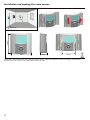
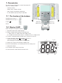
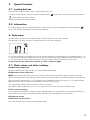
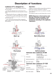
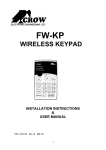
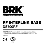
THERMOMATIC EC HOME®
Wireless room sensor – Installation and User Manual
NOTE! This manual is primarily intended for installation and use of the
wireless room sensor for Thermomatic EC Home. Other installations and
functions are explained in the complete manual for EC Home.
Locating the aerial:
Aerials should not be
Aerials should not be
placed on metallic objects located to close ot other
or on metal pipes.
wireless units or power
cables.
Preparation:
Aerials should not be
located too close to
the room unit during
initiation.
110-240 V
3. Fit the flow
sensor
1. Turn off the pump
2. Fit the motor to
the mixing valve
4. Plug in the power
supply
Activation of radio communication:
5. Browse to section 7.10
of the menu
6. Click to start radio
communication
7. Insert the batteries
11. Start the pump
8. Close the cover and hold the
button depressed in order to start
the initiation
ECHOME_WL_Manual_E.indd
821505-E
121026
9. INI will light for some 10. Enter the motor’s direction
of rotation (menu 7.1)
seconds – Ready!
Termoventiler AB
+46 (0)321 - 261 80 • [email protected] • www.termoventiler.se
1
Installation and locating the room sensor:
80 mm
Min 20cm
83mm
27mm
60mm
NOTE! We recommend that you install the room sensor using the enclosed screws and plugs, as incorrect
positioning of the sensor may jeopardize heating comfort.
2
1. Presentation
This room sensor is designed for use with Thermomatic EC
Home (ver. 121001 or later).
-
Anti-frost function
-
Holiday (Timer) / Booster function
-
Keeps settings during battery replacement
-
2 x AAA batteries give up to 2 years‘ operation
1.1 The function of the buttons
Move/browse to the left (<-)
Move/browse to the right (->)
Escape (
)
Edit (•)
Decrease (-)
Increase (+)
Approve (OK)
Status LED
1.2 Display & LED
Green flashing for OK: Approval required
1. Operational mode (active mode displayed).
2. Displays selected control setting or active tool menu.
r = Room sensor, ro = Room sensor with outdoor sensor
or = Outdoor sensor with room sensor, o = Outdoor sensor, C = Supply sensor
3. The icons are displayed when the Tools menu is active and at start-up.
4. The icon that lights shows which relevant temperatures is
shown on the display (Room
or outdoor
.
When displaying the set point, none of the icons light).
3
1
2
5. Battery icon. Flashes when the battery voltage is low.
6. Set or read temperature, and remaining time (if Timer setting is on)
7. Button lock indicator.
8
9
8. RF indicator. Lights during transmission.
5
9. External contact (remote control) activated (in CC).
7
6
4
3
2.
Settings and menu display
- Open the lower cover for access to the navigation buttons (<-) or (->).
- You can now press these buttons to show the row with various operational modes.
Move the cursor to the desired operational mode and press (OK) to set the mode. See below for explanation of the various modes.
What is displayed and settings‘ options:
In order to browse the values use the Escape button
All set values, apart from Timer, can also be set from the Control Panel.
When only using room sensor (mode r) or room sensor + outdoor sensor (mode ro), you can set the desired room temperature
(set point) for Day, Night/Moon or Timer. The display shows the set point, the room temperature, and outdoor temperature if
appropriate.
When using room sensor with outdoor sensor as the priority (mode or) the set room temperature acts as a maximum limit. It
should then be set slightly above the desired room temperature. The display shows the maximum value, the room temperature,
and outdoor temperature.
When only using an outdoor sensor (mode o), no normal temperature settings can be made for the room sensor. If you want to
reduce you can set it using the Night/Moon temperature. It is, however, still possible to select operational modes (apart from
Timer), and you can see the actual indoor and outdoor temperature. All curve settings are made from the Control Panel.
When using only the supply sensor (mode C), you can set the desired supply temperature. You can also see the relevant room
temperature. Potential reduction of the supply temperature can be set using the Night/Moon temperature.
2.1 “Day” temperature
In this mode, the set ”Day” temperature is kept all of the time. The factory settings are 20°C for ”r” and ”ro”, 30°C for ”or” and
60° for ”C”. By pressing (-) or (+), the temperature will begin to flash and the setting may be changed. Save by pressing (OK).
2.2
”Night/Moon” temperature
In this mode, the set ”Night/Moon” temperature is kept all of the time. The factory settings are 16°C for ”r” and ”ro”, 0°C for ”or”, ”o”
and ”C”. By pressing (-) or (+), the temperature will begin to flash and the setting may be changed. Save by pressing (OK).
2.3 Anti-frost mode
This is used if you want to shut down the heating, but still have a minimum permitted supply tempera-ture to prevent the system freezing, e.g. while you are on holiday. The anti-frost temperature is fixed at 10°C.
2.4 Timer mode
Get started guide for settings:
The timer mode means that you can change the temperature at certain times. This is not available for modes ”o” or ”C”.
- You can first set the temperature using (-) or (+). Press (OK) to start the function (preset value is 24°C).
- The next step is to set how many hours “H” (if less than 24 hours) the timer will be active, and then the number of days “d” (up to 45
days) using (-) or (+). Press (OK) to approve.
- The icon starts to flash. Browse using
to see the set point and remaining time.
The room sensor reverts to the previous operational mode after having been in Timer mode. If you want to stop the Timer function
before the end of the period, change to the desired operational mode using (<-) or (>-), and then (OK) to save.
2.5 Auto mode
In this mode, EC Home automatically switches between Day and Night temperatures, according to the time settings on the Control
Panel. The following temperature settings apply when the Auto mode is activated:
Select the temperature to be changed using
. A single press on (-) or (+) will make the set point to be changed/read start to flash,
and this setting can be changed using (-) or (+). The value is saved when you press (OK). The room sensor automatically reverts to the
main menu after a couple of seconds.
NOTE! All time settings are made from menu 4 on the Control Panel. You will find this described in the full
manual for EC Home.
4
3.
Special functions
3.1 Locking buttons
Used to prevent changes to settings, e.g. in a child’s room or public area.
- In order to activate the lock, first press and hold the Escape button (
-
) while at the same time pressing the Edit button (•)
The icon will be shown on the display.
- Repeat the procedure to unlock the buttons.
3.2 Information
This function allows you to see all actual temperatures, and the set values by pressing repeatedly on the Escape button (
).
You can also see time remaining when the Timer mode is activated.
4. Tools menu
The room sensor has a tools menu for other settings. In order to access this menu, press and hold
the Edit button (•) for 3 sec. The menu is activated and the first sub-menu is displayed:
The first menu displayed is the initiation mode. You can select the parameters to be changed using the navigation buttons (<-) or
(>-). When you have selected a parameter, you can edit the value using the (OK) button, or begin to change the value using (-) or
(+). The value flashes for a few seconds or until (OK) is pressed. In order to save the change you must press (OK).
In order to leave the tools menu, browse to « End » and press (OK).
4.1 Basic values and other settings
00 INI: Radio configuration
Sends the radio link signal to pair the room sensor with the Control Panel/aerial.
04 HG: Room sensor calibration
NOTE! The heat inertia of a house means that it may take as long as 24 hours before the right tempera-ture is achieved.
Place a thermometer by the side of the room sensor (around 1.5 m above the floor) and read off the temperature after one hour.
When you enter the calibration menu, ”no” is displayed when no calibration has taken place. Use the (-) or (+) button to set the
temperature to the same as shown on the thermometer. Then press (OK) to accept.
”Yes” should now be displayed and the new value is saved in the memory.
If you need to remove a calibration, press on (-) or (+) when you are in this menu to erase the cali-brated value.
07 Clr: Factory settings
Press and hold the (OK) button for 3 seconds to reset. Settable temperatures and parameters are returned to the factory settings. NOTE! Ensure that you have everything you need to be able to start again before you use this function.
08 Program version
09 End: Exit the Tools menu
Press (OK) to exit the menu and return to the operational mode.
5
5.
Troubleshooting and Solutions
Room sensor does not start
Battery problems
- Check that the plastic tab has been removed from the batteries.
- Check that the batteries have been inserted correctly.
- Check that the batteries are OK.
Battery voltage too low
- icon flashes (Battery)
- Change the batteries.
The room sensor appears to work correctly, but the heating does not work
- Check that the room sensor icon
is lit steadily on the Control Panel display.
- If the icon is not lit: Check the aerial connection.
- If the above is OK, try to change the batteries in the room sensor.
- Contact your electrician.
RF communication does not work
Check the following items:
- The aerial must not be placed nearer than 50 cm to other electrical or wireless units, e.g. GSM or WiFi.
- Aerial should not be placed on metallic objects or too close to metal pipes.
The room sensor appears to work correctly, but the temperature in the room
does not agree with my thermometer
- Try to calibrate the room sensor (see Tools menu 04).
- Contact your electrician/retailer to check whether control needs adjustment/adaptation to your heat-ing system.
6.
Technical specifications
Surrounding environment:
Working temperature:
Transport and storage temperature:
Electrical safety class:
Range:
Precision:
Settings range:
0°C - 40°C
-10°C to +50°C
IP30
Approx. 30 m (in buildings)
0.1°C
Day, Night/Moon, Timer 5°C – 30°C in 0.1°C steps
Supply temperature
5°C – 90°C in 1°C steps
Power supply:
Battery (lifetime ~2 years), 2 AAA LR03 1.5V Alkaline (or equivalent)
Sensor type:
NTC, 10 kOhm at 25°C
Radio frequency: 868 MHz, <10mW
The room sensor has been designed in accordance with the following standards or other standardising documentation:
EN 60730-1 : 2003, EN 61000-6-1 : 2002, EN 61000-6-3 : 2004, EN 61000-4-2 : 2001, EN300220-1/2, EN301489-1/3,
R&TTE 1999/5/EC, Low voltage 2006/95/CE, EMC 2004/108/CE
6