1
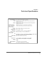
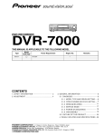
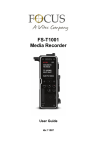
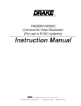
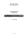
MediaConverter
Model MC-2E
User’s Guide
MANL-1022-03
Notices:
Legal, Regulatory, and Safety
LEGAL
THIS DOCUMENT CONTAINS CONFIDENTIAL AND PROPRIETARY INFORMATION OF
FOCUS ENHANCEMENTS AND ITS RECEIPT OR POSSESSION DOES NOT CONVEY
ANY RIGHTS TO REPRODUCE OR DISCLOSE ITS CONTENTS, OR TO MANUFACTURE,
USE, OR SELL ANYTHING THAT IT MAY DESCRIBE, OR USE IN WHOLE OR IN PART
WITHOUT THE SPECIFIC WRITTEN AUTHORIZATION OF FOCUS ENHANCEMENTS IS
STRICTLY FORBIDDEN.
EVERY EFFORT HAS BEEN MADE TO ENSURE THAT THE INFORMATION IN THIS
DOCUMENT IS COMPLETE AND ACCURATE AT THE TIME OF PRINTING; HOWEVER,
THE INFORMATION CONTAINED IN THIS DOCUMENT IS SUBJECT TO CHANGE.
Copyright
Copyright 2006 Focus Enhancements
All Rights Reserved
The material contained in this document is protected by copyright laws of the United States of
America and other countries. It may not be reproduced or distributed in any form by any
means, altered in any fashion, or stored in a database or retrieval system, without the
express written permission of FOCUS ENHANCEMENTS.
Contacting FOCUS ENHANCEMENTS
Office Hours:
Monday through Friday
8:00 AM to 5:00PM (Central Time)
Email:
[email protected]
Telephone:
763-398-1658
Fax:
763-571-7688
Address
Focus Enhancements, Inc.
1370 Dell Avenue
Campbell, CA. 95008
MediaConverter MC-2E User’s Guide
i
Serial Number
The serial number for this equipment is located on the bottom of the unit. Please write this
serial number on the enclosed warranty card and keep it in a secure area.
Registering Products, Technical Support, and Warranty
To register a Focus Enhancements product use the online form at:
http://www.focusinfo.com/rfi/warranty.asp.
For questions about technical support or warranty, contact the seller, distributor, or contact
Focus Enhancements by email: [email protected].
Unauthorized Use
Focus Enhancements is not responsible for the unauthorized use of its equipment and
will not make allowance or credit for unauthorized use or access.
Unauthorized Alterations and Modifications
Alterations or modifications to Focus Enhancements equipment or software that is
carried out without appropriate authorization may invalidate the product warranties and
the user's right to operate the equipment.
Unauthorized Servicing
Do not attempt to service this product yourself. Opening or removing covers may expose
dangerous voltage or other hazards.
Refer all servicing to qualified service personnel.
Returning Materials
End Users
If the MC-2E was not purchased directly from Focus Enhancements, it is necessary to
contact the seller and determine what procedure is needed for repairing the converter.
Direct Sales
(VARs, Distributors, and Corporate Customers
If the MC-2E has problems that cannot be corrected over the telephone by Focus
Enhancements technical support, it may be necessary to return the converter to Focus
Enhancements.
MediaConverter MC-2E User’s Guide
ii
To contact Focus Enhancements:
Office Hours:
Monday through Friday
8:00 AM to 5:00PM (Central Time)
Email:
[email protected]
Telephone:
763-398-1658
Fax:
763-571-7688
Address:
Focus Enhancements, Inc.
1370 Dell Avenue
Campbell, CA. 95008
www.focusinfo.com
All materials shipped back to Focus Enhancements must be accompanied by a Return
Materials Authorization (RMA) number. Contact Focus Enhancements Technical
Support to receive a RMA number.
Write the RMA number clearly on the shipping label.
FIGURE 1. Focus Enhancements Mailing Label
Regulatory and Safety
Environmental Precaution
Focus Enhancements, Inc.
1370 Dell Avenue
Campbell, CA. 95008
Model Number: MediaConverter MC-2E
Date of Manufacture:
Reference the Serial Number label attached to the unit.
MediaConverter MC-2E User’s Guide
iii
FCC Class A
This product satisfies FCC regulations when shielded cables and connectors are used to
connect the unit to other equipment. To prevent electromagnetic interference with electric
appliances such as radios and televisions, use shielded cables and connectors.
This equipment has been tested and found to comply within the limits for a Class A digital
device, pursuant to Part 15 of the FCC Rules. These limits are designed to provide
reasonable protection against harmful interference in a residential installation. This
equipment generates, uses, and can radiate radio frequency energy and, if not installed and
used in accordance with the instructions, may cause harmful interference to radio
communications. However, there is no guarantee that interference will not occur in a
particular installation. If this equipment does cause harmful interference to radio or television
reception, which can be determined by turning the equipment off and on, correct the
interference by one or more of the following:
•
Reorient or relocate the receiving antenna.
•
Increase the separation between the equipment and receiver.
•
Connect the equipment to an outlet on a circuit different from that used by the receiver.
•
Consult the dealer or an experienced radio/TV technician for help.
Symbols
In the MC-2E Unit
This symbol indicates the presence of an uninsulated Dangerous
Voltage within the product’s enclosure that may constitute a risk of
electric shock to persons.
In the MC-2E Documentation
This symbol indicates important information.
This symbol indicates information about features, functions,
operations, that is of interest to the user.
MediaConverter MC-2E User’s Guide
iv
Documentation
This manual is written with the assumption that the user is familiar with analog and
digital video/audio signals and hardware.
Read, Retain, and Follow Instructions
All the safety and operating instructions should be read before the product is operated.
•
Retain Documentation
Place documentation in a secure place for future reference on operating and
safety instructions.
•
Follow All Operating and Safety Instructions
•
Pay Attention to All Warnings
Warnings are provided to protect the operator, the equipment, and content.
Electrical Precautions
Do Not Expose to Moisture
Do not use this product near water or in an environment where it is exposed to
dampness or there is the possibility of it getting wet.
Do Not Remove Cover
There are No User Serviceable Parts inside this unit. Servicing should be done by
qualified service personnel.
ON / OFF Switch in Stand-By Position
The On/Off switch Does Not Separate the Unit From the Main Power when it is in the
stand-by position.
Power Sources
Use only power sources that match those indicated on the marking label. If unsure of
the type of power supply that is available, consult your dealer or local power company.
Do Not Overload Power Outlets
Do not overload wall outlets, extension cords, or integral convenience receptacles as
this can result in a risk of fire or electric shock.
Verify Power Plugs are Fully Inserted
To prevent potential electrical shock to personnel, verify that the MC-2E power cord
plug is fully inserted into a grounded receptor and that the plug blades are not exposed.
ATTENTION
POUR PREVENIR LES CHOCS ELECTRIQUES NE PAS UTILISER CETTE FICHE
POLARISEE AVEC UN PROLONGATEUR, UNE PRISE DE COURANT OU UNE
AUTRE SORTIE DE COURANT, SAUF SI LES LAMES PEUVENT ETRE INSEREES A
FOND SANS EN LAISSER AUCUNE PARTIE A DECOUVERT.
MediaConverter MC-2E User’s Guide
v
Power-Cord Protection
•
Routing Power-Cords
Route power supply cords so that they are not likely to be walked on or pinched by
items placed upon or against them. Avoid sharp angles in the cord, particularly at
plugs, convenience receptacles, and the point where they exit the product.
•
Non-Use Period
During extended periods when the device is not used, unplug it from the power
source and retract the power-cord.
Grounding or Polarization
•
Polarized
If this product is equipped with a polarized alternating current line plug (a plug
having one blade wider than the other), it will fit into the outlet only one way. This is
a safety feature. If you are unable to insert the plug fully into the outlet, try
reversing the plug. If the plug should still fail to fit, contact your electrician to
replace your obsolete outlet. Do not defeat the safety purpose of the polarized
plug.
•
Grounded
If this product is equipped with a three-wire grounding type plug, a plug having a
third (grounding) pin, it will only fit into a grounding type power outlet. This is a
safety feature. If you are unable to insert the plug into the outlet, contact your
electrician to replace your obsolete outlet. Do not defeat the safety purpose of the
grounding type plug.
Outdoor Antenna Grounding
If an outside antenna or cable system is connected to the MC-2E, verify that the
antenna or cable system is grounded. This provides some protection against voltage
surges and built-up static charges.
Refer to Article 810 of the National Electric Code, ANSI/NFPA 70, for information about
the proper grounding of the mast and supporting structure, grounding of the lead-in wire
to an antenna discharge unit, size of grounding connectors, location of antenna
discharge unit, connection to grounding electrodes, and requirements for the grounding
electrode. See Fig. A.
Lightning and Power Surges
During electrical storms or when left unattended and unused for long periods of time,
unplug the MC-2E from the power source and disconnect the antenna or cable system.
MediaConverter MC-2E User’s Guide
vi
Power Lines
Do not locate an outside antenna system in the vicinity of overhead power lines, electric
light or power circuits, or where it can fall onto such lines or circuits.
When installing an outside antenna system, extreme care should be taken to keep from
touching such power lines or circuits as contact with them might be fatal.
Optical Precaution
The use of optical instruments with this device will increase hazards to the eyes hazard.
Maintenance and Moving
Cleaning
Unplug this product from the wall outlet before cleaning. The product should be cleaned
only with a polishing cloth or a soft dry cloth. Never clean with furniture wax, benzine,
insecticides or other volatile liquids since they may corrode the cabinet.
Servicing
Unplug the device from the power outlet and refer servicing to qualified service
personnel under the following conditions:
•
When the power-supply cord or plug is damaged.
•
If liquid has been spilled, or objects have fallen into the product.
•
If the product has been exposed to rain or water.
•
If the product does not operate normally when following the operating instructions.
Adjust only those controls that are covered by the operating instructions. The
incorrect adjustment of other controls can result in damage and often requires
extensive work by a qualified technician to restore the product to its normal
operation.
•
If the product has been dropped or damaged in any way.
•
When the product exhibits a distinct change in performance.
Accessories and Replacement Parts
Use only attachments and accessories recommended by Focus Enhancements.
Use only replacement parts specified by the Focus Enhancements or of comparable
quality and characteristics as the original parts.
Unauthorized substitution of parts can result in fire, electrical shock, other hazards, and
loss of warranty.
Safety Check
Upon completion of any service or repairs to this product, ask the service technician to
perform safety checks to determine that the product is in proper operating condition.
MediaConverter MC-2E User’s Guide
vii
Operating Environment
Location
Install this device on a sturdy, level surface, away from moisture and dust.
•
Heat
Locate this device away from heat sources such as radiators, heat registers,
stoves or other electrical devices (including amplifiers) that generate heat.
•
Wall or Ceiling Mounts
This device should not be mounted to a wall or ceiling.
Any mounting of this device should follow its instructions, and should use only mounting
accessories recommended by Focus Enhancements.
Ventilation
Do not block the ventilation openings in the MC-2E cabinet. Overheating can occur and
damage the device. Do not place this device in a built-in installation, such as a
bookcase or rack, unless proper ventilation is provided.
MediaConverter MC-2E User’s Guide
viii
Table of Contents
CHAPTER 1
Introduction . . . . . . . . . . . . . . . . . . . . . . . . . . . . . . . . 1
Unpacking the MC-2E
........................ 2
Connecting the MC-2E . . . . . . . . . . . . . . . . . . . . . . . . 3
CHAPTER 2
LCD and Front Panel Controls . . . . . . . . . . . . . . . .
Menu Display and Navigation . . . . . . . . . . . . . . . . . . .
Reset MC-2E to Factory Defaults . . . . . . . . . . . . . .
Control Menus . . . . . . . . . . . . . . . . . . . . . . . . . . . . . .
CHAPTER 3
IEEE-1394 (FireWire) Interface
...............
PAL and NTSC MC-2Es . . . . . . . . . . . . . . . . . . . . . .
Betacams and other VTRs . . . . . . . . . . . . . . . . . .
PCs with NLE . . . . . . . . . . . . . . . . . . . . . . . . . . . .
Connecting a MC-2E to a Windows PC . . . . . . . . . .
Connecting Multiple MC-2Es . . . . . . . . . . . . . . . . . .
11
11
11
11
12
12
CHAPTER 4
RS-232 Interface . . . . . . . . . . . . . . . . . . . . . . . . . . .
Connecting a PC and MC-2E via RS-232 Port . . . . .
Cabling and Pinout. . . . . . . . . . . . . . . . . . . . . . . . . .
Communications . . . . . . . . . . . . . . . . . . . . . . . . . .
Operation . . . . . . . . . . . . . . . . . . . . . . . . . . . . . . . . .
Data format . . . . . . . . . . . . . . . . . . . . . . . . . . . . . . . .
Writing Data to the MC-2E . . . . . . . . . . . . . . . . . . . .
Receive from the MC-2E . . . . . . . . . . . . . . . . . . .
Read Data from the MC-2E . . . . . . . . . . . . . . . . .
Examples of Write and Read Commands
......
RS-232 Commands . . . . . . . . . . . . . . . . . . . . . . . . .
Command Groups . . . . . . . . . . . . . . . . . . . . . . . .
Video (0x01) . . . . . . . . . . . . . . . . . . . . . . . . . . . . .
Audio (0x02) . . . . . . . . . . . . . . . . . . . . . . . . . . . . .
DV Format (0x03) . . . . . . . . . . . . . . . . . . . . . . . . .
Misc (0x05) . . . . . . . . . . . . . . . . . . . . . . . . . . . . . .
13
13
13
13
14
14
14
15
15
16
16
16
17
18
18
18
5
5
6
6
MediaConverter MC-2E User Manual
ix
CHAPTER 5
RS-422 Interface . . . . . . . . . . . . . . . . . . . . . . . . . . . .19
Supported TC Formats
. . . . . . . . . . . . . . . . . . . . . . .19
Supported Editing Suites . . . . . . . . . . . . . . . . . . . .20
NLE Setup . . . . . . . . . . . . . . . . . . . . . . . . . . . . . . .21
Adobe Premiere Pro 2.0 . . . . . . . . . . . . . . . . . . . .21
Avid XPress DV 3.5.4 or higher . . . . . . . . . . . . . .21
CHAPTER 6
Technical Specifications
MediaConverter MC-2E User Manual
x
. . . . . . . . . . . . . . . . . . . . .23
MediaConverter MC-2E User Manual
xi
MediaConverter MC-2E User Manual
xii
CHAPTER 1
Introduction
Thank you for purchasing the Focus Enhancements MediaConverter MC-2E.
The MC-2E is a format converter that bridges the gap between analog and digital audio/video
formats. The MC-2E supports all major professional and consumer Video and Audio In- and
Output Formats.
This rack-mountable box features analog video and audio I/O (balanced and unbalanced),
digital video (SDI), and digital audio (AES/EBU) support, and standard DV /DV CAM over
the FireWire (IEEE 1394) interface. Also, the MC-2E can convert Composite or S-Video (Y/
C) signals to Component (YUV) and vice versa.
The MC-2E supports embedded SDI audio, i.e. audio inserted in the SDI stream as ancillary
data, for both SDI input and output. This allows a single cable to carry both video and audio
signals. On the MC-2E, the first four stereo pairs, of the SDI input, are selectable as an audio
input source. The SDI output always contains the selected audio stereo input in the first
stereo pair of the SDI stream.
SMPTE 272M Definition for Embedded Audio
Embedded audio, defined in the SMPTE 272M spec, contains up to 16 channels of up to 20-bit
audio data sampled at 48 kHz. The audio-sampling clock is locked to the video signal. These 16
channels are selectable in stereo pairs for a total of 8 available stereo pairs.
In addition, the MC-2E has Genlock functionality that permits the seamless integration of the
system into a professional studio environment.
MediaConverter MC-2E User’s Guide
1
Introduction
1.1 Unpacking the MC-2E
Unpack the MC-2E and verify that all components are present and not damaged.
Missing or Damaged Components
If there are missing or damaged items, contact Focus Enhancements Support for assistance.
Email: [email protected]
Telephone: 763-398-1658
The standard MC-2E system includes:
•
•
•
•
•
•
MediaConverter MC-2E unit
AC Adapter, 12V, 1A with power cord
DV Cable, 4-pin to 6-pin, 6 ft. (1.8 m)
Mounting Brackets (2), 19 in., screws (4)
Rubber Feet (4)
MediaConverter MC-2E User’s Guide
MediaConverter MC-2E User’s Guide
2
Connecting the MC-2E
1.2 Connecting the MC-2E
Controls
Power
On / Off
LCD
Display
Menu Controls
Next
+
Front View
In
Out
Audio Unbalanced
(RCA Connectors)
Out
In
S-Video, Y/C
(4-pin Mini DIN Connectors)
Input/Output
DV/DVCAM
(6-pin, FireWire
IEEE-1394)
Out
In
Composite Video, CVBS
(BNC Connectors)
RS232
(Sub D, 9-pin,
Female Connector)
SDI Video
(BNC Connectors)
In Out
Rear View
Input/Output
DV/DVCAM
(6-pin, FireWire
IEEE-1394)
Out
In
Genlock
External Reference Sync,
(BNC Connectors)
DV Settings
Switch 1: NTSC, PAL
Switches 2-4: Unit IDs 0-7
(Dip Switch)
Out In
AES/EBU
Digital Audio
(XLR Connectors)
Out
In
Analog Components
Y U/B-Y V/R-Y
(BNC Connectors)
Input
Left Right
Balanced Audio
(XLR Connectors)
Output
Left Right
Balanced Audio
(XLR Connectors)
RS422
(Sub D, 9-pin,
Female Connector)
1. Connect PC or video/audio equipment.
For details about the IEEE-1394 interface, refer to IEEE-1394 (FireWire) Interface on
page 11.
For details about the DV Settings dip switch, refer to Connecting a MC-2E to a
Windows PC on page 12.
For details about the RS-232 interface, refer to RS-232 Interface on page 13.
For details about the RS-422 interface, refer to RS-422 Interface on page 19.
Do Not Power Up the MC-2E or any attached PCs or video/audio equipment
until all connections have been made.
2. Power on devices in the following order:
• PC
• Video/Audio equipment
• MediaConvertor
MediaConverter MC-2E User’s Guide
3
MediaConverter MC-2E User’s Guide
4
CHAPTER 2
LCD and Front Panel Controls
Use the front Power Switch to power on the MC-2E. The three Menu Control buttons and the
LCD panel are used to manually control the MC-2E unit.
LCD Menu Display
Display consists of two lines.
Function Title
Selected Parameter (value)
Power
On/Off
Menu Controls
Next advances to next functions.
and moves backward and forward
through the parameters (values).
2.1 Menu Display and Navigation
The LCD display has two lines of text.
• Function Title appears on the top line and indicates the function of that screen.
• Parameter (value) appears on the bottom and is a value that may be selected for the
function shown in the top line.
Press Next to advance through the functions, i.e. the top line of the display.
Press either - or + to cycle through the various parameters (values) available for that
particular function. The value displayed in the menu screen is the active value. Whatever
value shown in the display when the menu function changes is the value saved. The saved
value is used until it is changed.
The MC-2E stores its last settings and, should the unit be powered down, uses them when it
powers up.
MediaConverter MC-2E User’s Guide
5
LCD and Front Panel Controls
2.1.1
Reset MC-2E to Factory Defaults
To reset the MC-2E to its factory default settings
press the Next and + buttons at the same time.
The front panel LCD displays the message:
2.2 Control Menus
Menu Displays
Settings and Notes
Only occurs during initialization of MC-2E.
Only occurs during initialization of MC-2E.
Occurs during initialization of MC-2E and when
the system changes DV Direction.
Decode - factory default
Encode
Only Available in DV Encode Mode
Select the type of DV encoding.
CVBS - factory default
Y/C
Y/U/V
SDI, SMPTE259M-C
CVBS ov. rear Y
Only Available in DV Encode Mode
Select the type of DV encoding.
Unbalanced - factory default
Balanced
AES / EBU
SDI emb. Ch 12
SDI emb. Ch 34
SDI emb. Ch 56
SDI emb. Ch 78
Selects Audio Samplerate during DV Encoding
mode.
Shows Audio Samplerate for DV Decoding
mode.
32kHz / 12-bit
48kHz / 16-bit - factory default - Only for DV out
- the internal Samplerate is always 48kHz / 20bits.
MediaConverter MC-2E User’s Guide
6
Control Menus
Menu Displays
Settings and Notes
Only available in DV Decoding mode.
Select the Audio Channel during decoding in DV
Decoding Mode at 32kHz / 12-bits.
Channel A - factory default
Channel B
Select video standard.
PAL - factory default Europe
NTSC - factory default US
NTSC Japan
Off - factory default
Automatic det.
Off - frame sync is free running as time base
corrector.
Automatic detection - unit switches automatically
between time base corrector mode or frame sync
mode.
Select DV/DVCam as DV System.
NTSC 4:1:1 sampling
PAL 4:2:0 sampling
Select the sync/source the unit is connected to.
DV Deck - factory default
Win98/XP, MacOSX
Windows 2000
Use Win98/XP, MacOSX for all three OS.
On
Off - factory default
Use On to access additional menus.
Only available in Menu Expert mode.
On
Off - factory default
On - the DVCodec switches its direction
depending on the incoming NLE application’s
control command.
Play switches the direction to Encode.
Encode activated by Play, Pause, Shuttle
RW, Shuttle FW, Frame advance, and
Frame reverse.
Stop switches to decode.
Decode activated by Stop, Fast Forward,
Rewind, Record, Record Pause.
Off - all direction settings must be entered
manually.
MediaConverter MC-2E User’s Guide
7
LCD and Front Panel Controls
Menu Displays
Settings and Notes
Only available in Menu Expert mode.
RS-422 - factory default
Time code source when in DV Encoding Mode.
If a VTR is connected via RS-422, its time code
is translated into DV time code.
If no VTR is connected, the time code is free
running.
Only available in Menu Expert mode.
DV - factory default
When receiving AV/C commands via Firewire,
they are translated into RS-422 commands.
Only available in Menu Expert mode.
0 - factory default
± 127 (increments between 0 and 127)
When in Studio Genlock mode, set the value for
the horizontal delay between the genlock source
and video output.
Only available in Menu Expert mode.
0 - factory default
± 7 (increments between 0 and 7)
When in Studio Genlock mode, set the value for
the vertical delay between the genlock source
and video output.
Only available in Menu Expert mode.
75 Ohms - factory default
High-Z
Set the termination of the genlock input to either
75 Ohms or High-z. This is necessary, when the
genlock signal is routed to more than one unit.
Only available in Menu Expert mode.
SMPTE/EBU - factory default EU
Betacam - factory default U.S.
MII
Select the level format of the component input.
Only available in Menu Expert mode.
SMPTE/EBU - factory default EU
Betacam - factory default U.S.
MII
CVBS, Y/C rear
Select the level format of the component output.
MediaConverter MC-2E User’s Guide
8
Control Menus
Menu Displays
Settings and Notes
Only available in Menu Expert mode.
0dB - factory default
-14dB ... +4dB
(increment between -14db and 4dB).
Simultaneously select the Audio output level for
all audio output.
MediaConverter MC-2E User’s Guide
9
MediaConverter MC-2E User’s Guide
10
CHAPTER 3
IEEE-1394 (FireWire) Interface
The MC-2E’s EEE-1394, FireWire, Interface provides the ability to attach the
converter to a computer, either a Windows PC or MAC.
There are two 6-pin IEEE-1394 ports on the MC-2E: one on the front panel and one
on the back.
3.1 PAL and NTSC MC-2Es
The MC-2E is available in either PAL or NTSC versions.
3.1.1
Betacams and other VTRs
When using a PC to transcode video signals from a VTR, such as a Betacam, to a
DV VTR or vice versa, select the desired video standard using the LCD and menu
control buttons on the front panel, refer to ”LCD and Front Panel Controls” on
page 5.
3.1.2
PCs with NLE
During the initialization of the DVCodec, the IEEE-1394 configuration ROM is set
to either PAL or NTSC, depending on the setting of the dip switch 1 on the back of
the MC-2E. If the dip switch is not set to match the Videonorm being used, some
NLEs will not work.
NTSC
PAL
MediaConverter MC-2E User’s Guide
11
IEEE-1394 (FireWire) Interface
3.2 Connecting a MC-2E to a Windows PC
These instructions are for PCs equipped with an OHCI compatible IEEE 1394, Firewire,
interface.
1. Connect the DV Interface of the MC-2E to the PC using the 4-pin to 6-pin IEEE-1394
cable provided with the MC-2E.
2. Power On both the PC and MC-2E.
The Windows PC recognizes the MC-2E as new attached hardware and, depending on
the Windows OS, lists it as a Generic Device. The device listing is located in the Windows Device Control screen.
3. Set the DV OS mode.
• Go to the DV Mode / OS menu.
• Choose the mode setting:
Win 98/XP, Mac OSX,
Windows 2000,
DV Deck,
3.3 Connecting Multiple MC-2Es
Multiple MC-2Es can be connected to a PC through the FireWire interface. Each media
converter must have a unique unit ID, 0 through 7. These IDs are set using the dip switches
2, 3, and 4 on the back panel.
ID
2
3
4
0
Off
Off
Off
1
On
Off
Off
2
Off
On
Off
3
On
On
Off
4
Off
Off
On
5
On
Off
On
6
Off
On
On
7
On
On
On
MediaConverter MC-2E User’s Guide
12
CHAPTER 4
RS-232 Interface
The RS-232 interface provides the ability to:
• Directly control the MC-2E using a Terminal program such as HyperTerminal and the
MC-2E’s RS-232 Command Set,
• Update the MC-2E’s firmware,
4.1 Connecting a PC and MC-2E via RS-232 Port
4.1.1
Cabling and Pinout
To connect directly to the MC-2E via the RS-232 PORT, use a one-to-one cable with
a female connector for the PC side and a male connector for the MC-2E side. The
pinning of the cable is as follows:
4.1.2
PC
MC-2E
Signal
2
2
RXD
3
3
TXD
5
5
GND
Communications
Baud Rate
57600
8-bit
1 stop bit
no parity
MediaConverter MC-2E User’s Guide
13
RS-232 Interface
4.2 Operation
Using RS-232 commands, it is possible to read back the settings stored in the
MC-2E. The MC-2E stores parameters in the non-volatile storage which preserves
them in the case of power off and allows their use at power on.
• The commands sent via RS232 override the current MC-2E front panel control
settings.
• Parameters set through the front panel controls override the parameters
previously entered via the RS232 interface.
• Firmware upgrades via RS232 do not change these settings.
4.3 Data format
Values in this section are in decimal with hexadecimal values shown as 0xAA or similar.
4.3.1
Writing Data to the MC-2E
The data format is as follows:
Write (MC-2E)
Start
Command Group
Command
Data
Checksum
Start byte: 0xAA.
Command Group
Command
Data Value
Checksum (Command Group + Command + Data) logical anded with 0xFF.
• Checksum for data transfer is the total of the Command Group, Command, and
Data bytes.
• Overflow or carry bits are ignored.
MediaConverter MC-2E User’s Guide
14
Data format
4.3.2
Receive from the MC-2E
The data format is as follows:
Receive (MC-2E)
Start
Command Group
Command
Data / Return
Checksum
Start byte: 0xAA.
Command Group
Command
Data Values
Checksum (Command Group + Command + Data) logically anded with OxFF.
•
•
•
•
The checksum is the total of the byte values received.
Overflow or carry bits are ignored.
The MC-2E returns the data as it was sent for verification by the Host.
If the MC-2E receives a command requesting a status, time code, or other
parameter value, it returns the value using the data byte position.
• If the MC-2E receives only a command that does not request any information,
the MC-2E returns the original command value.
• If the MC-2E receives a command that is not implemented or is out of range, it
returns 0xFF.
4.3.3
Read Data from the MC-2E
The data format is as follows:
Read (MC-2E)
Start
Command Group
Command
Data
Checksum
Start byte: 0xAA.
Command Group
Command
Data
Checksum (Command Group + Command + Data) logical anded with 0xFF.
• MC-2E reads back the data as it was sent for control purposes. If the command
value requests a status or time code or other value, the data byte contains this
value.
• The MC-2E returns 0xFF as return value, if the command is invalid or the data
is out of range.
• Checksum for data read is the total of the Command Group, Command, and
Data bytes.
• Overflow or carry bits are ignored.
MediaConverter MC-2E User’s Guide
15
RS-232 Interface
4.3.4
Examples of Write and Read Commands
Write a Video Contrast Value 32
Write
0xAA 0x01 0x02 0x20 0x23
Receive
0xAA 0x01 0x02 0x20 0x23
Read Back a Video Contrast Value
Read
0xAA 0x81 0x02 0x00 0x83
Receive
0xAA 0x81 0x02 0x20 0xXX
4.4 RS-232 Commands
4.4.1
Command Groups
Group
Name
description
0x01
Video
Video input/output setting
0x81
Video Read
0x02
Audio
0x82
Audio Read
0x03
DV Format
0x83
DV Format Read
0x05
Misc
0x85
Misc Read
MediaConverter MC-2E User’s Guide
16
Audio input/output settings
DV Format settings
Miscellaneous settings
RS-232 Commands
4.4.2
Video (0x01)
Command
Name
Range
Read Value
(0x81)
Default
0x02
Contrast
0
255
0
255
128
0x03
Saturation
0
128
0
128
64
0x04
Hue / degrees
0x06
Video Input
0 = CVBS
1 = Y/C
2 = YUV
3 = SDI
4 = CVBS over rear Y
0x07
Video System
0 = PAL
1 = NTSC
2 = NTSC Japan
0x09
H-Offset / pixels
-127
0x0A
V-Offset / lines
-7
7
0x0B
Genlock
0x0C
YUV Level
In For-mat:
SMPTE, Betacam,
MII
127
0
0
4
0
0
2
0
127
0
-7
7
0
0 = Off
1 = On
0
1
0
0 = SMPTE
1 = Betacam
2 = MII
0
2
0
-127
127
-127
127
-127
0x0D
75 Ohm Genlock
0 = Off
1 = On
0
1
1
0x0E
YUV Level
Out For-mat:
0 = SMPTE
1 = Betacam
2 = MII
3 = CVBS over rear Y
0
3
0
SMPTE, Betacam,
MII
MediaConverter MC-2E User’s Guide
17
4.4.3
Audio (0x02)
Command
4.4.4
Range
Unbalanced
Balanced
AES / EBU
SDI, Channel 12
SDI, Channel 34
SDI, Channel 56
SDI, Channel 78
Read Value
(0x82)
Default
0x01
Audio Input
0=
1=
2=
3=
4=
5=
6=
0x02
Analog Audio Out
(dB)
0 = +4dB
4 = 0dB
18 = -14dB
0x08
Sample rate
0 = 48kHz /16 bit
3 = 32kHz /12 bit
0, 3
0
0x09
Channel Decoding
Selection
(32kHz / 12 bit)
0 = Channel A
7 = Channel B
0, 7
0
0
6
0
0
18
4
DV Format (0x03)
Command
4.4.5
Name
Name
Range
0x01
DV System
1 = DV/DVCAM
0x02
DV Mode / OS
0 = DV Deck
1 = Win 98/XP, Mac OSX
2 = Win2000
0x03
Mode select
0 = Manual
1 = Automatic on AV/C
command
Read Value
(0x83)
Default
1
1
0
2
0
0, 1
0
Read Value
(0x85)
Default
Misc (0x05)
Command
Name
Range
0x01
Working Mode
0 = DV Decode
1 = DV Encode
0, 1
0
0x02
LCD Backlight
0 = Off
1 = On
0,1
1
• Misc commands are global to the MC-2E.
MediaConverter MC-2E User’s Guide
18
CHAPTER 5
RS-422 Interface
The MC-2E RS-422 Interface provides the ability to control a VTR that conforms to
the Betacam protocol and employs the NLE file system. Combined with the IEEE1394, FireWire interface, these features eliminate the need for an extra RS-422 port
on the host computer.
5.1 Supported TC Formats
When connected to RS-422 device, the MC-2E continuously attempts to read the timecode
from the attached device. The timecode format may be:
•
•
•
•
LTC,
VITC,
interpolated LTC,
interpolated VITC.
When the MC-2E successfully reads the timecode, an * is
shown in the lower right corner of the display. This symbol
indicates that the attached RS-422 device is available and
can be controlled from the PC via the MC-2E’s IEEE-1394
interface. Refer to the list of commands on the following
page.
MediaConverter MC-2E User’s Guide
19
RS-422 Interface
All mandatory Firewire FCP AVC Commands are translated into RS422 commands:
Command
Comment
0.2x
0.2x
10x
10x
Stop, Record, and Record Pause Automatically Switch Converter to Decode
The Stop, Record, and Record Pause commands switch the MC-2E to Decode mode. All
other commands switch the converter to Encode mode. To turn off this feature, set the
DV Dir. Autom. to OFF.
5.1.1
Supported Editing Suites
The Commands are tested to work with the following edit suites on a PC:
•
•
•
•
•
Adobe Premiere Pro 2.0
Avid XPress DV 3.5.4 or higher
Canopus Storm Edit
Canopus Edius
Ulead software - batch digitizing is not implemented
Various Editing Suites May Interpret Timecode Differently
The timecode, which is inserted in the DV data stream and can be read via the editing
software, may have a difference of up to two frames from the original timecode of the RS422
device. The average difference is from zero to one frame.
MediaConverter MC-2E User’s Guide
20
Supported TC Formats
5.1.2
NLE Setup
5.1.2.1 Adobe Premiere Pro 2.0
• Before starting Premiere, the DV-1394Pro SDI should be set to its
working settings: DV Encode/Decode Working Direction or the right
OS setting.
• Do Not Switch the Converter Off and On when Premiere is open.
• In Windows, Record Settings, Device Control Options select the
manufacturer Focus Enhancements and the deck as Standard. For
details, refer to Connecting a MC-2E to a Windows PC on page 12.
• Set Preroll to 5 seconds.
• Timecode-Offset should be set to 0 or 4 1/4 Frames.
Test the value on the system to insure it is the best choice.
• Lock the deck and the MediaConverter to the same external sync.
5.1.2.2 Avid XPress DV 3.5.4 or higher
• Before starting AVID, the MediaConverter should be set to its working
settings, e.g. Encode/Decode Working direction and the correct DV
Mode / OS setting.
• Do Not Switch the MediaConverter Off and On when AVID XPress DV
is open. This may cause problems re configuring the attached unit’s
driver.
• Disable the Firewire Control in the Deck Configuration, when
controlling the VCR through RS-422 directly from AVID via a serial
cable connected to the PC/MAC.
To disable, delete the Deck on the Firewire OHCI channel.
In addition, manually set conversion direction directly at the converter.
This must also be done, when using no deck control.
Set DV Dir. Automat, in the MediaConverter Expert Menu to OFF, refer
to Control Menus on page 6.
• During digital cut or previewing clips in the bin, the Record Tool
Window must be closed. Otherwise AVID XPress experiences a delay
of up to 5 seconds before the playback starts.
• Set desktop play delay to 13-15 frames for PAL.
Test this setting, it is affected by the speed of the computer.
• Verify that the direction of the Audio channels in the Audio Tools of
AVID XPress matches Record, Preview, or Digital Cut requirements.
Record = Input
Preview = Output
Digital Cut = Output.
• Set the Toggle Video Out Button (above the Timeline) to blue (OFF).
MediaConverter MC-2E User’s Guide
21
MediaConverter MC-2E User’s Guide
22
CHAPTER 6
Technical Specifications
AUDIO, Analog
Audio Sampling
Input
Output
48 or 32 kHz, 20-bit resolution, 2-channel
Balanced: XLR (2), +4 dBu nominal, 20 k Ohm input impedance,
Unbalanced: (RCA x 2)
Balanced: XLR (2), +4dBu nominal into 600 Ohm load impedance,
Unbalanced: (RCA x 2)
AUDIO, Digital I/O
AES/EBU: XLR (2), 2-7 V p-p across a 110 Ohm load
SYNC, Audio/Video
Audio and Video fully synchronized for all input sources.
VIDEO, Analog
Formats
Composite I/O
S-Video I/O
Component I/O
NTSC, 525 line / 60Hz or PAL, 625 line / 50Hz,
BNC, 75 Ohm, 1.0V p-p,
4-pin Mini DIN, 75 Ohm, Y: 1.0V p-p, C: 627mV p-p
BNC (3), 75 Ohm, (Y, R-Y, B-Y), SMPTE level
VIDEO, Digital
I/O
DV/DV CAM
SDI: (BNC x 2), 75 Ohm, 10-bit resolution, 270 MBit/sec, SMPTE 259M
SDI: Supports embedded audio for both SDI in and out
IEEE-1394, FireWire, 6-pin ports (2)
PHYSICAL
Dimensions
Weight
Mounting Option
POWER
17 1/4 in. (width) x 1 7/8 in. (height) x 6 1/8 in. (depth)
440 mm (width) x 45 mm (height) x 155 mm (depth)
3.3 lbs.
1.5 kg
1U, detachable, rack-mount brackets
12V, 15W DC, self-locking, 3-pin connection
MediaConverter MC-2E User’s Guide
23
MediaConverter MC-2E User’s Guide
24
MediaConverter MC-2E User’s Guide
MANL-1022-03