1
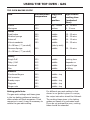
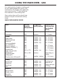
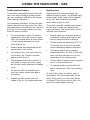
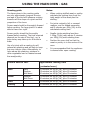
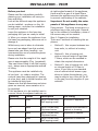
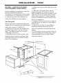
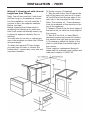
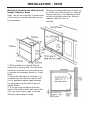
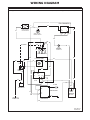
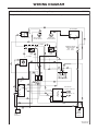
Users Guide & Installation
Handbook
Belling
Built-in Gas - AU
083137410 13.05.2012
CONTENTS & OUR WARRANTY
CONTENTS
•
INTRODUCTION
•
SAFETY
•
IGNITION PROCEDURE
•
USING THE HOB, GRILL AND
OVEN(S)
•
HANDLING BAKING PROBLEMS
If your appliance is covered by the
warranty and guarantee, you will not be
billed for work undertaken should your
appliance be faulty, terms and conditions
do apply, so please read through the
literature carefully.
Please ensure that you have available
your appliances model number and serial
number, there is a space at the back of
this book for recording that information.
•
RECOMMENDATIONS AND GOOD
PRACTICES
Important Notice
•
USING THE CLOCK PROGRAMMER/
MINUTE MINDER
•
CLEANING
•
INSTALLATION INSTRUCTIONS
•
TECHNICAL DATA
•
WIRING DIAGRAMS
•
CUSTOMER CARE
INTRODUCTION
Should you need it . . . .
Inside the paperwork which has come
with this appliance, there is a leaflet and
card explaining the terms of our warranty
and guarantee. Simply fill in the details on
the card and post it off, this will register
your appliance.
Glen Dimplex Australia PTY LTD
1/21 Lionel Road
Mount Waverley
Victoria 3149
Australia
Ph: 1300 556 816
Fx: 1800 058 900
Glen Dimplex New Zealand Pty
38 Harris Road, East Tamaki
Auckland
New Zealand
Ph: 09 274 8265
Fx: 09 274 8472
Please note there may be a cooling fan
fitted to this appliance. It is an integral
part of its safety and functionality. When
the appliance is installed care must be
taken that the cooling fans performance
is not impeded by any objects coming
into contact with it. (Installation pipes,
leads etc) Care must also be taken that
there is sufficient air flow at the rear of
the appliance for the cooling fan to run at
its optimum efficiency, (particularly built
in appliances) see clearance dimensions
in the installation section of the booklet.
During use the appliance must never be
disconnected from the mains supply as
this will seriously affect the safety and
performance of the appliance, particularly
in relation to surface temperatures
becoming hot and gas operated parts
not working efficiently. The cooling fan is
designed to run on after the control knob
has been switched off to keep the front of
the appliance and the controls cool until
the appliance has naturally cooled itself.
SAFETY
BEFORE USING THE PRODUCT
Make sure that you have removed all
packaging and wrapping. Some of the
items inside this appliance may have
additional wrapping.
It is advised that you turn the ovens and/
or grill on for a short while. This will burn
off any residues left from manufacturing.
There may be a smell which accompanies
this process - but this is nothing to worry
about and is harmless.
It is recommended that you wash the
oven shelves, baking tray, grill pan and
grill pan trivet before their first use in hot
soapy water. This will remove the protective oil coating.
Please note:- these safety warnings
cover both gas and electric products.
GENERAL
WARNING! - The
appliance and its
accessible parts become
hot during use. Care
should be taken to
avoid touching heating
elements. Children less
than 8 years of age shall
be kept away unless
continously supervised.
This appliance can
be used by children
aged from 8 years and
above and persons with
reduced physical sensory
or mental capabilities or
lack of experience and
knowledge if they have
been given supervision
or instruction concerning
the use of the appliance
in a safe way and
understand the hazards
involved. Children
shall not play with the
appliance. Cleaning and
user maintenance shall
not be made by children
without supervision.
WARNING! Unattended cooking on
a hob with fat or oil can
be dangerous and may
result in fire.
NEVER try to extinguish
a fire with water, but
switch off the appliance
and then cover the flame
with a lid or damp cloth.
WARNING! - Danger of
fire: Do not store items
on the cooking surfaces.
WARNING! - Servicing
should be carried out
5.1
SAFETY
only by authorised
personnel.
• The appliance must
never be disconnected
from the mains
supply during use,
as this will seriously
affect the safety
and performance,
particularly in
relation to surface
temperatures
becoming hot and gas
operated parts not
working efficiently.
The cooling fan (if
fitted) is designed
to run on after the
control knob has been
switched off.
• Do not spray aerosols
in the vicinity of this
appliance while it is in
operation.
• Do not store or use
flammable liquids or
items in the vicinity of
this appliance.
• Do not modify this
appliance.
CAUTION: The use of
a gas cooking appliance
results in the production
of heat, moisture and
products of combustion
in the room in which it is
installed. Ensure that the
kitchen is well ventilated
especially when the
appliance is in use:
keep natural ventilation
holes open or install a
mechanical ventilation
device (mechanical
extractor hood).
Prolonged intensive use
of the appliance may call
for additional ventilation,
for example opening
of a window, or more
effective ventilation,
for example increasing
the level of mechanical
ventilation where
present.
WARNING! 5.1
SAFETY
Do not operate the
appliance without the
glass panel correctly
fitted.
WARNING! Never put items directly
on the base of the oven
or cover the oven base
with
foil, as this can cause the
base element
to overheat.
WARNING! The top element gets
extremely hot when in
use, so take extra care to
avoid touching it.
WARNING! Do not modify the outer
panels of this appliance
in any way.
WARNING! This appliance must be
earthed.
WARNING! There is a risk of electric
shock, so always make
sure you have turned
off and unplugged your
appliance before starting.
Always allow the product
to cool down before you
change a bulb.
WARNING! - Do not
use harsh abraisive
cleaners or sharp metal
scrapers to clean the
ovendoor glass since
they can scratch the
surface, which may well
result in shattering of the
glass.
GAS WARNING! If you smell gas:
Do not try to light any
appliance.
Do not touch any
electrical switch.
Contact your local gas
supplier immediately.
CAUTION: This
appliance is for cooking
purposes only. It must
5.1
SAFETY
not be used for other
purposes, for example
room heating.
OVEN / GRILL
Do
• Always take care when removing food
from the oven as the area around the
cavity may be hot.
•
•
•
Always use oven gloves when
handling any utensils that have been
in the oven as they will be hot.
Always make sure that the oven
shelves are resting in the correct
position between two runners. Do
not place the oven shelves on top
of the highest runner, as this is not
stable and can lead to spillage or
injury.
Always use the Minute Minder (if
fitted) if you are leaving the oven
unattended - this reduces the risk of
food burning.
Do Not
•
Never place items on the door while
it is open.
•
Never wrap foil around the oven
shelves or allow foil to block the flue.
•
Never drape tea towels near the oven
while it is on; this will cause a fire
hazard.
•
Never pull heavy items, such as
turkeys or large joints of meat, out
from the oven on the shelf, as they
may overbalance and fall.
Never use this appliance to heat anything
other than food items and do not use it
for heating the room.
5.1
USING THE GRILL - ELECTRIC (IF FITTED)
Caution: Accessible parts may be
hot when the grill is used - young
children should be kept away.
A grill pan handle can be purchased as an
optional extra from our spares department
quoting the numbers below.
Handle - 082283705
Handle grip - 082469100
Complete grillpan pack - 012635666
Contact details can be found on the
customer care page.
If cleaning the grill pan when it is hot, use
oven gloves to move it.
Food for grilling should be positioned
centrally on the trivet.
Using the grill
With the grill trivet removed the food is
placed directly on the base of the grill pan
- eg: when cooking whole fish or browning
dishes such as cauliflower cheese.
To switch off, turn the control knob to the
off
position.
Aluminium foil
Using aluminium foil to cover the grill pan,
or putting items wrapped in foil under the
grill creates a fire hazard.
The cooling fan (if fitted)
When the grill is switched on, after a short
delay, the cooling fan comes on to keep
the fascia and control knobs cool during
grilling. The fan may continue to operate for a period after the grill has been
switched off.
During use the fan may cycle on and off,
this is normal.
Important: The grill door must be fully
open when the grill is used.
Open the grill door. Turn the grill control
knob to the grill symbol
position. For
best cooking results, we recommend that
you preheat the grill for about 3 minutes.
Push the grill pan towards the back of the
shelf, to position it under the grill.
The speed of grilling can be controlled by
selecting a higher or lower shelf position.
For toasting, and for grilling foods such as
bacon, sausages or steaks, use a higher
shelf position. For thicker foods such
as chops or chicken joint pieces, use a
middle to low shelf position.
The grill trivet, inside the grill pan, can
be inverted to give a high or low position,
or it may be removed. The HIGH trivet
position is suitable for toasting bread. The
LOW trivet position is suitable for grilling
all types of meat & fish.
7.130
USING THE TOP OVEN - GAS
USING THE TOP OVEN
Preheating
Ignition
Always preheat the top oven for 15 minutes. However, if the main oven is being
used at the same time, then preheating
may not be necessary. The cooking time
may need to be shortened slightly, or the
cooking temperature adjusted, to allow
for heat transfer from the main oven
to the top oven if both ovens are used
together.
Push in and turn the top oven control
knob anticlockwise to the ‘FULL ON’ position. Hold the control knob in, and press
the ignition switch (if fitted) or hold a
lighted match or taper to the burner, until
the burner lights. Hold the control knob
in for 15 seconds. Do not hold the control
knob in for longer that 15 seconds. If
the burner fails to light within this time,
release the control knob and wait one
minute before attempting further ignition.
Turn the control knob to the required
setting.
To switch off, return the control knob to
the off position.
Note; Some appliance’s are automatic
ignition and do not include neither require
an ignition switch.
Using the top oven
The top oven can be used in the same
way as the main oven, to cook the full
range of dishes, but it is a secondary oven
and there are some differences.
Foods cooked in the top oven should be
in relation to the oven size. Larger dishes,
or food which may rise during cooking,
should be cooked in the main oven.
Large items, wide tins and tall items such
as rich fruit cakes should be cooked in the
main oven to obtain optimum results.
Notes:
As part of the cooking process, hot air is
expelled through a vent at the top of the
oven(s). When opening the oven door,
care should be taken to avoid any possible
contact with potentially hot air, since this
may cause discomfort to people with sensitive skin. We recommend that you hold
the underneath of the oven door handle.
If you are not preheating the oven, the
cooking times in the baking guide may
need to be extended, as they are based
on a preheated oven.
The oven must be preheated when
reheating frozen or chilled foods, and
we recommend preheating for yeast
mixtures, batters, soufflés and whisked
sponges.
Put the oven shelves in the position required before preheating the oven.
Zones of heat
The temperature at the centre of the oven
corresponds with the selected gas mark
and is slightly higher towards the top of
the oven and slightly lower towards the
oven base.
These zones of heat can be useful as different dishes requiring different temperatures can be cooked at the same time,
when more than one shelf is used.
The temperature at the oven base is suitable for cooking baked vegetables, baked
fruit, milk pudding etc, and for warming
bread rolls, soup, coffee, or ovenproof
plates and dishes.
If you find that over a period of time,
the oven becomes hotter when used at a
particular gas mark, the thermostat may
need to be replaced.
USING THE TOP OVEN - GAS
OVEN FURNITURE
Slow cooking
Baking tray and roasting tins
Make sure that frozen foods are thoroughly thawed before cooking.
For best cooked results and even browning, the maximum size baking trays and
roasting tins that should be used are as
follows;
Baking tray
350mm x 330mm
Roasting tin
370mm x 320mm
Position baking trays and roasting tins on
the middle of the shelves, and leave one
clear shelf position between shelves, to
allow for circulation of heat.
Oven shelves
Extra shelves may be ordered from your
local supplier.
The oven shelf must be positioned with
the upstand at the rear of the oven and
facing upwards.
The top oven shelf helps to ensure even
baking in the top oven. It has a rear deflector fitted to it, and is not intended for
use in the main oven.
Oven light (if fitted)
Press the light button on the facia panel.
If there is no light button the oven light
will come on when the oven control is
operated.
Do not slow cook joints of meat or poultry
weighing more than 2¼kg / 4½lb.
Always use the top half of the oven for
slow cooking.
For roasting joints of meat or poultry, and
for pot roasts preheat the oven to 195°
and cook for 30 minutes, then adjust the
oven control to the “S” slow setting for
the remainder of the cooking time.
Slow cooking times will be about three
times as long as conventional cooking
times.
USING THE TOP OVEN - GAS
TOP OVEN BAKING GUIDE
Dish
Recommended
temperature
Suggested
Approximate
shelf
cooking time
position
(preheated
oven)
Scones
230
top - middle
10 - 15 mins
Meringues
130
bottom
2 - 3 hours
Small cakes
200
middle
15 - 25 mins
Whisked sponge
200
middle
20 - 30 mins
Swiss roll
215
middle
10 - 12 mins
Victoria sandwich
190
middle
20 - 35 mins
Cakes
(2 x 180mm / 7” per shelf)
Genoese Sponge
(side by side)
200
middle
25 - 30 mins
Rough Puff
230
middle
cooking time
Flaky / Puff
215
middle
depends on
Shortcrust
215
middle
recipe & type
Flan
215
middle
of filling
Shortbread fingers
200
middle - top
Nut brownies
200
middle
Brandy snaps
190
middle - top
Flapjacks
190
middle - top
Ginger nuts
200
middle - top
(2 x 180mm / 7” per shelf)
Pastry
Biscuits
Baking guide hints
The gas mark settings and times given
in the top baking guides are based on
dishes made wit block margarine. If tub
margarine is used, it may be necessary to
reduce the gas mark setting.
If a different gas mark setting to that
shown in our guide is given in a recipe,
the recipe instruction should be followed.
The cooking times given in the baking
guides are based on a preheated oven.
If you do not preheat the oven, cooking
times should be extended.
USING THE TOP OVEN - GAS
Traditional fruit cakes
Roast turkey
It should be remembered that ovens can
vary over time, therefore cooking times
can vary, making it difficult to be precise
when baking fruit cakes.
Roasting turkey involves cooking two
different types of meat - the delicate light
breast meat, which must not be allowed
to dry out, and the darker leg meat,
which takes longer to cook.
It is necessary therefore, to test the cake
before removal from the oven. Use a fine
warmed skewer inserted into the centre of
the cake. If the skewer comes out clean,
then the cake is cooked.
•
Do not attempt to make Christmas
cakes larger than the oven can cope
with, you should allow at least 25mm
(1 inch) space between the oven
walls and the tin.
•
Always follow the temperatures recommended in the recipe.
•
To protect a very rich fruit cake during cooking, tie 2 layers of brown
paper around the tin.
•
We recommend that the cake tin is
not stood on layers of brown paper,
as this can hinder effective circulation
of air.
•
•
Do not use soft tub margarine for
rich fruit cakes, unless specified in
the recipe.
Always use the correct size and
shape of tin for the recipe quantities.
The turkey must be roasted long enough
for the legs to cook, so frequent basting is necessary. The breast meat can be
covered once browned.
•
Always make sure that the turkey is
completely thawed and that the giblets are removed before cooking.
•
Turkey should be roasted at 180° for
20 minutes per lb, plus 20 minutes,
unless packaging advises otherwise.
•
The turkey can be open roasted,
breast side down, for half of the cook
time, and then turned over for the
remainder of the cooking time.
•
If the turkey is stuffed, add 5 minutes
per lb to the cooking time.
•
If roasting turkey covered with foil,
add 5 minutes per 1lb to the cooking
time.
To test if the turkey is cooked, push a
fine skewer into the thickest part of the
thigh. If the juices run clear, the turkey
is cooked. If the juices are still pink, the
turkey will need longer cooking.
Please note:- for all other Roasting guides refer to main oven section and
see table.
USING THE TOP OVEN - GAS
Roasting guide
Notes:
The times given in the roasting guide
are only approximate, because the size
and age of the bird will influence cooking
times as will the shape of a joint and the
proportion of the bone.
•
When cooking stuffed meat or poultry
calculate the cooking time from the
total weight of the meat plus the
stuffing.
•
For joints cooked in foil or covered
roasters, and for lidded casseroles,
add 5 minutes per 450g (1lb) to the
calculated cooking time.
•
Smaller joints weighing less than
1.25kg (2½lb) may require 5 minutes
per 450g (1lb) extra cooking time.
•
Position the oven shelf so that the
meat or poultry is in the centre of the
oven.
•
It is recommended that the appliance
is cleaned after open roasting.
Frozen meat should be thoroughly thawed
before cooking. For large joints it is advisable to thaw overnight.
Frozen poultry should be thoroughly
thawed before cooking. The time required
depends on the size of the bird - eg; a
large turkey may take up to 48 hours to
thaw.
Use of a trivet with a roasting tin will
reduce fat splashing and will help to keep
the oven interior clean. Alternatively, to
help reduce fat splashing, potatoes or
other vegetables can be roasted around
the meat/poultry.
Cook in oven at 180°
Approximate Cooking Time
(preheated oven)
Beef
Lamb
Rare
20 minutes per 450g (1lb), plus 20 minutes
Medium
25 minutes per 450g (1lb), plus 25 minutes
Well done
30 minutes per 450g (1lb), plus 30 minutes
Medium
25 minutes per 450g (1lb), plus 25 minutes
Well Done
30 minutes per 450g (1lb), plus 30 minutes
Pork
35 minutes per 450g (1lb), plus 35 minutes
Poultry
20 minutes per 450g (1lb), plus 20 minutes
USING THE MAIN OVEN - GAS
USING THE MAIN OVEN
Ignition
Push in and turn the main oven control
knob to the ‘FULL ON’ position. Hold the
control knob in, and press the ignition
switch (if fitted) or hold a lighted match
or taper to the burner, until the burner
lights. If after 15 seconds, the burner has
not lit, turn off the oven and leave the
compartment door open. Wait at least one
minute before a further attempt to ignite
the burner.
Do not hold the control knob in for more
than 15 seconds.
Turn the control knob to the required
setting.
Note; Some appliance’s are automatic
ignition and do not include neither require
an ignition switch.
To turn off, return the control knob to the
“off” position.
Preheat the main oven for 15 minutes.
If you are not preheating the oven, the
cooking times in the baking guides may
need to be extended, as they are based
on a preheated oven.
The oven must be preheated when
reheating frozen or chilled foods, and
we recommend preheating for yeast
mixtures, batters, soufflés and whisked
sponges. Put the oven shelves in the position required before preheating the oven.
Zones of heat
The temperature at the centre of the oven
corresponds with the selected gas mark
and is slightly higher towards the top of
the oven and slightly lower towards the
oven base. These zones of heat can be
useful as different dishes requiring different temperatures can be cooked at the
same time, when more than one shelf is
used.
The temperature at the oven base is suitable for cooking baked vegetables, baked
fruit, milk pudding etc, and for warming
bread rolls, soup, coffee, or ovenproof
plates and dishes.
If you find that over a period of time,
the oven becomes hotter when used at a
particular gas mark, the thermostat may
need to be replaced.
Oven light (if fitted)
Press the light button on the facia panel.
If there is no light button the oven light
will come on when the oven control is
operated..
OVEN FURNITURE
Baking tray and roasting tins
For best cooked results and even browning, the maximum size baking trays and
roasting tins that should be used are as
follows;
Baking tray 350mm x 330mm
Roasting tin 370mm x 320mm
Position baking trays and roasting tins on
the middle of the shelves, and leave one
clear shelf position between shelves, to
allow for circulation of heat.
Oven shelves
Extra shelves may be ordered from your
local supplier.
The oven shelf must be positioned with
the up-stand at the rear of the oven and
facing upwards.
SLOW COOKING
Make sure that frozen foods are thoroughly thawed before cooking.
Do not slow cook joints of meat or poultry
weighing more than 2¼kg/4½lb.
Always use the top half of the oven for
slow cooking.
USING THE MAIN OVEN - GAS
For roasting joints of meat or poultry, and
for pot roasts preheat the oven to 215°
and cook for 30 minutes, then adjust the
oven control to the “S” slow setting for
the remainder of the cooking time.
Slow cooking times will be about three
times as long as conventional cooking
times.
MAIN OVEN BAKING GUIDE
Dish
Recommended
temperature
Suggested
shelf position
Scones
230
middle - top
8 - 15 mins
Meringues
125
bottom
2 - 3 hours
200
200
215
185
middle
middle
middle
middle
185
170
170
155 or 170
middle
middle
middle
middle - top
20 - 30 mins
1 - 1¼ hours
1 - 1¼ hours
2½ - 3 hours
140 or 155
bottom
170
middle - bottom
depending on
recipe
2 - 2½ hours
230
215
215
215
middle
middle
middle
middle
-
top
top
top
top
Cooking time
depends on
recipe and type
of filling
200
185
185
185
middle
middle
middle
middle
-
top
top
top
top
25
10
20
10
Cakes
Small cakes
Whisked sponge
Swiss roll
Victoria sandwich
(2 x 180mm/7”)
Genoese sponge
Madeira (180mm/7”)
Gingerbread
Semi rich fruit cake
(205mm/8”)
Christmas cake
(205mm/8”)
Dundee cake (205mm/8”)
Pastry
Rough Puff
Flaky/Puff
Shortcrust
Flan
Biscuits
Nut brownies
Brandy snaps
Flapjacks
Gingernuts
Approximate
cooking time
(preheated
oven)
-
top
top
top
top
15
20
10
20
-
-
25
25
12
30
35
12
25
20
mins
mins
mins
mins
mins
mins
mins
mins
USING THE MAIN OVEN - GAS
Traditional fruit cakes
Roast turkey
It should be remembered that ovens can
vary over time, therefore cooking times
can vary, making it difficult to be precise
when baking fruit cakes.
Roasting turkey involves cooking two
different types of meat - the delicate light
breast meat, which must not be allowed
to dry out, and the darker leg meat,
which takes longer to cook.
It is necessary therefore, to test the cake
before removal from the oven. Use a fine
warmed skewer inserted into the centre of
the cake. If the skewer comes out clean,
then the cake is cooked.
•
Do not attempt to make Christmas
cakes larger than the oven can cope
with, you should allow at least 25mm
(1 inch) space between the oven
walls and the tin.
•
Always follow the temperatures recommended in the recipe.
•
To protect a very rich fruit cake during cooking, tie 2 layers of brown
paper around the tin.
•
We recommend that the cake tin is
not stood on layers of brown paper,
as this can hinder effective circulation
of air.
•
•
Do not use soft tub margarine for
rich fruit cakes, unless specified in
the recipe.
Always use the correct size and
shape of tin for the recipe quantities.
The turkey must be roasted long enough
for the legs to cook, so frequent basting is necessary. The breast meat can be
covered once browned.
•
Always make sure that the turkey is
completely thawed and that the giblets are removed before cooking.
•
Turkey should be roasted at 200° for
20 minutes per lb, plus 20 minutes,
unless packaging advises otherwise.
•
The turkey can be open roasted,
breast side down, for half of the cook
time, and then turned over for the
remainder of the cooking time.
•
If the turkey is stuffed, add 5 minutes
per lb to the cooking time.
•
If roasting turkey covered with foil,
add 5 minutes per 1lb to the cooking
time.
To test if the turkey is cooked, push a
fine skewer into the thickest part of the
thigh. If the juices run clear, the turkey
is cooked. If the juices are still pink, the
turkey will need longer cooking.
USING THE MAIN OVEN - GAS
Roasting guide
Notes:
The times given in the roasting guide
are only approximate, because the size
and age of the bird will influence cooking
times as will the shape of a joint and the
proportion of the bone.
•
When cooking stuffed meat or poultry
calculate the cooking time from the
total weight of the meat plus the
stuffing.
•
For joints cooked in foil or covered
roasters, and for lidded casseroles,
add 5 minutes per 450g (1lb) to the
calculated cooking time.
•
Smaller joints weighing less than
1.25kg (2½lb) may require 5 minutes
per 450g (1lb) extra cooking time.
•
Position the oven shelf so that the
meat or poultry is in the centre of the
oven.
•
It is recommended that the appliance
is cleaned after open roasting.
Frozen meat should be thoroughly thawed
before cooking. For large joints it is advisable to thaw over night.
Frozen poultry should be thoroughly
thawed before cooking. The time required
depends on the size of the bird - eg; a
large turkey may take up to 48 hours to
thaw.
Use of a trivet with a roasting tin will
reduce fat splashing and will help to keep
the oven interior clean. Alternatively, to
help reduce fat splashing, potatoes or
other vegetables can be roasted around
the meat/poultry.
Cook in oven at 200°
Approximate Cooking Time
(preheated oven)
Beef
Rare
Medium
Well done
20 minutes per 450g (1lb), plus 20 minutes
25 minutes per 450g (1lb), plus 25 minutes
30 minutes per 450g (1lb), plus 30 minutes
Lamb
Medium
Well Done
25 minutes per 450g (1lb), plus 25 minutes
30 minutes per 450g (1lb), plus 30 minutes
Pork
35 minutes per 450g (1lb), plus 35 minutes
Poultry
20 minutes per 450g (1lb), plus 20 minutes
CLEANING
General
•
It is important to clean the product
regularly as a build up of fat can affect its performance or damage it and
may invalidate your guarantee.
•
Always switch off your appliance
and allow it to cool down before you
clean any part of it.
•
Do not use undiluted bleaches,
products containing chlorides, wire
wool or abrasive cleaners on aluminium, stainless steel, or plastic/
painted parts as they can damage
the appliance. Nylon pads can also be
unsuitable.
•
Take extra care when cleaning over
symbols on fascia panels. Excessive
cleaning can lead to the symbols
fading.
•
If your product is fitted with stainless
steel cladded stips. You may notice
a small white residue on the outer
edges, this can be removed with a
non abrasive wipe.
•
Some foods are corrosive eg; vinegar,
fruit juices and especially salt - they
can mark or damage the metal if they
are left on the surface.
•
Baby oil can be used to restore stainless steel finishes - but only use a
few drops. Don’t use cooking oils
as they can contain salts, which will
damage the metal.
• Do not use steam cleaners.
Enamel surfaces & parts
•
Clean with warm, soapy water and a
clean cloth.
•
If larger splashes of fat do not readily
disappear, you can use a mild cream
cleaner to remove them. More stubborn marks can be removed using a
soap filled pad.
•
Rinse well and dry with a soft clean
towel or cloth.
•
Do not use steam cleaners.
Painted & Plastic parts
Glass parts
•
Only use a clean cloth wrung out in
hot soapy water.
•
Do not use abrasive cleaners, wire or
nylon cleaning pads on these parts.
WARNING:- Do not use harsh
abrasive cleaners or sharp
metal scrapers to clean the
oven door glass since they can
scratch the surface, which may
result in shattering of the glass.
Stainless steel & Aluminium surfaces
•
Only use a clean cloth wrung out in
hot soapy water, and dry with a soft
cloth.
•
Stubborn marks can be removed using a stainless steel cleaner. Supplies
can be purchased from the Customer
Care Centre.
•
Sharp objects can mark the surface
of stainless steel, but will become
less noticeable with time.
•
Wipe any spillage immediately, taking
care to avoid burning your hands
•
Only use a clean cloth wrung out in
hot soapy water, or a specialist glass
cleaner.
Rinse away any excess cleaner and dry
with a soft cloth.
Chrome plated parts
•
Use a moist soap filled pad, or place
in a dishwasher
12.000
CLEANING
REMOVING OVEN PARTS FOR
CLEANING
Inner Door Glass (glass doors only)
•
The inner door glass panel can be
removed for cleaning but it must be
replaced the right way up. If there is
any writing on the glass, you must be
able to read it clearly when the cavity
doors are open.
•
Always make sure that the glass is
pushed fully into the Stop position.
•
To remove the glass panel, open the
door wide, hold the top and bottom
edges and slide out.
that it is replaced immediately.
Shelf Runners
•
Shelf runners can be removed to
enable you to clean them thoroughly.
Make sure they are cool to touch and
then grasp the runners and slide out
of their hanging holes.
Pull out to clean
• Warning: Do not operate
the appliance without the
glass panel correctly fitted.
•
For your safety, glass door panels are
made of toughened glass. This ensures that, in the unlikely event that
a panel breaks, it does so into small
fragments to minimise the risk of injury. Please take care when handling,
using or cleaning all glass panels, as
any damage to the surfaces or edges
may result in the glass breaking
without warning or apparent cause at
a later date. Should any glass panel
be damaged, we strongly recommend
12.100
INSTALLATION
Before you start: Please read the instructions. Planning your installation will save
you time and effort.
Prior to installation, ensure that the local
distribution conditions (nature of the gas
and gas pressure) and the adjustment of
the appliance are compatible. The adjustment conditions are stated on the data
badge.
This appliance is not connected to a combustion evacuation device. It shall be installed and connected in accordance with
current installation regulation. Particular
attention shall be given to the relevant
requirements regarding ventilation.
The information below is crucial to installing this appliance correctly and safely.
Gas Safety (Installation & Use)
Regulations
This appliance must by an authorised
person in accordance with the Australian Gas Installation Standard AS5601
the manufacturers installation instructions, local gas fitting regulations, and
any other relevant statutory regulations.
Particular attention should be given
to relevant requirements regarding
ventilation.
Failure to install appliances correctly is dangerous and could lead to
prosecution.
Ventilation Requirements
Ventilation must be as specified by AS
5601 Installation code. The room containing the appliance should have an air
supply.
An appliance should be installed in a
location for complete combustion of gas,
proper flueing and to maintain ambient
temperature of the immediate surrounding at safe limits, under normal conditions.
Failure to install appliances correctly is dangerous and could lead to
prosecution.
WARNING! - This appliance is unsuitable for use in a marine environment.
If the appliance is placed on a base,
measures have to be taken to prevent it
slipping from the base.
Caution: The use of gas cooking appliance results in the production of heat,
moisure and products of combustion in
the room in which it was installed. Ensure
that the kitchen is well ventilated especially when the appliance is in use: keep
natural ventilation holes open or install a
mechanical ventilation device (mechanical
extractor hood).
INSTALLATION 60CM
STEP 1 : PREPARE INSTALLATION
Do not lift the appliance by the door
handle.
Whilst every care is taken to eliminate burrs and raw edges from this
product,please take care when handling
- we recommend the use of protective
gloves during installation.
Please note that the weight of this appliance is approximately 31kg (unpacked).
Take care when lifting it into the housing
unit - always use an appropriate method
of lifting.
Remove the fixing screws from the
polythene bag on the top of the appliance, but leave the appliance in the base
tray packaging until you are ready to
install it.
If this appliance is to be installed near to
a corner where the adjacent cabinets run
at right angles forward of the appliance,
there must be a gap of at least 90 mm
between the appliance and the cabinets,
to prevent overheating of the cabinets.
Housing dimensions
The appliance is designed to fit into a
standard 600mm wide housing unit with
minimum internal dimensions as shown.
590mm is to the underside of the worktop
when the appliance is built under, or to
the underside of the panel above, when
the appliance is installed into a tall housing unit.
INSTALLATION - 60CM
i) When installed in a typical 600mm
deep built in housing unit, the false back
should be removed from the housing unit
to provide the necessary depth for installation.
ii) When the false back is removed, it is
normally the case that the support shelf
for the appliance leaves a gap between
the back edge and the wall of approximately 80mm.
iii) If no gap occurs between the back
edge of the shelf and the wall behind the
unit, we recommend that a gap of at least
30mm is made by shortening the shelf.
iv) When installing the appliance below a
worktop, there must be a minimum ventilation area of 60cm2 below the appliance,
in either area (1) or (2), as indicated below. There must be a 5mm gap between
the front top edge of the oven and the
underside of the worktop.
Important: Do not modify the outer panels of this appliance in any way.
Ensure that you route all mains electrical cables and flexible tubing well clear
of any adjacent heat source, such as an
oven, grill or hob.
Ensure that all pipe work is of the correct
rating for both size and temperature.
Installing the appliance under a
worktop
Where the appliance is installed under a
worktop, with a hob installed above it,
the installation instructions for the hob
must be read in conjunction with these
instructions.
INSTALLATION - 70CM
Before you start
Please read the instructions carefully planning your installation will save you
time and effort.
Look at the different ways the appliance
can be installed - as shown on the following pages - and plan the installation
to suit your situation.
Leave the appliance in the base tray
packaging until you are ready to install
it. When you remove the appliance from
the base tray packaging, take care not to
damage it.
Whilst every care is taken to eliminate
burrs and raw edges from this product,
please take care when handling - we
recommend the use of protective gloves
during installation.
Please note that the weight of this appliance is approximately 47kg (unpacked).
Take care when lifting it into the housing
unit - always use an appropriate method
of lifting.
at right angles forward of the appliance,
there must be a gap of at least 90mm
between the appliance and the cabinets,
to prevent overheating of the cabinets.
Important: Do not modify the outer
panels of this appliance in any way.
Fixing screws - The fixing screws are in a
polythene bag in the oven pack. Depending on the method of installation, some of
the screws may not be needed.
Step 1: Prepare for installation
There are 3 methods of installing the appliance:
•
Method 1: Into a space between two
base units, ie; without a housing
unit.
•
Method 2: Into a housing unit,
with an internal height of less than
710mm, which can be modified to
obtain the required dimensions.
•
Method 3: Into a housing unit, with
an internal height of 710mm or
more. If you have a non standard
size of cabinet which leaves a gap
above or below the appliance, you
may be able to buy a trim kit (to fill
in the gap) from the supplier of your
cabinets.
This appliance must be installed only
at low level - ie; under a worktop. The
controls have been designed for viewing
at a low level, and it should therefore not
be installed at high level.
Please note that all dimensions and sizes
given are nominal, some variation is to
be expected.
If this appliance is to be installed near to
a corner where the adjacent cabinets run
Quantity
Colour
Description
For Fixing
6
Silver
No 8 x 12mm long
Self tapping screw
Runners to appliance
12
Black
No 8 x 12mm long
Chipboard screw
Runners and sidetrims to
cabinet or housing
6
Black
No 8 x 25mm long
Chipboard screw
Appliance to cabinet
2
Silver
No 8 x 12mm long
Self tapping screw
Appliance to sidetrims
INSTALLATION - 70CM
METHOD 1: WITHOUT HOUSING
UNIT(BETWEEN 2 BASE UNITS)
Before installing the appliance, check the
internal dimensions as shown.
The space for the appliance must be clear
of obstruction. You may have to cut into
or remove any rear cross members to
obtain the 550mm minimum depth.
The Fixing Kit
Should you need a replacement fixing kit
please call the customer care helpline and
order part number: 01 28287 00.
In the fixing kit you will find 2 side trims
(687mm long) and 4 runners (420mm
long). The fixing screws are in a polythene bag in the oven.
1. Take the 6 No 8 x 12mm (silver) self
tapping screws from the polythene bag,
and use them to fit one runner to each
side of the appliance.
2. Make sure they are the right way up as
shown.
3. Take one of the side trims, hold it
against the side of the base unit, and
mark off 687mm from the top edge of the
base unit, to the top edge of the runner.
Note: This ensures a 5 - 8mm clearance
from the underside of the worktop to the
top of the appliance.
4. Measure 50mm from the front edge of
the base units, to mark the front edge of
the runners.
5. Take 6 of the No 8 x 12mm (Black)
chipboard screws and screw the runners into opposition the right way up as
shown.
6. Fit the side trims to be flush to the top
and front edges of the base units, using
the remaining 6 No 8 x 12mm (Black)
chipboard screws.
INSTALLATION - 70CM
Method 2: Housing unit with internal
height less than 710mm.
Note: You will not need the 2 side trims
(687mm long) or the appliance runners
for this installation. You will need the 2
runners to fix to the adjacent cabinets.
Before you start;
Before removing the bottom shelf or
modifying the housing unit, make sure
that it will remain structurally sound, eg;
by fixing to adjacent cabinets, floor or
worktop.
You may have to cut into or remove any
rear cross members to obtain the 550mm
minimum depth.
To obtain the required 710mm height,
you may have to lower or remove the
bottom shelf - remove any cross rails and
reposition brackets.
To fix the runners (if required)
1. Take the side trims, hold it against the
side of the base unit, and use it to mark
off the 687mm from the top edge of the
side unit, to the top edge for the runner.
Note: This ensures a 5 - 8mm clearance
from the underside of the worktop to the
top of the appliance.
2. Measure 50mm from the front edges of
the base units, to mark the front edge for
the runners.
3. Take 6 of the No 8 x 12mm (Black)
chipboard screws and screw the runners
into position the right way up as shown.
4. If necessary, adjust the height of the
plinth to just below the bottom edge of
the runners.
If you require a replacement fixing kit
please call the customer care helpline and
order part number 01 28287 00.
INSTALLATION - 70CM
Method 3: Housing unit with internal
height 710mm or more
Note: You will not need the 4 runners and
2 trims that are packed with the oven for
this installation.
1. When installed in a typical 600mm
deep built in housing unit, the false back
should be removed from the housing unit
to provide the necessary depth for installation.
2. When the false back is removed, it is
normally the case that the support shelf
for the appliance leaves a gap between
the back edge and the wall of approximately 80mm.
3. If no gap occurs between the back
edge of the shelf and the wall behind the
unit, you must create a gap of at least
30mm by shortening the shelf.
Remove any fixings that may prevent entry of the oven into housing, or obstruct
the gas inlet pipe. The cabinetry should
be kept structurally sound by fixing to
adjacent cabinets, floor or
worktop.
INSTALLATION - 90CM
STEP 1 : PREPARE INSTALLATION
Do not lift the appliance by the door
handle.
Remove the fixing screws from the
polythene bag on the top of the appliance, but leave the appliance in the base
tray packaging until you are ready to
install it.
Whilst every care is taken to eliminate
burrs and raw edges from this appliance,
please take care when handling - we
recommend the use of protective gloves
during installation.
Please note that the weight of this appliance is approximately 48kg (unpacked).
Take care when lifting it into the housing
unit - always use an appropriate method
of lifting.
Note: When removing the appliance from
the base tray packaging care should be
taken to ensure the appliance is not damaged.
Siting the appliance
If this appliance is to be installed near to
a corner where the adjacent cabinets run
at right angles forward of the appliance,
there must be a gap of at least 90mm
between the appliance and the cabinets,
to prevent overheating of the cabinets.
When installed in a typical 600mm deep
built in housing unit, the false back
should be removed from the housing unit,
to provide the necessary depth for installation.
When the false back is removed, it is normally the case that the support shelf for
the appliance leaves a gap between the
back edge of the support shelf and the
rear wall of approximately 80mm.
If no gap occurs between the back edge
of the shelf and the wall behind the unit,
you must create a gap of at least 30mm
by shortening the shelf and any other
shelf below the appliance.
Cut 12mm from the top of any plinth that
may be fitted (see diagram).
Important: Do not modify the outer panels of this appliance in any way.
INSTALLATION - 90CM
Dimensions
The appliance is designed to fit into a
standard 600mm wide housing unit, with
minimum internal dimensions as shown.
Note: All sizes are nominal, some variation
is to be expected.
INSTALLATION
STEP 2 : CONNECT TO GAS SUPPLY
Means of isolation shall be provided at the
shut off point by either an approved quick
connect device or a Type 1 manual shut
off valve. The outlet of the quick connect
device shall be at, or below, the horizontal
position.
housing unit (e.g.; drawer) and does not
pass through any space susceptible of
becoming congested. Make sure that the
flexible connector does not block the cooling fan inlet.
4. Natural gas installations must conform to local codes or, in the absence of
local codes, with AS:5601 as well as the
requirements of any local council, gas,
electricity authority or other statutory
regulation.
5. Rigid connections must be accessible
to disconnect for servicing. Cut a 150mm
square hole in the right hand rear corner
of the support shelf for the supply pipe.
6. Make sure all connections are gas
sound.
Connection to the gas supply should be
made using the Aquaknect AS/NZS 1869
class B hose assembly with an internal
diameter of not less than 10mm and regulator (regulator for use with natural gas)
NOTE: Maximum length of hose 900mm.
The temperature rise of the areas at the
rear of the cooker that are likely to come
into contact with the flexible hose do not
exceed 70˙C.
1. The inlet to the appliance is ISO 7
- Rp ½” internal thread situated towards
the top right hand rear corner.
2. Fit the bayonet connection to the wall
in shaded area as shown.
The shaded area shown is applicable to
installations in minimum depth cabinets.
If more room is available, the bayonet
fixing area can be extended, provided that
the flexible tube does not obscure the fan
intake.
3. Use a 900mm - 1125mm length of
flexible connector. The flexible connector
shall be fitted such that it cannot come
into contact with a moveable part of the
Pressure test point
The pressure test point is fitted on the
outlet of the regulator or on an adapter
which should be fitted onto the outlet of
the regulator.
INSTALLATION
STEP 3: Connect to the electricity
supply - Gas (mains ignition models
only)
Warning: This appliance must be earthed.
The flexible mains lead is supplied connected to a mains plug which complies
with AS/NZS 3112.
Replace only with a plug of the same type
and rating.
WIRING SIDE OF THE PLUG
As the colours of the wires in the mains
lead for the appliance may not correspond
with the coloured markings identifying the
terminals in your plug, proceed as follows:
1. The wire which is coloured green and
yellow must be connected to the terminal
marked E
(Earth) or coloured
Green.
2. The wire which is coloured blue must
be connected to the terminal marked N
(Neutral), or coloured Black.
3. The wire which is coloured brown must
be connected to the terminal marked L
(Live), or coloured Red.
The plug and socket must be accessible
after installation. Should the mains lead of
the appliance ever require replacing, this
must be carried out by a qualified electrician who will replace it with a lead of the
same size and temperature rating.
Important: - ensure that you route all
mains and electrical cables and flexible
tubing well clear of any adjacent heat
source.
Under no circumstances should the mains
electric cable be allowed to come into
contact with the vertical oven flue tubes
on the rear of the appliance.
INSTALLATION
STEP 4: SECURE APPLIANCE INTO
HOUSING UNIT
Note : The unit housing the appliance
must be appropriately fixed. Ensure that
the appliance is centrally located. Take
care not to damage the appliance or
cabinetry.
70cm only
Method 1 : Care must be taken to ensure
the appliance runners are sufficiently
engaged over the top of the runners on
the base units.
Method 2 : Insert appliance into the cabinet - ensure that it is engaged over the
top of the side runners.
Method 3 : Insert appliance into cabinet
Note: For installation Method 1, you will
need to drill through the fixing holes into
the side trims with a 3.2mm diameter
drill.
There are 4/6 black no 8 x 25mm long
chipboard screws for securing appliance
to cabinet. Insert appliance into cabinet
and secure.
60cm ovens
- Open the oven door and screw the 4
fixing screws through the holes in the front frame.
70/90cm ovens
- Open the grill / top oven door, and
screw 2 fixing screws through the top corner holes in the front frame.
- With the grill / top oven door still open,
screw 2 fixing screws through the holes
located under the grill compartment.
Close the grill / top oven door.
- Open the main oven door and screw 2
fixing screws through the bottom corner
holes in the front frame.
60/70/90 fixing positions
INSTALLATION
Anti-stain trim (if fitted)
The anti-stain trim is factory fitted to the
edges of the appliance front frame.
This trim provides the cabinetry with
extra protection from any escape of heat.
- When Installing the product, ensure
the anti-stain trim is correctly located
on the edges of the front frame, before
positioning and securing the appliance to
the cabinet.
- When securing the appliance, the fixing
screws provided are driven through the
anti-stain trim into the cabinet.
Note : When supplied the anti-stain trim
may be loose and is only supported by
plastic rivets. The anti-stain trim will be
secured when the fixing screws are fully
home into the cabinet. The plastic rivets
should not be removed.
Edging strip (if fitted)
The edging strip is factory fitted to the
edges of the appliance front frame. This
strip provides the cabinetry with extra
protection from any escape of heat.
When installing the product, ensure that
the edging strip is correctly located on
the outer edges of the front frame, before
positioning and securing the appliance to
the cabinet.
When securing the appliance, the fixing
screws provided are driven through the
edging strips into the cabinet - the seal
will straighten up and sit flush to the cabinet when the screws are fully home.
INSTALLATION
Commissioning
Before leaving the installation
Burner aeration
Show the customer how to ignite the oven
and operate the grill and give them this
handbook. Thank you.
All burners have fixed aeration and no
adjustment is possible.
Pressure setting
See technical data.
Electrical systems check
In the event of an electrical fault the
preliminary electrical system check (earth
continuity, short circuit, polarity and resistance to earth) must be carried out.
Ignition check
Oven ignition:
Push in and turn the main oven control
knob anti clockwise to the ‘FULL ON’
position. The ignition system will spark
automatically. Push in the control knob to
ignite the gas. The sparking will stop. If
after 15 seconds, the burner has not lit,
turn off the oven and leave the compartment door open. Wait at least one minute
before a further attempt to ignite the
burner.
Do not hold the control knob in for more
than 15 seconds.
Turn the control knob clockwise to the
required setting.
To turn off, return the control knob to the
“off” position.
Grill ignition:
•
The door must be open for grilling.
•
Push in and turn the control knob clockwise to the grill symbol. Before
leaving the installation
Show the customer how to ignite the oven
and operate the grill and give them this
handbook. Thank you.
TECHNICAL DATA
Data badge
Lower part of front frame and rear of
appliance
Type of gas
This cooker must only be used on Natural
Gas or LPG only.
Gas category Natural Gas/ULPG
Pressure setting
Natural Gas @ 1.0 kPa - ULPG @2.75kPa
Appliance class
Class 3, built-in oven and grill
Countries of destination
AU & NZ
Electrical supply
240V ~ 50Hz
Max load @ 240V
60G - 1885W / 70G & 90G - 1920W
Warning: This cooker must be earthed.
60cm
Gas
Burner
Nominal Rate on
Injector size
Nat gas
Oven
9.0 MJ/h
144
Grill
Electric - 1850W
NA
Total heat input
9.0 MJ/h
Gas
Burner
Nominal Rate on
Injector size
LPG
Oven
8.46 MJ/h
0.82
Grill
Electric - 1850W
NA
Total heat input
8.46 MJ/h
60cm
70/90cm - Double Oven
Gas
Burner
Nat gas
Nominal Rate on
Injector size
Main Oven
9.0 MJ/h
144
Top Oven
6.3 MJ/h
180 Amal
Grill
Electric - 1850W
Total heat input
15.3 MJ/h
70/90cm - Double Oven
Gas
Burner
Nominal Rate on
Injector size
LPG
Main Oven
8.46 MJ/h
0.82
Top Oven
6.50 MJ/h
0.72
Grill
Electric - 1850W
Total heat input
14.96 MJ/h
WIRING DIAGRAM
BELLING BI 60G - AU
ISSUE B
Wiring colour code: Bk -Black, Bn -Brown, Bu -Blue, Gn -Green or Green/Yellow, Or -Orange, R -Red, W -White, Y -Yellow.
Y
NC
C
NO
Y
PROGRAMMER
Bn
W
N
Bn
1
1a
GRILL T/OVEN
MICROSWITCH
Or
Bn
GRILL T/OVEN
ROTARY SWITCH
Bu
L
Y
Bn
Bk
Gn
Bu
Gn
IF FITTED
W
L70c
THERMAL
CUTOUT
Or
GRILL ELEMENT
W
Bn
COOLING FAN
Bu
W
Bu
Bu
Gn
Gn
Bn
Bk
Or
OVEN
LAMP Bu
W
I/P 2
I/P 1
Gn
I/P 3
O/P
W
Bk
W
FAN TIMER
PCB
Bn
L N
Bu
Bk
OVEN
OVEN
SOLENOID
N
ELECTRODES
L1
W
W
Bu
W
Gn
Gn
N
L
MAINS
INLET
TERMINAL
BLOCK
IGNITION
GENERATOR
PUSH ON
EARTH TAB
Bk
08 27483 01
30/08/2012
WIRING DIAGRAM
BELLING BI 70/90G - AU
Wiring Diagram
ISSUE D
Wiring Colour Code : Bk -Black, Bn -Brown, Bu -Blue, Gn - Green/Yellow, Or -Orange, R -Red, W -White, Y -Yellow.
Bn
PROGRAMMER
Bn
NO
1a
1
C
R
Or
N
R
NC
w
GRILL T/OVEN
MICROSWITCH
L
MAIN OVEN
ROTARY SWITCH
GRILL T/OVEN
ROTARY SWITCH
Bn
Bn
w
IF FITTED
w
R
MAIN
OVEN
LAMP
R
TOP
OVEN
LAMP
Gn
Bk
BK
w
IF FITTED
Bu
w
Or
Or
Bu
Bk
COOLING FAN
Bk
Gn
1 2 3 4
Bk
T/OVEN (04828 05)
Bk
Gn
Bn
MAIN
OVEN
SOLENOID
N
Bk
M/OVEN (04828 05)
IGNITION
GENERATOR
w
Bk
Bu
ELECTRODES
R
L N
w
w
R
w
GRILL ELEMENT
Gn
L1 L2
O/P
Bu
I/P 2 I/P 3
I/P 1
w
Bn
w
FAN TIMER
PCB
Gn
Bk
Or
w
R
w
Gn
Or
w
Gn
w
L
Bk
w
THERMAL SWITCH
SPECIFICATION
70G - L70c
90G - L100c
Bu
Gn
Bn
Gn
Or
N
MAINS
INLET
TERMINAL
BLOCK
08 27513 02
30/08/2012
CUSTOMER CARE
FAQs
What parts of the appliance can be
washed in a dishwasher?
•
Any enamelled parts such as the grill
pan can be cleaned in a dishwasher,
as can oven shelves and shelf guides.
duce condensation when the oven is
cooling down with food inside.
Should the cooling fan continue to
run once the appliance has been
switched off?
•
What parts must NOT be cleaned in a
dishwasher?
•
Parts such as burner skirts and caps,
control knobs and any cast iron items
must not be cleaned in a dishwasher,
they should be cleaned with hot
soapy water and a nylon brush once
they are cool enough.
Can all gas appliances be converted
from Natural Gas to LP Gas?
•
There’s been a power failure and the
product won’t work.
•
Switch off the electricity supply.
•
When the power returns switch the
electricity supply back on and re-set
any programmer/clock to the correct
time of day.
No. You can only use one or the
other.
Why is there condensation on the
doors?
•
Condensation is caused by hot, moist
air meeting a cooler surface (i.e. the
oven door). You cannot always prevent it, but you can minimise it when
it happens by doing the following:
•
Preheat the oven at a high temperature before putting food in the oven,
and cover the food you are cooking
wherever possible.
•
Whenever you can, cook wet foods at higher temperatures.
•
Don’t leave food in the oven to cool
down.
•
Automatic cooking will normally pro-
Not all gas appliances can be converted. If Category II is stated on
the databadge, then the appliance
may be converted and a conversion
kit must be obtained if not already
provided. If in doubt, please contact
Customer Care for further advice - do
not attempt to convert an appliance if
it is not compatible.
Why won’t the ignition work?
•
My oven is a single combined oven
and grill - can I use both functions
together?
•
Yes. This is to make sure that you
can always touch the control knobs to
make temperature adjustments, and
turn your appliance off.
Check there is a spark when the ignition button is depressed. If there is
no spark, check the electricity supply
is switched on at the socket. Check
that the gas supply is switched on.
Call Customer Care for a Service
Engineer’s visit if:
•
You find that the oven becomes hotter at a particular temperature - the
thermostat may need replacing.
•
The cooling fan fails to work.
CUSTOMER CARE
CHANGING LIGHT BULBS
(where fitted)
Warning: There is a risk of electric shock, so always make
sure you have turned off and unplugged your appliance before
starting. Always allow the product to cool down before you
change a bulb.
Not all appliances have the same number and type of bulbs. Before replacing your
bulb, open the oven door and see which type you have. Then use the table to help you
change your bulb correctly.
Bulbs can be purchased from hardwarestores (always take the old bulb with you).
Please remember that bulbs are not covered by your warranty.
No of Lamps
Instructions
1
Remove the oven shelves.
Remove the loose oven back by unscrewing the 4 securing screws
(one at each corner) and remove (Where fitted).
Unscrew the lens cover by turning anticlockwise.
Remove the bulb and replace.
Replace the lens cover and oven back.
15.040
Please keep this handbook for future reference, or for anyone else
who may use the appliance.
Please keep this handbook for future reference, or for anyone else
who may use the appliance.
CONTACT US
Calling for a service
If you should experience any problems with your cooker please contact your retailer or
place of purchase.
Important note:
Service work is to be conducted by authorised persons only. It is advisable to have
your cooker checked regularly and maintained in good condition. An annual maintenance is recommended.
Always check the instruction book before calling a service agent to make sure you have
not missed anything.
Glen Dimplex Australia Pty Ltd Customer Care:
Tel: Australia 1-300-556-816
New Zealand 09-274-8265
Before you contact a service agent, make sure that you have the following information
to hand:
Model Number
Serial Number
Date of Purchase
Postcode
Glen Dimplex Australia PTY Ltd, Unit 1/21, Lionel Road,
Mount Waverley, Victoria 3149, Australia.
e-mail: [email protected]
web: www.glendimplex.com.au