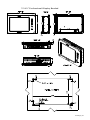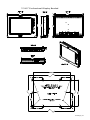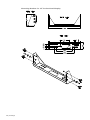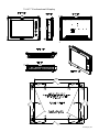
1
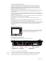
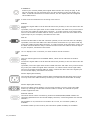
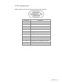
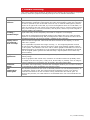
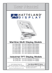
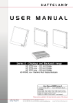
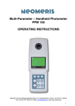
Manual
Simrad Professional Displays
English
www.simrad-yachting.com
A brand by Navico - Leader in Marine Electronics
MANUAL
Professional displays
English
Document no:
20222378
Revision :
C
Date:
September 2008
The original language for this document is English. In the event of any discrepancy
between translated versions and the English version of this document, the English
document will be the official version
To the best of our knowledge, the content in this publication was correct at the time of
printing.
As we are continuously improving our products we retain the right to make changes to
the product and the documentation at any time. Updated manuals are available from
our website www.simrad-yachting.com, and are free to download.
© Copyright 2008 by Navico Holding AS.
Copyright
All rights reserved. No part of this document may be reproduced or otherwise copied
without prior written permission of Navico Holding AS.
© 2007 by Navico Holding AS
About this manual
This manual holds information for installing and using the Simrad professional displays.
Important text that requires special attention from the reader is emphasized as follows:
Used to draw the reader’s attention to a comment or some important information
Used when it is necessary to warn personnel that a risk of damage to the
equipment or injury/death exists if care is not exercised.
Sections
The document includes the following sections:
1
General information
Information about display types and how they are identified
2
Operation
Description of keys and OSD menu
3
Installation
Mechanical installation, cable connection and plug description
4
Trouble shooting
List of probable faults and recommended action to fix the problem
5
Spare parts
List of standard and optional spare parts for the displays
6
Specifications
Mechanical and technical specifications for the various display models
7
Drawings
Mechanical drawings and panel cut-outs for all display models
2 | Introduction
Content
1 General information ............................................................................. 5
1.1 Display types ................................................................................... 5
1.2 Display identification......................................................................... 5
2 Operation............................................................................................. 7
2.1 User controls ................................................................................... 7
2.2 Turning the display on/off.................................................................. 8
2.3 Display illumination .......................................................................... 8
2.4 Assignable hotkeys ........................................................................... 8
2.5 ECDIS Calibration LED ...................................................................... 8
2.6 OSD menu ...................................................................................... 9
2.7 OSD menu overview ....................................................................... 11
3 Installation ........................................................................................ 21
3.1 Installation recommendations .......................................................... 21
3.2 Physical connections ....................................................................... 23
3.3 Pin assignments ............................................................................. 25
4 Trouble shooting................................................................................ 27
5 Spare parts ........................................................................................ 29
6 Specifications .................................................................................... 31
6.1 10” Professional Display Bonded ....................................................... 31
6.2 12”Professional Display Bonded ........................................................ 33
6.3 15” Professional Display Bonded ....................................................... 35
6.4 17” Professional Display .................................................................. 37
6.5 19” Professional Display Bonded ....................................................... 39
6.6 23” Professional Display .................................................................. 41
7 Drawings ........................................................................................... 43
7.1 10” Professional Display Bonded ....................................................... 43
7.2 12” Professional Display Bonded ....................................................... 45
7.3 15” Professional Display Bonded ....................................................... 47
7.4 17” Professional Display .................................................................. 49
7.5 19” Professional Display Bonded/ECDIS ............................................. 51
7.6 23” Professional Display AC/DC/ECDIS .............................................. 53
Introduction |3
Blank page
4 | Introduction
1 General information
1.1 Display types
This manual describes the 10” to 23” Simrad professional displays.
The following type designations are used:
Size
10”
12”
15”
17”
19”
23”
•
Product name
Supply voltage
JH type
10” Pro display, AC, bonded
115/230V AC
JH 10T06 SYE-D1
10” Pro display, DC, bonded
24V DC
JH 10T06 SYE-D2
12” Pro display, AC, bonded
115/230V AC
JH 12T04 SYE-D1
12” Pro display, DC, bonded
24V DC
JH 12T04 SYE-D2
15” Pro display, AC, bonded
115/230V AC
JH 15T06 SYE-D1
15” Pro display, DC, bonded
24V DC
JH 15T06 SYE-D2
17” Pro display, AC
115/230V AC
JH 17T02 SYE-A1
17” Pro display, DC
24V DC
JH 17T02 SYE-A2
19” Pro display, AC, bonded
115/230V AC
JH 19T03 SYE-D1
19” Pro display, DC, bonded
24V DC
JH 19T03 SIM-D2 *
19” Pro display, DC, bonded
24V DC
JH 19T03 SYE-D2 *
19” Pro display, DC, ECDIS
24V DC
JH 19T02 SYE-E2
23” Pro display, AC
115/230V AC
JH 23T02 SYE-A1
23” Pro display, DC
24V DC
JH 23T02 SYE-A2
23” Pro display, AC, bonded
115/230V AC
JH 23T02 SYE-D1
23” Pro display, DC, bonded
115/230V AC
JH 23T02 SYE-D2
23” Pro display, DC, ECDIS
24V DC
JH 23T02 SYE-E2
Identical to 19” IMO Radar display. When delivered for the IMO Radar system the
monitor will be labeled CF19 on the front.
1.2 Display identification
The display identification is found as plain text and with a code on the product label
located on the back side of the monitor.
Product name
Product ID:
26057109 BA 023
part no
revision code
serial number
The display could also be identified by the sticker located on the front cover. Refer
Adding product labels, page 23.
General information |5
Blank page
6 | General information
2 Operation
2.1 User controls
MENU
Used to bring up the On Screen Display (OSD menu) and also for navigating to the next
function.
Used for navigating up through available options on the menu/sub menus.
Used for decreasing/adjusting values in the menu/sub menus.
Used for increasing/adjusting values in the menu/sub menus.
Used for navigating down through available options on the menu/sub menus.
ECDIS Calibration Led. Only available on ECDIS versions.
Used to adjust overall brightness of the picture including LED and lights.
Power LED
PWR
On/Off button.
Operation |7
2.2 Turning the display on/off
PWR
This display features an Instant-ON/Delay-OFF switch, which ensures that the display is
not turned off by user accident.
Power ON:
To turn the display on, press down the power switch. The power light
indicator will turn green.
If no RGB signal sync is present, “NO SYNC” message will appear in the
display.
Power OFF:
seconds.
To turn the display off, press and hold the power switch down for 3
2.3 Display illumination
The image and LED brightness is adjusted by the rotary knob.
The display features a 100% dimmable image, which means it is capable of displaying a
completely black image when the dimmer knob is turned fully to the left. All visible LED
and lights will also dim.
2.4 Assignable hotkeys
The user can assign various display functions as hotkeys to the increase/decrease keys
This will enable the user to quickly adjust the brightness, image size, contrast or other
functions to control the image. To assign these hotkeys, enter the “UTILITIES
MENU/DIRECT ACCESS” menu and change them to the desired hotkey function.
Default hotkeys are set to increase/decrease contrast.
2.5 ECDIS Calibration LED
The calibrated led indicator is only active for displays which are calibrated for ECDIS.
Each ECDIS factory prepared display has its individual backlight brightness setpoint,
where it is in accordance with the ECDIS standard. To adjust the backlight brightness to
this setpoint, turn the brightness knob until the led indicator is on (emits green light).
For verification, a small sticker on the back cover are placed over the setpoint adjust hole.
Do NOT remove the sticker and attempt adjust, doing so will make the ECDIS calibration
invalid!
8 | Operation
2.6 OSD menu
The On Screen Display (OSD menu) controls are as default located on the right side of the
display. In the OSD menu you can select other display locations for the menu. The
selection will be stored in the display.
The On Screen Display (OSD menu) contains several functions that will let the user to
adjust or setup the display to their preferred setting. The functions are shown as easy
understandable icons.
Some of the menus have sub-menus, use “+” to access and “MENU” to go back to the
previous menu.
To begin understanding the menu and its usage, just follow these steps for a quick start.
1
Press the “MENU” button. The OSD menu will show all the available functions you
can adjust or control
2
You can move to the next icon by pressing “MENU”
3
Select options within icon menu by pressing “UP” or “DOWN” buttons.
The selected option will turn yellow
4
Use “+” or “-” buttons to increase/decrease values
5
Move the selection left or right by using “+” or “-” buttons.
The selected option will turn green
6
To confirm the selection, press “+” button
The OSD menu consists of 4 modes: (Icon beside function indicates if it’s available in that
mode)
1
Mode 1
Available functions in PC MODE Simplified OSD Menu - (Logo will
appear)
User can adjust the most common functions needed to operate the
display.
2
Mode 2
Available functions in PC MODE Advanced OSD Menu - (No logo will
appear)
User can access more advanced functions. (Service menu)
Mode 3
Available functions in VIDEO MODE Simplified OSD Menu - (Logo will
appear)
User can adjust the most common functions needed to operate the
display.
3
Mode 4
Available functions in VIDEO MODE Advanced OSD Menu - (No logo
will appear)
User can access more advanced functions. (Service menu).
4
PC MODE:
When RGB signal (i.e. Windows or other operating system) is displayed
full screen.
VIDEO MODE
When video signal (i.e. CAMERA / VCR / DVD) is displayed full screen.
Operation |9
OSD keycode
(See the Utilities section, page 18, for reference of location).
The OSD menu is set to “RADAR / ECDIS” mode as default, and a special keycode has to
be entered before the OSD menu will be accessible. This is to prevent accidental entering
of the OSD menu, which may block vital information from radar, charts etc.
The special keycode is by factory default set to 321.
The keycode field will be located in the lower right corner of the screen, and looks like
this:
000
If the OSD menu is set to “YACHTING”, the OSD menu will be accessible without entering
any keycode.
How to access the ADVANCED OSD menu in RADAR / ECDIS MODE
To access the Advanced OSD Menu, you must enter the special keycode (321) to gain
access to the OSD MENU
Use the +/- (increase/decrease) and up/down buttons to enter the code.
In RADAR / ECDIS mode, the OSD menu is always in ADVANCED MODE (see next page
for explanation).
How to access the ADVANCED OSD menu in YACHTING MODE
To access the Advanced OSD Menu, you must press and hold the “DOWN” button while
turning power on.
When picture appears, release the “DOWN” button and press “MENU” to access the
advanced functions.
10 | Operation
2.7 OSD menu overview
1
Mode 1 - Function layout in PC MODE Simplified OSD Menu: (User
menu)
To be in PC MODE, a computer signal must be present in full screen, i.e. Windows or other
operating system/radar system. Having a PIP view simultaneously will not interfere or
change the menu structure in any way!
Frequency and Phase
Frequency
0
Phase
Picture Type
Up/Down [select]
15
Motion
Still
+/- [modify]
Operation |11
2
Mode 2 - Function layout in PC MODE Advanced OSD Menu: (Service
menu)
To be in PC MODE, a computer signal must be present in full screen, i.e. Windows or other
operating system/radar system. Having a PIP view simultaneously will not interfere or
change the menu structure in any way!
Brightness and Contrast
Brightness
50
Contrast
50
Up/Down [select]
12 | Operation
+/- [modify]
3
Mode 3 - Function layout in VIDEO MODE Simplified OSD Menu: (User
menu)
To be in VIDEO MODE, a video signal must be present in full screen, i.e. from a camera,
VCR or DVD player!
Video Adjustment
Color
0
Tint
0
Sharpness
3
Picture Type
Motion
Still
Video Type
DVD
VCR
Up/Down [select]
+/- [modify]
Operation |13
4
Mode 4- Function layout in VIDEO MODE Advanced OSD Menu: (Service
menu)
Note that to be in VIDEO MODE, a video signal must be present in full screen, i.e. from a
camera, VCR or DVD player!
Brightness and Contrast
Brightness
Contrast
0
15
Up/Down [select]
+/- [modify]
Brightness and contrast
2
4
Selecting this function will enable the user to adjust brightness and contrast for the
display.
BRIGHTNESS:
Increase/decrease brightness level, total:
100 steps
CONTRAST: :
Increase/decrease contrast level, total:
100 steps
If the display is connected to a DVI source, adjustment of brightness and contrast is not
possible!
14 | Operation
Color temperature
2
4
Selecting this function will enable the user to modify the warmness of the picture.
Higher temperature = “cooler” picture. Lower temperature = “warmer” picture.
User can select between 9500K, 8000K, 6500K, and 5000K color temperature
measured in Kelvin degrees. Press “+” to access the sub-menu, where the RGB values
can be adjusted.
Use “+” and “–” buttons to adjust these values, and “MENU” to exit. (Saving is done
automatically)
Frequency and phase (some functions not available in DVI mode)
1 2
Selecting this function will enable the user to modify the image horizontal size and fine
tune the image quality.
FREQUENCY:
Increase/decrease the image horizontal
size.
PHASE:
Fine tune the data sampling position
(adjust image quality)
SHARPNESS:
Increase/decrease video image
sharpness level.
PICTURE TYPE:
Motion / Still (Adjustment for best image quality). If graphics
on screen move a lot, select “Motion”. If graphics on screen
are mostly still, select “Still”.
Video adjustment
3 4
Selecting this function will enable the user to modify the color saturation of the picture,
tint and sharpness.
COLOR:
Increase/decrease video color level.
TINT:
Increase/decrease tint level.
SHARPNESS:
Increase/decrease video image
sharpness level.
PICTURE TYPE:
Motion / Still / Normal (Adjustment for best image quality)
If graphics on screen move a lot, select "Motion"
If graphics on screen are mostly still/static, select "Still"
If general motion - non flicker mode, select "Normal"
VIDEO TYPE:
Change to best match the source signal. (DVD / VCR)
Video system
Selecting this function will enable the user to select video system and input signals.
3 4
AUTO:
Automatic detection of NTSC or PAL system. (Not applicable
in SECAM)
NTSC/NTSC 4.43:
Manual select NTSC system.
PAL / PAL M:
Manual select PAL system
SECAM:
Manual select SECAM system.
Status
1 2
Selecting this function will display graphic information such as resolution and
frequency.
Operation |15
Position (no function in DVI mode)
1 2
3 4
Selecting this function will enable the user to position the image within the display
area.
IMAGE UP/DOWN:
Position the image vertically using “UP” or “DOWN” buttons.
IMAGE LEFT/RIGHT:
Position the image horizontally using “+” or “-” buttons.
Picture in picture
1 2
Selecting this function will enable the user to configure PIP window size, input signal
source, horizontal and vertical position and more.
PIP SIZE:
Select PIP window size. Scale level from 0 to 24.
If the value is set to 0 the PIP function is turned OFF.
PIP SOURCE:
Select video source to be displayed in PIP window.
Choose between AUTO, COMP or SVID:
AUTO = automatic detection of Composite or S-Video.
COMP = manual select composite video signal only.
SVID =
manual select S-Video signal only.
HORIZONTAL POSITION:
Adjust the position of the PIP window
horizontally.
VERTICAL POSITION:
Adjust the position of the PIP window
vertically.
ADVANCED SETTINGS (Press “+” to access the sub-menu)
BRIGHTNESS:
Increase/decrease the image brightness
of the PIP window.
CONTRAST:
Increase/decrease the image contrast of
the PIP window.
SHARPNESS:
Increase/decrease the image sharpness
of the PIP window.
TINT:
Increase/decrease the tint of the image
of the PIP window.
COLOR:
Increase/decrease the color of the image
of the PIP window.
Rotation
3 4
16 | Operation
Selecting this function will enable the user to rotate the image to either landscape or
portrait format.
Graphic scaling modes
2
3 4
Selecting this function will enable the user to configure the graphic scaling of the PC or
VIDEO image.
2
Scaling methods in PC/DVI MODE:
ONE TO ONE, FILL SCREEN, FILL TO ASPECT
RATIO, NOLINEAR SCALING MODES
Scaling methods in VIDEO MODE:
NORMAL, LETTERBOX, LETTERBOX WITH
SUBTITLES, NOLINEAR SCALING MODES
3 4
2
ONE TO ONE: (Press “+” to access the sub-menu)
HORIZONTAL PAN:
Increase/decrease the horizontal pan
VERTICAL PAN:
Increase/decrease the vertical pan
NORMAL: (Press “+” to access the sub-menu)
3 4
2
HORIZONTAL CLIPPING:
Increase/decrease the horizontal clipping.
HORIZONTAL OFFSET:
Increase/decrease the horizontal offset.
HORIZONTAL STRETCH:
Increase/decrease the horizontal stretch.
VERTICAL CLIPPING
Increase/decrease the vertical clipping.
VERTICAL OFFSET:
Increase/decrease the vertical offset.
VERTICAL STRETCH:
Increase/decrease the vertical stretch.
FILL SCREEN:
FILL TO
ASPECT RATIO:
LETTERBOX:
Enable full screen expansion for lower resolution image.
Enable full screen expansion for lower resolution image
according to aspect ratio.
Stretches a letterboxed picture to full screen.
3 4
LETTERBOX
WITH SUBTITLES:
2
3 4
NONLINEAR SCALING MODES: (Press “+” to access the sub-menu)
Stretches and pans a letterboxed picture to full screen,
which enables viewing of subtitles in bottom.
HORIZONTAL CLIPPING:
Increase/decrease the horizontal clipping.
HORIZONTAL OFFSET:
Increase/decrease the horizontal offset.
HORIZONTAL STRETCH:
Increase/decrease the horizontal stretch.
VERTICAL CLIPPING
Increase/decrease the vertical clipping.
VERTICAL OFFSET:
Increase/decrease the vertical offset.
VERTICAL STRETCH:
Increase/decrease the vertical stretch.
Operation |17
Language
Number of available languages depend on display models.
3 4
The language selection will affect all text and messages in the OSD menus.
Video source
1 2
3 4
Selecting this function will enable the user to select the type of input signal to show full
screen. Available inputs are: Analog RGB, Composite Video, S-Video and DVI.
Pressing “+” will activate the input, and pressing “–” will detect automatically.
Utilities
1 2
3 4
Selecting this function will enable the user to configure the OSD menu, define hotkeys,
and miscellaneous operations.
2
4
1 2
3 4
USER SETTING: (Press “+” to access the sub-menu)
DPMS:
Disable / Enable the DPMS function.
DISPLAY INPUT:
Disable / Enable input source name upon power up.
AUTO SOURCE SELECT:
Off = Disable auto source select function.
Low = Auto source select enabled ONLY in power up.
High = Auto source select ALWAYS enabled.
GAMMA:
1.0 / 1.6 / 2.2 - Adjusts gamma on TFT display.
SERIAL ADDRESS:
Set serial Remote Channel from 0 to 15.
This function is only available on 17” and newer revisions of
10”, 12”, 15”, 19” and 23”.
OSD SETTING: (Press “+” to access the sub-menu)
OSD H-POSITION:
Position the OSD menu horizontally.
OSD V-POSITION:
Position the OSD menu vertically.
OSD BACKGROUND:
Choose between Opaque (default) or Translucent.
OSD MENU ROTATE:
Choose between Normal / Rotate.
Will position the menu either horizontally or vertically.
OSD MODE:
Choose between Normal / Toggle
Normal = Always display the Simplified OSD mode.
Toggle = Display the last saved OSD menu mode.
OSD LOCK MODE:
Choose between Radar/ECDIS (default) or Yachting
Radar / ECDIS = Enable the special password key input
mode before entering the ADVANCED MENU.
Note: Code is by factory default 321.
(See page 10 for more info)
Yachting = Disable the special password key before entering
the OSD menu. (See page 10 for info)
USER TIMEOUT:
Adjust the OSD menu timeout period in a step of 5 seconds.
Max is 50 Seconds.
18 | Operation
2
4
1 2
3 4
FREEZE:
Press “+” to freeze the display area, including PIP view.
ZOOM: (Press “+” to access the sub-menu)
ZOOM LEVEL:
Zooms in the display area from center.
HORIZONTAL PAN:
Pan the display area horizontally.
VERTICAL PAN:
Pan the display area vertically.
DIRECT ACCESS 1 & 2: (Press “+” to access the sub-menu)
Define the hotkey function (“+” or “–” front/under hatch buttons) to one of these OSD
functions:
Brightness / Contrast / Zoom / Video Source / PIP * / No Function / Test Pattern.
* By pressing the assigned hot key, the sequence of the selected input video source
are: Analog RGB1 / Analog RGB2 / DVI / Composite Video / S-Video
1 2
CALIBRATE RGB GAIN:
Color Calibration. Press “+” to automatically adjust it.
2
4
1 2
3 4
DISPLAY ORIENTATION: (Press “+” to access the sub-menu)
Will flip/inverse the display area including PIP view. Press “+” to choose between:
Normal / Horizontal Inverse / Vertical Inverse / Inverse.
LOAD (FACTORY) DEFAULTS: (Press “+” to access the sub-menu)
LOAD USER DEFAULT:
Load your own personal custom settings.
SAVE USER DEFAULT:
Save your own personal custom settings.
LOAD FACTORY
DEFAULT:
Will reset the VGA controller settings to the factory preset.
Use caution when using this function, as this will override
your current settings. (Does not affect USER DEFAULTS)
SETUP DCC:
Reset/optimize image information. This function will setup
correct DDC (Display Data Channel) information. It allows
the display module to send its specifications to the display
controller. This information is used by the OSD menu.
Note: This function is not available on older models
1 2
3 4
TEST PATTERN:
Shows a generic test pattern.
Volume
1 2
3 4
This function is not implemented and has no operational effect.
Operation |19
Exit menu
1 2
3 4
Selecting this function will exit the OSD menu.
Press “+” to exit and save the current settings.
The OSD settings will also automatically be stored in memory when the OSD exit on user
timeout.!
20 | Operation
3 Installation
3.1 Installation recommendations
Installation and mounting of displays
1
The displays are intended for various methods of installation or mounting (panel
mounting, bracket mounting, ceiling/wall mounting etc.); for details, please see the
relevant mechanical drawings.
2
Adequate ventilation is a necessary prerequisite for the life of the display. The air
inlet and outlet openings must definitely be kept clear; coverings which restrict
ventilation are not permissible.
3
Do not install the unit in a horizontal position (laying down), as this will cause heat
to build up inside the display which will damage the LCD Panel. To prevent this
problem we recommend installing the unit in a vertical position (±30 degrees) to
improve the airflow through the unit.
4
Exposure to direct sunlight can cause a considerable increase in the temperature of
the unit, and might under certain circumstances lead to over temperature. This
point should already be taken into consideration when the bridge equipment is
being planned (sun shades, distance from the windows, ventilation, etc.)
5
Space necessary for ventilation, for cable inlets, for the operating procedures and
for maintenance, must be provided.
6
To further improve the cooling of the unit we recommend installing Cooling Fans
underneath blowing upwards into the unit air inlet. This may be required in high
temperature applications and also when there is reason to expect temperature
problems due to non-optimal way of mounting.
7
If the push buttons of the display are not illuminated, an external, dimmable
illumination (IEC 60945, 6.5.c, e.g. Goose neck light is required for navigational
use.
8
Information about necessary pull-relievers for cables is given in the installation
drawings. Attention must be paid to this information so that cable breaks will not
occur, e.g. during service work.
Ergonomics
1
Adjust the unit height so that the top of the screen is at or below eye level. Your
eyes should look slightly downwards when viewing the middle of the screen.
2
Adjust screen inclination to remain gaze angle to the centre of the screen
approximately perpendicular to the line of gaze.
3
When screen are to be operated both from a sitting position and from a standing
position, a screen inclination of about 30° to 40° (from a vertical plane) has turned
out to be favorable.
4
Units in the bridge wing area must be installed or mounted by suitable alignment or
bulkhead/deckhead mounting in such a way that reflections of light from the front
pane of the unit are not directed into the observer’s viewing direction.
5
The use of ordinary commercial filter plates or filter films is not permitted for items
of equipment that require approval (by optical effects, “aids” of that kind can
suppress small radar targets, for example).
Installation |21
Cables
Use only high quality shielded signal cables with separate coax for Red, Green and Blue
video signal. If you are using DVI-D, use only high quality DVI cables.
Cable entries & connectors (marked area) - Illustration only
Bottom View
Back View
Maximum cable length
The RGB/DVI cable should generally be kept as short as possible to provide a high quality
output on the unit. The maximum cable length will depend on the signal resolution and
frequency but also on the quality of the signal output from the computer. We recommend
using 60Hz vertical frequency.
Cables up to 10 meters generally provide good picture quality even with a 1600x1200
(UXGA) 60Hz signal. In most cases (especially with lower resolutions) even longer cables
will provide a satisfactory result. This should however be tested in advance before making
the decision on how far the unit can be placed from the signal source.
22 | Installation
General mounting instructions
The useful life of the components of all Electronics Units generally decreases with
increasing ambient temperature; it is therefore advisable to install such units in airconditioned rooms. If there are no such facilities these rooms must at least be dry,
adequately ventilated and kept at a suitable temperature in order to prevent the
formation of condensation inside the unit.
With most Electronic Units, cooling takes place via the surface of the casing. The cooling
must not be impaired by partial covering of the unit or by installation of the unit in a
confined cabinet.
In the area of the wheel house, the distance of each electronics unit from the magnetic
standard compass or the magnetic steering compass must not be less than the permitted
magnetic protection distance.
This distance is measured from the centre of the magnetic system of the compass to the
nearest point on the corresponding unit concerned.
When selecting the site of a display unit, the maximum cable lengths have to be
considered.
The grounding screws of the units must be connected to the body of the ship (ground);
the wire used should have a cross sectional area of at least 6 mm2.
Transportation damage, even if apparently insignificant at first glance, must immediately
be examined and be reported to the freight carrier. The moment of setting-to-work of the
equipment is too late, not only for reporting the damage but also for the supply of
replacements.
Adding product labels
The monitor is delivered with a set of product labeling
stickers. The sticker that matches the system should
be attached to the front of the monitor.
3.2 Physical connections
The illustration below shows an example on connector layout.
RGB OUT
COMPOSITE IN
RGB IN
DVI IN
S/VIDEO IN
REMOTE CONTROL
POWER INPUT
Composite In (PAL/NTSC/SECAM VIDEO)
Connect your composite video signal cable into the RCA jack plug. To activate the
Picture In Picture function, the TFT display must be configured via the OSD menus.
Note that Composite Video must be selected as the incoming video source.
Installation |23
S-VIDEO In
Connect your S-Video (SVHS) video signal cable into the mini 4-way din plug. It can
only be inserted one way and make sure you don’t bend any of the pins inside your
cable. To activate the Picture In Picture function, the TFT display must be configured
via the OSD menus.
S-Video must be selected as the incoming video source!
RGB In
Connect the signal cable to the D-SUB 15P Connector (female) on the rear side of the TFT
display.
If possible, screw the signal cable to the D-SUB connector and make sure you don’t bend
any of the pins inside the signal cable connector. To reduce tension of the signal cable,
secure it to the base mounted cable tie clamp. Connect the other end of the cable to the
signal output of your computer, and fasten it there also.
DVI In
Connect the DVI cable to the DVI connector (female) on the rear side of the TFT display.
If possible, screw the DVI cable to the DVI connector and make sure you don’t bend any
of the pins inside the DVI cable connector. To reduce tension of the DVI cable, secure it to
the base mounted cable tie clamp. Connect the other end of the cable to the DVI output
of your computer, and fasten it there also.
For 17” displays: DVI-I connector, for other models: DVI-D connector.
RGB Out
This is a cloned signal from the SIGNAL INPUT, which can be redirected to another
display.
Connect the signal cable to the D-SUB 15P Connector (female) on the rear side of the TFT
display.
If possible, screw the signal cable to the D-SUB connector and make sure you don’t bend
any of the pins inside the signal cable connector. To reduce tension of the signal cable,
secure it to the base mounted cable tie clamp. Connect the other end to the signal input
on the second display, and fasten it there also.
Power input (AC version)
The internal AC power module supports both 115VAC/60Hz and 230/50Hz power input.
You may secure the cable further by mounting it to the base mounted cable tie clamp.
Power input (DC version)
Secure the cables (check polarity!) to the screw terminal, you may secure the cable
further by mounting it to the base mounted cable tie clamp. The internal DC power
module supports 24 VDC.
Remote control
The serial remote control connector(s) features a RS232/RS422/RS485 interface for
controlling parameters for the internal display controller, such as brightness via external
software.
Not available on 10,12 and 15 inch models. On 17 inch, one connector (COM1) is
available.
On ECDIS models (19 and 23 inch) two connectors (COM1 & COM2) are available.
24 | Installation
3.3 Pin assignments
RGB D-SUB 15P Connector Female (Input and Output)
Pin Number
Description
1
Red, analog
2
Green, analog
3
Blue, analog
4
Reserved for monitor ID bit 2 (grounded)
5
Digital ground
6
Analog ground red
7
Analog ground green
8
Analog ground blue
9
+5V power supply for DDC (optional)
10
Digital ground
11
Reserved for monitor ID bit 0 (grounded)
12
DDC serial data
13
Horizontal sync or composite sync, input
14
Vertical sync, input
15
DDC serial clock
Installation |25
DVI-D 24P/DVI-I 29P connector female
Pin Number
DDC =
Description
1
T.M.D.S. Data2 - (Digital - RED link 1)
2
T.M.D.S. Data2 + (Digital + RED link 1)
3
T.M.D.S. Data2/4 Shield
4
T.M.D.S. Data4 - (Digital - GREEN link 2)
5
T.M.D.S. Data4 + (Digital + GREEN link 2)
6
DDC Clock
7
DDC Data
8
Analog Vertical Sync (DVI-I only)
9
T.M.D.S. Data1 - (Digital - GREEN link 1)
10
T.M.D.S. Data1 + (Digital + GREEN link 1)
11
T.M.D.S. Data1/3 Shield
12
T.M.D.S. Data3 - (Digital - BLUE link 2)
13
T.M.D.S. Data3 + (Digital + BLUE link 2)
14
+5V Power (for standby mode)
15
Ground (for +5V and analog sync)
16
Hot Plug Detect
17
T.M.D.S. Data0 - (Digital - BLUE link 1) and digital sync.
18
T.M.D.S. Data0 + (Digital + BLUE link 1) and digital sync.
19
T.M.D.S. Data0/5 Shield
20
T.M.D.S. Data5 - (Digital - RED link 2)
21
T.M.D.S. Data5 + (Digital - RED link 2)
22
T.M.D.S. Clock Shield
23
T.M.D.S. Clock + (Digital clock + (Links 1 and 2)
24
T.M.D.S. Clock - (Digital clock - (Links 1 and 2)
C1
Analog RED
C2
Analog GREEN
C3
Analog BLUE
C4
Analog Horizontal Sync
C5
Analog Ground (rtn for RGB signals)
Display Data Channel
T.M.D.S = Transition Minimized Differential Signal
PIN C1,C2,C3,C4 = Only present on DVI-I connectors.
26 | Installation
4 Trouble shooting
If for some reason there should be something wrong with the picture quality or no picture
present, check the symptoms carefully and try to cure it with the hints below:
Fault
Recommended action
No picture / LED
behavior:
Power Switch and computer power switch should be in the ON position. The signal
cable should be completely connected to the video card/computer. Check the connector
for bent or pushed-in pins. If the LED in front is red, no external VGA signal is present.
If there is no light at all in the LED, try to turn the brightness knob. If it’s still black, no
power is present to the unit. Check your external power source. A lack of image is most
likely to be caused by incorrect connection, lack of power, failure to provide a signal or
incorrect graphic card settings.
Scrolling /
unstable image:
Signal cable may not be completely connected to computer or TFT display.
Display area is
not centered /
sized correctly:
Make sure that a supported video mode has been selected on the display, or on the
video card / system.
Image
appearance:
A faulty TFT panel can have black lines, pixel errors, failed sections, flickering or
flashing image.
Check the pin assignments and signal timings of the display and your video card with
respect to recommended timing and pin assignments. Make sure that the video card is
compatible and that it is properly seated / installed on the computer.
If it is impossible to position the image correctly, i.e. the image adjustment controls
will not move the image far enough, then test it again using another graphics card for
the PC system. This situation can occur with a custom graphics card that is not close to
standard timings or if something is in the graphics line that may be affecting the signal,
such as a signal splitter (please note that normally a signal splitter will not have any
adverse effect).
Incorrect graphics card refresh rate, resolution or interlaced mode will probably cause
the image to be the wrong size, it may scroll, flicker badly or possibly even no image is
present. Sparkling on the display may be a faulty TFT panel signal cable.
Continued
failure:
If unit after unit keeps failing, consider and investigate whether you are short circuiting
the equipment or doing something else seriously wrong.
Dew
condensation
behind glass
Note that this problem will not occur on bonded products. For non-bonded products, do
the following: Power on the TFT product and set brightness to 100%. Turn off any
automatic screensavers on PC or similar. During minutes the dew will be gone. To
speed up the process, use a fan heater for a reasonable time. Do not overheat the TFT
product.
27 | Trouble shooting
Blank page
28 | Trouble shooting
5 Spare parts
Art. no.
Item
44177954
Description
4 pcs of CUSTOM MADE SIMRAD BOLTS - M6X30 mm
Use a 3mm Allen Wrench tool to fasten the bolts.
These should only be used to secure the display into a
console or similar.
44177962
4 pcs of CUSTOM MADE SIMRAD Corner Lids.
Used to cover the CUSTOM MADE SIMRAD BOLTS in each
corner of the display. Press it into place.
44177970
4 pcs of CUSTOM MADE SIMRAD mounting nut for the above
M6X30 mm bolt.
For use inside the console.
1 pcs of Standard Signal Cable and/or DVI cable.
DSUB 15P Male to DSUB 15P Male - Length approx: 4m
DVI-D 24P Male to DVI-D 24P Male - Length approx: 4m
1 pcs of Standard Power Cable.
(European or US standard) - Length approx: 2m
Note: Power cables not included in the DC version.
20222378
1 pcs of User Manual
Optional Accessories
Art. no.
Item
Description
44177772
10” Bracket Simrad
44177780
12” Bracket Simrad
44177798
15” Bracket Simrad
44177087
17” Bracket Simrad
44177806
19” Bracket Simrad
44177814
23” Bracket Simrad
44177988
Bracket mounting kit: (Delivered only with optional bracket).
− 4 pcs of RenCol Tristar Knob Male - M6x10 mm
− 4 pcs of MicroPlastic - 6 mm Nylon washer.
− 4 pcs of Bolt with shoulder washer - M6x1x20
− 4 pcs of Flat washer
Use a 4 mm Allen Wrench tool to fasten the bolts.
Spare parts |29
Blank page
30 | Spare parts
6 Specifications
All specifications are subject to change without prior notice!
6.1 10” Professional Display Bonded
Mechanical Description
Dimensions: ..............................................W: 303 (11,9”), H: 220 (8,7”), D: 58 (2,3”)
Weight: ................................................................... 4 kg (8,8 lbs.) approx w/bracket
Input Signal Terminal
DVI-D (PC) signal: ......................................................... DVI-D Input 24 pin Connector
RGB (PC) signal:.................................................... 15 pin mini D-SUB (female - Input)
RGB (PC) signal:.................................................. 15 pin mini D-SUB (female - Output)
Composite Video: ............................................................................. RCA Phono plug
S-Video signal:.......................................................................... S-Video (SVHS) plug
AC Power signal: .................................. Std IEC Inlet Model 10” Pro. Display AC Bonded
DC Power signal: ............................... Screw terminal Model 10” Pro. Display AC Bonded
User Controls (On front bezel)
Power On/Off (push button), Brightness Control, 2 x hotkeys, Mode Status LED, On
Screen Display control (OSD/OSM)
Environmental Considerations
Operating:
Temperature: ..........................................................................–15°C to +55°C
Humidity .............................................................30% to 90% (non condensing)
Storage
Temperature: ..........................................................................–20°C to +60°C
Humidity: ............................................................10% to 90% (non condensing)
Compass Safe Distance: ................................................. n/a (Standard, n/a (Steering)
Safety Consideration
Even although the test conditions for bridge units provide for a maximum operating
temperature of 55°C, continuous operation of all electronic components should, if
possible, take place at ambient temperatures of only 25°C. This is a necessary
prerequisite for long life and low service costs.
Available Options
10” Bracket Simrad (See page 44)
Specifications |31
Technical Description
TFT Technology
10.4 inch viewable image size, Thin Film Transistor (TFT), a-Si TFT Active Matrix
TFT Characteristics
Pixel Number: .......................................................................................... 800 x 600
Pixel Pitch (RGB): ...............................................................0.264 (H) x 0.264 (V) mm
Response Time:....................................................... 25 ms (typical), “black” to “white”
Contrast Ratio:.................................................................................. 700:1 (typical)
Light Intensity: ...........................................................................400 cd/m2 (typical)
Viewable Angles: .......................................... Up: 85°, Down: 85°, Right: 85°, Left: 85°
Active Display Area:............................................................211.2 (H) x 158.4 (V) mm
Max Colors: ...................................................................... 262,144 colors (6-bit max)
Resolution: ........................................................... 800 x 600 @ 60Hz (Recommended)
Synchronization
Sync Signal: .............................................................. Digital separate synchronization
Composite synchronization
Synchronization on green
Auto detects VGA -> SVGA interlaced and non interlaced
Video Signal: ........................................Analog RGB 0,7Vp-p, Input Impedance 75 Ohm
Synchronization Range
Horizontal: ....................................................................... 31,5 kHz to 91,1 kHz
Vertical: ....................................................................................60 Hz to 85 Hz
Supported Signal Inputs
Resolutions
RGB & DVI: ...................................................................640 x 480 to 800 x 600
Video Signals: ...................................................Interlaced NTSC and PAL/SECAM video
Composite video
S-Video
Power Specifications
Power Supply Options: ................................ 24 VDC: Model 10” Pro. Display DC Bonded
115VAC/60Hz or 230VAC/50Hz : Model 10” Pro. Display AC Bonded
Power Consumption, Operating:.............................................................. 100 W (max)
32 | Specifications
6.2 12”Professional Display Bonded
Mechanical Description
Dimensions: ............................................ W: 365 (14,4”), H: 259 (10,2”), D: 60 (2,4”)
Weight: ..................................................................6 kg (13,2 lbs.) approx w/bracket
Input Signal Terminal
DVI-D (PC) signal: ......................................................... DVI-D Input 24 pin Connector
RGB (PC) signal:.................................................... 15 pin mini D-SUB (female - Input)
RGB (PC) signal:.................................................. 15 pin mini D-SUB (female - Output)
Composite Video: ............................................................................. RCA Phono plug
S-Video signal:.......................................................................... S-Video (SVHS) plug
AC Power signal: .................................. Std IEC Inlet Model 12” Pro. Display AC Bonded
DC Power signal: ............................... Screw terminal Model 12” Pro. Display DC Bonded
User Controls (On front bezel)
Power On/Off (push button), Brightness Control, 2 x hotkeys, Mode Status LED, On
Screen Display control (OSD/OSM)
Environmental Considerations
Operating:
Temperature: .......................................................................... -15°C to +55°C
Humidity ............................................................ 30% to 90% (non condensing)
Storage:
Temperature: ......................................................................... -20°C to +60°C
Humidity: ........................................................... 10% to 90% (non condensing)
Compass Safe Distance: ................................................. n/a (Standard, n/a (Steering)
Safety Consideration
Even although the test conditions for bridge units provide for a maximum operating
temperature of 55°C, continuous operation of all electronic components should, if
possible, take place at ambient temperatures of only 25°C. This is a necessary
prerequisite for long life and low service costs.
Available Options
12” Bracket Simrad (See page 46)
Specifications |33
Technical Description
TFT Technology
12.1 inch viewable image size, Thin Film Transistor (TFT), a-Si TFT Active Matrix
TFT Characteristics
Pixel Number: .......................................................................................... 800 x 600
Pixel Pitch (RGB): ........................................................... 0.3075 (H) x 0.3075 (V) mm
Response Time:....................................................... 25 ms (typical), “black” to “white”
Contrast Ratio:.................................................................................. 600:1 (typical)
Light Intensity: ...........................................................................350 cd/m2 (typical)
Viewable Angles: .......................................... Up: 45°, Down: 55°, Right: 70°, Left: 70°
Active Display Area:............................................................246.0 (H) x 184.5 (V) mm
Max Colors: ...................................................................... 262,144 colors (6-bit max)
Resolution: ........................................................... 800 x 600 @ 60Hz (Recommended)
Synchronization
Sync Signal: .............................................................. Digital separate synchronization
Composite synchronization
Synchronization on green.
Auto detects VGA -> SVGA interlaced and non interlaced
Video Signal: ........................................Analog RGB 0,7Vp-p, Input Impedance 75 Ohm
Synchronization Range
Horizontal: ....................................................................... 31,5 kHz to 91,1 kHz
Vertical: ....................................................................................60 Hz to 85 Hz
Supported Signal Inputs
Resolutions
RGB & DVI: ...................................................................640 x 480 to 800 x 600
Video Signals: ...................................................Interlaced NTSC and PAL/SECAM video
Composite video
S-Video
Power Specifications
Power Supply Options: ................................ 24 VDC: Model 12” Pro. Display DC Bonded
115VAC/60Hz or 230VAC/50Hz : Model 12” Pro. Display AC Bonded
Power Consumption, Operating:.............................................................. 100 W (max)
34 | Specifications
6.3 15” Professional Display Bonded
Mechanical Description
Dimensions: ............................................ W: 420 (16,5”), H: 330 (13,0”), D: 50 (2.0”)
Weight: ..................................................................8 kg (17,6 lbs.) approx w/bracket
Input Signal Terminal
DVI-D (PC) signal: ......................................................... DVI-D Input 24 pin Connector
RGB (PC) signal:.................................................... 15 pin mini D-SUB (female - Input)
RGB (PC) signal:.................................................. 15 pin mini D-SUB (female - Output)
Composite Video: ............................................................................. RCA Phono plug
S-Video signal:.......................................................................... S-Video (SVHS) plug
AC Power signal: .................................. Std IEC Inlet Model 15” Pro. Display AC Bonded
DC Power signal: ............................... Screw terminal Model 15” Pro. Display DC Bonded
User Controls (On front bezel)
Power On/Off (push button), Brightness Control, 2 x hotkeys, Mode Status LED, On
Screen Display control (OSD/OSM)
Environmental Considerations
Operating
Temperature: .......................................................................... -15°C to +55°C
Humidity ............................................................ 30% to 90% (non condensing)
Storage
Temperature: ......................................................................... -20°C to +60°C
Humidity: ........................................................... 10% to 90% (non condensing)
Compass Safe Distance: ........................................130 cm (Standard, 85 cm (Steering)
Safety Consideration
Even although the test conditions for bridge units provide for a maximum operating
temperature of 55°C, continuous operation of all electronic components should, if
possible, take place at ambient temperatures of only 25°C. This is a necessary
prerequisite for long life and low service costs.
Available Options
15” Bracket Simrad (See page 48)
Specifications |35
Technical Description
TFT Technology
15.0 inch viewable image size, Thin Film Transistor (TFT), MVA Technology
TFT Characteristics
Pixel Number: ........................................................................................ 1024 x 768
Pixel Pitch (RGB): ...............................................................0.297 (H) x 0.297 (V) mm
Response Time:....................................................... 30 ms (typical), “black” to “white”
Contrast Ratio:.................................................................................. 350:1 (typical)
Light Intensity: ...........................................................................600 cd/m2 (typical)
Viewable Angles: ............................................. ±60° Left/Right, 45° Up/Down (typical)
Active Display Area:............................................................304.1 (H) x 228.1 (V) mm
Max Colors: ......................................................................................... 16.7 millions
Resolution: ......................................................... 1024 x 768 @ 60Hz (Recommended)
Synchronization
Sync Signal: .............................................................. Digital separate synchronization
Composite synchronization
Synchronization on green
Auto detects VGA -> SXGA interlaced and non interlaced
Video Signal: .......................................Analog RGB 0,7V p-p, Input Impedance 75 Ohm
Synchronization Range
Horizontal: ....................................................................... 31,5 kHz to 91,1 kHz
Vertical: ....................................................................................60 Hz to 85 Hz
Supported Signal Inputs
Resolutions
RGB & DVI: ................................................................. 640 x 480 to 1024 x 768
Video Signals: ...................................................Interlaced NTSC and PAL/SECAM video
Composite video
S-Video
Power Specifications
Power Supply Options: ................................ 24 VDC: Model 15” Pro. Display DC Bonded
115VAC/60Hz or 230VAC/50Hz : Model 15” Pro. Display AC Bonded
Power Consumption, Operating:.............................................................. 100 W (max)
36 | Specifications
6.4 17” Professional Display
Mechanical Description
Dimensions: ............................................ W: 490 (19,3”), H: 380 (15,0”), D: 55 (2.2”)
Weight: ............................................................... 9.2 kg (20,3 lbs.) approx w/bracket
Input Signal Terminal
DVI-D (PC) signal: ......................................................... DVI-D Input 24 pin Connector
RGB (PC) signal:.................................................... 15 pin mini D-SUB (female - Input)
RGB (PC) signal:.................................................. 15 pin mini D-SUB (female - Output)
Composite Video: ............................................................................. RCA Phono plug
S-Video signal:.......................................................................... S-Video (SVHS) plug
AC Power signal: ..............................................Std IEC Inlet Model 17” Pro. Display AC
DC Power signal: .......................................... Screw terminal Model 17” Pro. Display DC
Remote control/Serial control interface: ..................... 1 x D-SUB 9P Connectors (female)
User Controls (On front bezel)
Power On/Off (push button), Brightness Control, 2 x hotkeys, Mode Status LED, On
Screen Display control (OSD/OSM)
Environmental Considerations
Operating:
Temperature: ........................................................................... –5°C to +55°C
Humidity ............................................................ 30% to 90% (non condensing)
Storage
Temperature: ..........................................................................–20°C to +60°C
Humidity: ........................................................... 10% to 90% (non condensing)
Compass Safe Distance: ...................................... 170 cm (Standard, 100 cm (Steering)
Safety Consideration
Even although the test conditions for bridge units provide for a maximum operating
temperature of 55°C, continuous operation of all electronic components should, if
possible, take place at ambient temperatures of only 25°C. This is a necessary
prerequisite for long life and low service costs.
Available Options
17” Bracket Simrad (See page 50)
Specifications |37
Technical Description
TFT Technology
17.0 inch viewable image size, a-Si TFT (Thin Film Transistor) Active Matrix, PVA (Plus
Viewing Angle)
TFT Characteristics
Pixel Number: .......................................................................................1280 x 1024
Pixel Pitch (RGB): ...............................................................0.264 (H) x 0.264 (V) mm
Response Time:....................................................... 10 ms (typical), “black” to “white”
Contrast Ratio:.................................................................................1500:1 (typical)
Light Intensity: ...........................................................................280 cd/m2 (typical)
Viewable Angles: .......................... ±45° (Up), ±55° (Down), ±89 ° (Right/Left) (typical)
Active Display Area:...................................................... 337.92 (H) x 270.336 (V) mm
Max Colors: ......................................................................................... 16.7 millions
Resolution: ....................................................... 1280 x 1024 @ 60Hz (Recommended)
Synchronization
Sync Signal: .............................................................. Digital separate synchronization
Composite synchronization
Synchronization on green
Auto detects VGA -> SXGA interlaced and non interlaced
Video Signal: .......................................Analog RGB 0,7V p-p, Input Impedance 75 Ohm
Synchronization Range
Horizontal: ....................................................................... 31,5 kHz to 91,1 kHz
Vertical: ....................................................................................60 Hz to 85 Hz
Supported Signal Inputs
Resolutions
RGB: ........................................................................ 640 x 480 to 1280 x 1024
DVI: ......................................................................... 640 x 480 to 1280 x 1024
Video Signals: ...................................................Interlaced NTSC and PAL/SECAM video
Composite video
S-Video
Power Specifications
Power Supply Options: ............................................24 VDC: Model 17” Pro. Display DC
115VAC/60Hz or 230VAC/50Hz : Model 17” Pro. Display AC
Power Consumption, Operating:.............................................................. 100 W (max)
38 | Specifications
6.5 19” Professional Display Bonded
Mechanical Description
Dimensions: ............................................ W: 490 (19,3”), H: 400 (15,7”), D: 56 (2.2”)
Weight: ................................................................ 13 kg (28,7 lbs.) approx w/bracket
Input Signal Terminal
DVI-I (PC) signal: ...........................................................DVI-I Input 24 pin Connector
RGB (PC) signal:.................................................... 15 pin mini D-SUB (female - Input)
RGB (PC) signal:.................................................. 15 pin mini D-SUB (female - Output)
Composite Video: ............................................................................. RCA Phono plug
S-Video signal:.......................................................................... S-Video (SVHS) plug
AC Power signal: .................................. Std IEC Inlet Model 19” Pro. Display AC Bonded
DC Power signal: ............................... Screw terminal Model 19” Pro. Display DC Bonded
Remote Control (Only for ECDIS models): .................. 2 x D-SUB 9P Connectors (female)
User Controls (On front bezel)
Power On/Off (push button), Brightness Control, 2 x hotkeys, Mode Status LED, On
Screen Display control (OSD/OSM)
Environmental Considerations
Operating
Temperature: ..........................................................................–15°C to +55°C
Humidity ............................................................ 30% to 90% (non condensing)
Storage
Temperature: ..........................................................................–20°C to +60°C
Humidity: ........................................................... 10% to 90% (non condensing)
Compass Safe Distance: ...................................... 170 cm (Standard, 120 cm (Steering)
Safety Consideration
Even although the test conditions for bridge units provide for a maximum operating
temperature of 55°C, continuous operation of all electronic components should, if
possible, take place at ambient temperatures of only 25°C. This is a necessary
prerequisite for long life and low service costs.
Available Options
19” Bracket Simrad (See page 52)
Specifications |39
Technical Description
TFT Technology
19.0 inch viewable image size, Active Matrix, Thin Film Transistor (TFT), MVA PremiumTM
Technology
TFT Characteristics
Pixel Number: .......................................................................................1280 x 1024
Pixel Pitch (RGB): ...............................................................0.294 (H) x 0.294 (V) mm
Response Time:....................................................... 15 ms (typical), “black” to “white”
Contrast Ratio:.................................................................................. 600:1 (typical)
Light Intensity: ...........................................................................250 cd/m2 (typical)
Viewable Angles: ............................................ ±85 deg. (typical) (Up/Down/Right/Left)
Active Display Area:...................................................... 376.32 (H) x 301.056 (V) mm
Max Colors: ......................................................................................... 16.7 millions
Resolution: ....................................................... 1280 x 1024 @ 60Hz (Recommended)
Synchronization
Sync Signal: .............................................................. Digital separate synchronization
Composite synchronization
Synchronization on green.
Auto detects VGA -> SXGA interlaced and non interlaced
Video Signal: .......................................Analog RGB 0,7V p-p, Input Impedance 75 Ohm
Synchronization Range
Horizontal: ....................................................................... 31,5 kHz to 91,1 kHz
Vertical: ....................................................................................60 Hz to 85 Hz
Supported Signal Inputs
Resolutions
RGB: ........................................................................ 640 x 480 to 1280 x 1024
DVI: ......................................................................... 640 x 480 to 1280 x 1024
Video Signals: ...................................................Interlaced NTSC and PAL/SECAM video
Composite video
S-Video
Power Specifications
Power Supply Options: ................................ 24 VDC: Model 19” Pro. Display DC Bonded
115VAC/60Hz or 230VAC/50Hz : Model 19” Pro. Display AC Bonded
Power Consumption: ............................................................. Operating: 100 W (max)
19” Professional Display DC ECDIS
Color calibrated for the Simrad CS68 ECDIS system
40 | Specifications
6.6 23” Professional Display
Mechanical Description
Dimensions: ............................................ W: 615 (19,3”), H: 500 (15,7”), D: 54 (2.1”)
Weight: ............................................................... 17 kg (37,5 lbs.), approx w/bracket
Input Signal Terminal
DVI-D (PC) signal: ......................................................... DVI-D Input 24 pin Connector
RGB (PC) signal:.................................................... 15 pin mini D-SUB (female - Input)
RGB (PC) signal:.................................................. 15 pin mini D-SUB (female - Output)
Composite Video: ............................................................................. RCA Phono plug
S-Video signal:.......................................................................... S-Video (SVHS) plug
AC Power signal: ..............................................Std IEC Inlet Model 23” Pro. Display AC
DC Power signal: .......................................... Screw terminal Model 23” Pro. Display DC
Remote Control (Only for ECDIS models): .................. 2 x D-SUB 9P Connectors (female)
User Controls (On front bezel)
Power On/Off (push button), Brightness Control, 2 x hotkeys, Mode Status LED, On
Screen Display control (OSD/OSM)
Environmental Considerations
Operating
Temperature: .......................................................................... -15°C to +55°C
Humidity ............................................................ 30% to 90% (non condensing)
Storage
Temperature: ......................................................................... -20°C to +60°C
Humidity: ........................................................... 10% to 90% (non condensing)
Compass Safe Distance: ...................................... 215 cm (Standard, 135 cm (Steering)
Safety Consideration
Even although the test conditions for bridge units provide for a maximum operating
temperature of 55°C, continuous operation of all electronic components should, if
possible, take place at ambient temperatures of only 25°C. This is a necessary
prerequisite for long life and low service costs.
Available Options
23” Bracket Simrad (See page 54)
Specifications |41
Technical Description
TFT Technology
23.1 inch viewable image size, Thin Film Transistor (TFT), MVA PremiumTM Technology
TFT Characteristics
Pixel Number: .......................................................................................1600 x 1200
Pixel Pitch (RGB): ...............................................................0.294 (H) x 0.294 (V) mm
Response Time:....................................................... 20 ms (typical), “black” to “white”
Contrast Ratio:.................................................................................. 500:1 (typical)
Light Intensity: ...........................................................................250 cd/m2 (typical)
Viewable Angles: ............................. ±85 deg. (typical) (Up/Down/Right/Left)(@CR>10)
Active Display Area:............................................................470.4 (H) x 352.8 (V) mm
Max Colors: ......................................................................................... 16.7 millions
Resolution: ....................................................... 1600 x 1200 @ 60Hz (Recommended)
Synchronization
Sync Signal: .............................................................. Digital separate synchronization
Composite synchronization
Synchronization on green
Auto detects VGA -> SXGA interlaced and non interlaced
Video Signal: .......................................Analog RGB 0,7V p-p, Input Impedance 75 Ohm
Synchronization Range
Horizontal: ....................................................................... 31,5 kHz to 91,1 kHz
Vertical: ....................................................................................60 Hz to 85 Hz
Supported Signal Inputs
Resolutions
RGB: ........................................................................ 640 x 480 to 1600 x 1200
DVI: ......................................................................... 640 x 480 to 1600 x 1200
Video Signals: ...................................................Interlaced NTSC and PAL/SECAM video
Composite video
S-Video
Power Specifications
Power Supply Options: ............................................24 VDC: Model 23” Pro. Display DC
115VAC/60Hz or 230VAC/50Hz : Model 23” Pro. Display AC
Power Consumption: ............................................................. Operating: 100 W (max)
23” Professional Display DC ECDIS
Color calibrated for the Simrad CS68 ECDIS systems
42 | Specifications
7 Drawings
7.1 10” Professional Display Bonded
Drawings |43
Mounting Bracket for 10” Professional Display
44 | Drawings
7.2 12” Professional Display Bonded
Drawings |45
Mounting Bracket for 12” Professional Display
46 | Drawings
7.3 15” Professional Display Bonded
Drawings |47
Mounting Bracket for 15” Professional Display
48 | Drawings
7.4 17” Professional Display
Drawings |49
Mounting Bracket for 17” Professional Display
50 | Drawings
7.5 19” Professional Display Bonded/ECDIS
Drawings |51
Mounting Bracket for 19” Professional Display
52 | Drawings
7.6 23” Professional Display AC/DC/ECDIS
Drawings |53
Mounting Bracket for 23” Professional Display
54 | Drawings
Simrad Professional Displays Manual EN, Doc.no.20222378, Rev.C