1
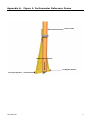
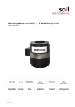
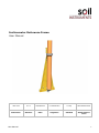
Inclinometer Reference Frame User Manual Man 155 2.0.1 06/08/2014 C. Rasmussen P. Day Chris Rasmussen Manual No. Revision Date Originator Checked Authorised for Issue User Manual 1 Contents Section 1 : Introduction ................................................................................................................................. 3 Section 2 : Mounting the Reference Frame ............................................................................................ 4 Section 3 : Checking Procedure .................................................................................................................. 5 3.01 3.02 Appendix A. User Manual For the ‘A’ Axis ............................................................................................................................... 5 For the ‘B’ Axis ............................................................................................................................... 5 Figure 1: Inclinometer Reference Frame ....................................................................... 6 2 Section 1 : Introduction The following procedure details the mounting of the Reference (checking) Frame and how to conduct a routine calibration check. The Reference Frame is primarily intended for checking that the inclinometer readings are repeatable over the lifetime of the equipment. This is carried out by periodically checking the inclinometer systems readings at zero, +10° and -10 to ensure they have not altered. The frame is to be mounted in the vertical position using the Inclinometer System which is to be eventually monitored. Consequently it is of paramount importance that the frame is mounted in a structurally sound position, which is not subjected to vibration, and is protected from physical disturbance. User Manual 3 Section 2 : Mounting the Reference Frame (Please refer to Appendix A. figure 1: Inclinometer Reference Frame) Suspend the apex of the frame on a vertical wall approximately 1m above ground level, using a single anchor bolt located immediately above the fulcrum point. Ensure the nut on the anchor bolt is only finger tight so that the frame can hang freely and via gravity find a near vertical position. Connect up the Inclinometer System and place the probe in the Reference Access Tube with the leading wheel (first wheel to enter the tube) pointing to your left and at 90 degrees to you. Switch the reel and then the PDA on and allow 15 minutes for the probe to stabilise. Ensure the reference tube is in the zero degree (middle) position. Rotate the frame about the upper anchor point until “zero” deflection is registered in direction “A” on the PDA, and carefully marks the positions for the two lower anchor bolt holes. Remove the probe from the Reference Access Tube, rotate the frame and drill and locate the remaining anchor bolts. Mount the frame in position ensuring all anchor bolt nuts are 1/4 turn over finger tight, sufficient to firmly hold the frame, but not to twist or distort it. Insert the probe as above, into the calibration tube, ensure that the frame is aligned correctly (zero 0.1mm is practical) and gently tighten the mounting nuts a further 1/2 to 1 turn. Remove probe, rotate 180° and reinsert, so that the leading wheel points to the right, this should confirm the zero reading. If not, remember that the average of the readings should be ± 0.1mm (i.e. +0.3 one direction and -0.4 on the other direction). If the average is within ± 0.1mm the frame is mounted vertically. The B axis should be within 0.5mm, if not shim between the frame and the wall until better than 0.5mm is achieved, then re-measure the A axis. Final adjustments are to be made accordingly without subjecting the frame and probe to mechanical shock and the frame fastened securely. Record readings achieved for future reference. User Manual 4 Section 3 : Checking Procedure 3.01 For the ‘A’ Axis Ensure probe and probe wheels are clean, and insert it into Reference Access Tube with the leading wheel facing to the left; note the zero reading (0.1mm). Rotate the Reference Access Tube to the +10 position. Rotate the Reference Access Tube to the -10 position. Remove the probe, rotate it through 180º and re-insert it into the calibration access tube with the leading wheel facing to the right. Rotate the Reference Access Tube to the +10º position. Rotate the Reference Access Tube to the -10º position. Calculate the average of the readings taken at the +10º position. It should be +86.8mm (± 0.1mm). Likewise at the -10º position the average should be -86.8mm (± 0.1mm). Note : If the Reference Frame is not absolutely vertical any plus/minus error will cancel out when adding the +10 and -10 average readings (ignoring the minus sign) and dividing by 2 to obtain the mean value. 3.02 For the ‘B’ Axis Repeat procedure above with the probe rotated 90º (facing forward) within the Reference Access Tube. Since this is the secondary axis, the reading repeatability may be reduced to ± 0.2mm. It is unlikely that the probe will drift over its lifetime, however if dropped or damaged, it is prudent to check that it is reading correctly. It should be emphasised that the integrity of the calibration check is dependent upon the frame remaining securely fixed in a stable position for the monitoring term. If you cannot obtain reliable data, or the average readings do not equal those expected, please contact Soil Instruments for assistance. Bell Lane, Uckfield, East Sussex t: +44 (0) 1825 765044 e: [email protected] TN22 1QL United Kingdom f: +44 (0) 1825 744398 w: www.itmsoil.com Soil Instruments Ltd. Registered in England. Number: 07960087. Registered Office: 5th Floor, 24 Old Bond Street, London, W1S 4AW User Manual 5 Appendix A. Figure 1: Inclinometer Reference Frame Access Tube Middle (Zero) position +10 Degree position -10 Degree position User Manual 6 INCLINOMETER CALIBRATION FRAME USER MANUAL 7 User Manual